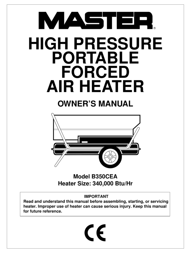
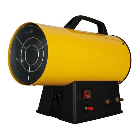
Desa B350D User manual

Technical Service Department • P.O. Box 90004 • 2701 Industrial Drive • Bowling Green, Kentucky 42102-9004
SERVICE MANUAL
HIGH PRESSURE
PORTABLE FORCED AIR HEATERS
600 SIDE PFA/PV 009
350 SIDE PFA/PV 008
INTERNATIONAL
DESA

HIGH PRESSURE PORTABLE FORCED AIR HEATER SERVICE MANUAL
2
TABLE
OF
CONTENTS
Section 1 - Safety Information.................................................................................3
Section 2 - Introduction
Arrangement of Manual......................................................................................4
Technical Service Department ...........................................................................4
Service Preparation............................................................................................4
Tools Required...................................................................................................4
Section 3 - General Specifications and Applications Information
Fuel Section .......................................................................................................5
Electrical.............................................................................................................5
Ventilation ..........................................................................................................5
Heater Sizing......................................................................................................5
Heater Performance Specifications....................................................................6
Wiring Diagrams.................................................................................................6
Section 4 - Component Operation
All Systems Working Together...........................................................................8
Fuel System .......................................................................................................8
Fuel Pump......................................................................................................8
Fuel Filters .....................................................................................................9
Nozzle ............................................................................................................9
Electrical System................................................................................................10
Motor ..............................................................................................................10
Flame Control Assembly ................................................................................10
Ignition Transformer .......................................................................................11
Fuel Solenoid Valve .......................................................................................11
Fan Switch .....................................................................................................11
Section 5 - Troubleshooting
Safety Requirements .........................................................................................12
Using an Ohmmeter...........................................................................................12
Setting Up the Ohmmeter ..................................................................................12
Calibrating the Ohmmeter..................................................................................12
Diagnostic Information .......................................................................................12
Problem Conditions
Frequent Spark Plug Fouling/Delayed Ignition ..............................................13
Spark Plug Sparks, but Motor Does Not Start ...............................................14
Motor Starts, but Heater Will Not Ignite .........................................................15
Heater Ignites, and Flame Is Established, However, Flame Control Trips,
and Heater Shuts Off .................................................................................18
Heater Does Not Start. Motor and Transformer Do Not Operate...................21
Carbon Build-Up Inside Combustion Chamber..............................................22
Section 6 - Accessories and Service Information....................................................23

HIGH PRESSURE PORTABLE FORCED AIR HEATER SERVICE MANUAL
3
SAFETY INFORMATION
Safety Requirements
Thisservicemanualisintendedforusebyindividualswithadequateelectricalandmechanical
skills. Attempts to repair this heater by individuals without those skills can result in personal
injury as well as property damage.
1
SECTION
IMPORTANT:
ReadtheOwner’sManual carefully andcompletelybeforetryingto assemble,
operate, or service this heater. Improper use of this heater can cause serious injury or death
from burns, fire, explosion, electrical shock, and carbon monoxide poisoning.
Make certain you read and understand all Warnings.
Warnings
!
WARNING ICON G 001
• Use only kerosene or No. 1 fuel oil to avoid risk of fire or explosion. Never use gasoline,
naphtha, paint thinners, alcohol, or other highly flammable fuels.
• Never use heater where gasoline, paint thinner, or other highly flammable vapors are
present.
• Follow all local ordinances and codes when using heater.
• Use only in well vented areas. Provide at least three (3) square feet of fresh, outside air for
each 100,000 BTU/Hr of rating. This heater produces carbon monoxide, which is listed by
the State of California as a reproductive toxin under Proposition 65.
• Use only in places free of flammable vapors or high dust content.
• Use only with the electrical voltage and frequency specified on model plate.
• Use only a three-prong, grounded extension cord.
• Minimum heater clearances from combustibles:
Outlet: 8 Ft. Sides: 4 Ft. Top: 4 Ft. Rear: 4 Ft.
• Locate heater on a stable and level surface while hot or running or a fire may occur.
• When moving or storing, heater must be in a level position or fuel spillage may occur.
• Keep children and animals away from heater.
• Unplug heater when not in use.
• This heater is equipped with a thermostat. When plugged in, heater may start anytime.
• Never use heater in living or sleeping areas.
• Never block air inlet (rear) or air outlet (front) of heater.
• Never move, handle, refuel, or service a hot, operating, or plugged in heater.
• Never attach duct work to front or rear of heater.

HIGH PRESSURE PORTABLE FORCED AIR HEATER SERVICE MANUAL
4
2
SECTION
Pressure Gage
INTRODUCTION
Arrangement Of Manual
This manual contains information and serv-
ice procedures that help the service person
understand and correct problems on the
DESA International High Pressure Portable
ForcedAirHeater.Thefirstpartofthismanual
contains basic information about the opera-
tion of different parts of the heater. Review
this information. It provides a basic under-
standing of how the parts function in the
working system. The last part of this manual
is a troubleshooting section. It provides a
quickreferenceconcerningconditionswhich
may result in customer complaints. These
procedures will help the service person
quickly diagnose a malfunctioning heater.
The illustrations in this manual may not nec-
essarilydepicttheactualheatermodel.They
are intended for reference only.
Technical Service Department
The Technical Service Department, located
inBowlingGreen,Kentucky,is committed to
helpincreasetheserviceknowledgeofthose
who service these heaters. This will enable
service people to provide prompt, efficient
service.Thisservicemanualcoversthemajor
problems that can occur with the heaters.
However, as with any product, certain prob-
lems can arise which this manual does not
cover.Ifsuchproblemsarise,pleasecallthe
TechnicalServiceDepartmentat1-800-323-
5190. The Technical Service Department is
openfrom8:00amto4:00pmCentralTime.
This number is only for servicing problems
andcannotbeusedfororderingparts,billing
questions, etc.
Service Preparation
A clean work area at the start of each job is
essential for efficient service work. Clean
extremely dirty heaters before servicing.
Cleaning will sometimes uncover the prob-
lem area. Gather tools needed for the job
beforeworkisstarted.Havingtolocatetools
causes delays that lead to lost time and
wages.
Always use clean fuel when testing heater.
Many problems are often caused by the
wrong type of fuel or dirty fuel.
Usecautionandcommonsensewhenwork-
ing on heater. Always remember:
• Kerosene is combustible.
• Guard against electrical shock.
• Heater parts get hot during operation.
Touching these parts can cause severe
burns.
Tools Required
In addition to common hand tools, the serv-
iceshopshouldhavethefollowingtoolsand
instruments to properly repair the heater.
These tools and instruments will be referred
to throughout this manual.
Tool/ Part
Instrument Range Number
Volt Ohmmeter RX1/AC 250V *
Feeler Gage .001 to .1 inch **
Pressure Gage 0-200 PSI M4574
Flame Control/
Photocell Tester HA1170
* Available at most electronic stores.
** Available at any auto parts store.
CAUTION: OBSERVE SAFETY RULES
V- MA
0
1000300
100
30
10
3
1000
300
100
30
10
3
1
.1
10
1000
100
x1
x10
x100
x1K
x10K
D
C
V
D
M
C
A
COM-
A
C
V
T
E
S
T
5
10
15
20
25
30
1
2
3
4
5
8
6
9
10
7
OFF
Volt Ohmmeter
.025
.0015
Feeler Gage

HIGH PRESSURE PORTABLE FORCED AIR HEATER SERVICE MANUAL
5
Fuel Selection
One of the most critical specifications for
trouble-free operation is the use of a clean,
acceptable fuel. Listed below are guidelines
andcommentsconcerningoperationofheat-
ers with different fuels.
Recommended
Fuels Comments
Kerosene Best overall results. Mini-
Fuel Oil No. 1 mum odor and minimum
Jet “A” maintenance.Noadditives
necessaryforcoldweather
operation.
Alternate Fuels Comments
Fuel Oil No. 2 Noticeable increase in
Diesel No. 1 odor. Requires frequent
Diesel No. 2 maintenance of fuel filter,
nozzle and spark plug.
Cannot be used at tem-
peratures below +20°F.
Electrical
Connectheatertoastandardelectricaloutlet
(120V/60Hz) to operate. For safety, all heat-
ers have a three-prong, grounded power
cord. Plug power cord of heater into three-
prong, grounded extension cord. Extension
cordmustbeatleastsixfeetlong.Makesure
youuseextensioncordlargeenoughtocarry
the voltage the heater requires. Use the
following chart to determine the proper size
extension cord for heater.
Length of Cord Wire Size (AWG)
100 ft. No. 14
200 ft. No. 12
300 ft. No. 10
400 ft. No. 8
500 ft. No. 6
3
SECTION
Ventilation
Onlyuseheaterinwell-ventilatedareas.The
following chart shows the minimum fresh,
outside air opening needed for proper venti-
lation.
Heater Size Square Foot
(BTU/Hr) Opening
250,000 7.5
300,000 9.0
350,000 10.5
600,000 18.0
The above chart is based on ventilation re-
quirementsofatleasta three (3)squarefoot
fresh, outside air opening for each 100,000
BTU/Hr of rating. Provide extra fresh air if
usingmoreheaters.Ifpossible,providecross-
ventilation for better air movement. This
heater produces carbon monoxide, which is
listed by the State of California as a repro-
ductive toxin under Proposition 65.
Heater Sizing
Use heater which is properly sized for the
area to be heated. Listed below is a simple
formula that allows you to determine heater
BTU/Hr size requirements.
Cubic Feet of Area x .133 x Desired
Temperature Rise °F = BTU size
Example
Area: 100' x 100' x 8' = 80,000 Cubic Feet
Desired Temperature Rise: 30°F
80,000 (Cubic Feet)
x .133 (Factor)
10,640
x 30 (Temperature Rise)
319,200 (BTUs/Hr Needed)
Answer: Use a 350,000 BTU/Hr
heater for this heating example.
GENERAL SPECIFICATIONS AND APPLICATIONS INFORMATION

HIGH PRESSURE PORTABLE FORCED AIR HEATER SERVICE MANUAL
6
Heater Performance Specifications
350,000 BTU/Hr 600,000 BTU/Hr
Output Rating (BTU/Hr) 350,000 600,000
Fuel Use only kerosene or No. 1 fuel oil
Fuel Tank Capacity (U.S. Gallons) 30 36
Fuel Consumption (Gallons Per Hour) 2.5 4
Electric Requirements 120V/60Hz 120V/60Hz
Amperage (Normal Run) 7.1 11.5
Motor RPM 1725 1725
Fuel Pump Pressure (PSI) 100 110
Spark Plug Gap .050/.060" .050/.060"
Weight (Approx. Lbs.)
Dry 180 285
With Full Fuel Tank 390 550
Wiring Diagrams
Wiring Diagram for Non-Terminal Block Heater with Standard Flame Control
1
2
3
RELAY
AB
75
FLAME
CONTROL
WHITE
ORANGE
RED
GREEN
MOTOR
PHOTO-
CELL
BLUE
BLACK
SPARK PLUG
BLACK
BLACK
BLACK
BLACK
BLACK
WHITE
WHITE
WHITE
WHITE
WHITE
RED
RED
RED
WHITE
BLUE
FAN
SWITCH
T
R
A
N
S
F
O
R
M
E
R
ORANGE
YELLOW YELLOW
THERMOSTAT
SOLENOID
VALVE
R
B
WHITE

HIGH PRESSURE PORTABLE FORCED AIR HEATER SERVICE MANUAL
7
Wiring Diagram for Terminal Block Heater with Standard Flame Control
Wiring Diagram for Non-Terminal Block Heater with White-Rogers/Robert Shaw Flame Control
FAN
SWITCH
SPARK PLUG
ORANGE
BLACK
FLAME
CONTROL
WHITE
THERMOSTAT
WHITE
WHITEBLUE
PHOTO
CELL WHITE
GREEN
BLACK
BLACK
WHITE
ORANGE
ORANGE
RED
RED
RED
YELLOWYELLOW
SOLENOID
VALVE WHITE
MOTOR
T
R
A
N
S
F
O
R
M
E
R
32
1
WHITE
WHITE
BLACK
WHITE WHITE
1
3
2
FAN
SWITCH
75
BA
MOTOR
RELAY
WHITE
RED ORANGE
ORANGE
RED
BLACK
WHITE
BLACK
WHITE
BLUE
BLUEWHITE
BLACK BLACK
THERMOSTAT B
R
FLAME
CONTROL RESET
BUTTON
RED
YELLOW
YELLOW RED
WHITE
SOLENOID
VALVE
WHITE
TERMINAL
BOARD
TERMINAL
BOARD
TRANSFORMER
WHITE
SPARK
PLUG
PHOTOCELL
BLACK
WHITE
GREEN
YELLOW
WHITE

HIGH PRESSURE PORTABLE FORCED AIR HEATER SERVICE MANUAL
8
COMPONENT OPERATION
All Systems Working Together
There are four basic systems within the
heater: the fuel system, the air system, the
ignition system, and the flame control sys-
tem.
The Fuel System: The fuel pump pulls fuel
fromthefueltankandpressurizesit.Thefuel
pump pushes fuel through a filter and a
solenoid valve and out the burner head
nozzle. A fine mist of fuel is sprayed into the
combustion chamber.
The Air System: The motor turns the fan.
The fan pushes air into and around the
4
SECTION
FUEL SYSTEM
Fuel Pump
The fuel pump is a single stage gear-type
pumpdesignedfortwo-pipeusage.Theterm
“two-pipeusage”meansthatprovisionsmust
bemadetoreturnexcessfuelfromthepump
backtosupplytank.Figure1showsposition
of pump on heater.
Thefuelpumpisdirectly connected tomotor
shaft. When motor on heater runs, the fuel
pump starts working. The fuel pump draws
fuel into one of the ports marked “INLETS.”
After fuel pump draws fuel into INLET port,
thefuelisthenpressurizedin the pump. The
fuelpumpthenforcesfueltotheburnerhead
nozzle thru the port marked NOZZLE.
The port marked “PRESS ADJ” contains an
adjustment screw. Turning this screw will
increase or decrease the fuel pump pres-
sure.Checkfuelpumppressurebyattaching
high pressure gauge into the port marked
“GAGE.”
As mentioned above, the port marked “RE-
TURN” is used to return excess fuel back to
supply tank.
Be careful when working on fuel pump. Fuel
pump operates under high pressure.
Figure 1 - Fuel Pump
PUMP
MODEL PRESSURE
350,000 BTU/Hr. 100 psi
600,000 BTU/Hr. 110 psi
combustion chamber. The air that goes into
the combustion chamber mixes with the fuel
for combustion. The air is heated and pro-
vides a stream of clean, hot air.
TheIgnitionSystem:Thetransformersends
voltage to the spark plug. The spark plug
ignites the fuel and air mixture.
The Flame Control System: This system
causes the heater to shut down if the flame
goes out. It also allows the fan to continue
running after normal shutdown of heater.
This cools the combustion chamber.

HIGH PRESSURE PORTABLE FORCED AIR HEATER SERVICE MANUAL
9
Fuel Filters
The fuel filtering system has two filters. The
first filter is a 50-mesh screen type. It is
located in the fuel tank below the grommet
where fuel suction and return lines enter the
tank. The filter is connected to both the fuel
input (suction side) and the return line from
thefuelpump.Thisuniquedesignallowsthe
filter to backflush or clean itself of sediment
by the action of the excess flow returning
from the pump.
The second filter is a canister type. The two-
piece canister contains a replaceable drop-in
filterelement.Thisfilterwillfilteroutverysmall
particles which may be present in the fuel
system.Thishighdegreeoffilteringisneeded
to prevent any sediment or foreign material
from reaching the nozzle. Make sure to clean
orreplacethisfilterelementevery250hoursof
operation. Clean or replace this filter more
often if fuel quality is bad.
Nozzle
The nozzle could be classified as the heart of
the fuel system. The nozzle works similar to a
standard garden hose nozzle. The kerosene
passes through the nozzle. Under pressure,
the oil expands through the nozzle orifice and
breaksintoa fine spray. The flow rate and the
spray angle is designed into each nozzle. Do
not substitute with a nozzle having a different
flow rate or spray pattern. Use only replace-
ment parts supplied by DESA International.
Figure 3 - Canister Type Fuel Filter
Figure 2 - Fuel Filter in Fuel Tank
Filter
Figure 4 - Nozzle

HIGH PRESSURE PORTABLE FORCED AIR HEATER SERVICE MANUAL
10
Flame Control Assembly
Theheaterisequippedwithoneoftwoflame
controls — a White-Rogers/Robert Shaw or
a standard flame control. The flame control
monitors the combustion chamber flame.
The control will shut off power to the heater
if the combustion flame goes out or if an
inside the motor. The centrifugal switch also
supplies voltage to the fuel solenoid valve.
The motor also has a temperature/current
sensitive thermal protector wired in series
with both windings. This device protects the
motorfromoverheatingifthefan/pumplocks
up. If the fan/pump locks up, this device will
shut the motor off. Before motor will run
again, press red reset button located on top
of the motor housing (see Figure 5).
Figure 6 - White-Rogers/Robert Shaw
Flame Control Figure 7 - Standard Flame Control
RESET
ELECTRICAL SYSTEM
Motor
The motor is a fractional horsepower motor.
The motor drives the fuel pump and rotates
the fan. The turning fan delivers air into and
around the combustion chamber.
The motor contains two separate internal
windings. The first winding is the start wind-
ing.Thesecondwindingisthemainwinding.
The motor switches power from the start
winding to the main winding after the motor
reaches75%ofitsratedspeed.Thisswitch-
ing is done by a centrifugal switch located
unusual flame color is present. A photocell
(attached to the burner head) monitors light
within the chamber. If the photocell detects
improper combustion or loss of flame, the
flamecontrolwillshutoffpowertotheheater.
Reset Button
Figure 5 - Motor

HIGH PRESSURE PORTABLE FORCED AIR HEATER SERVICE MANUAL
11
Figure 10 - Fan Switch
Fan Switch
The fan switch is a two-position, tempera-
ture-activated, bi-metal switch. The switch
allowsthemotortocontinueturningfanafter
thermostat shuts off heater. This helps cool
the combustion chamber.
When the heater is first turned on, power to
the motor is routed thru the thermostat,
flame control, and the normally closed con-
tactsoneand three of the fan switch. After a
fewminutesofoperation,thetemperatureof
the combustion chamber increases. This
causes the bi-metal material within the fan
switch to warp and close contacts one and
twoandopencontactsoneandthree.Power
tothemotor isthenroutedthrucontactsone
Fuel Solenoid Valve
The solenoid valve is an electro-magnetic
device. It is mounted directly behind the
burner head body. The solenoid valve acts
as an on/off valve for fuel flow to the nozzle.
When the thermostat on the heater turns
heater on, the solenoid valve opens, allow-
ing fuel to flow to the nozzle. When the
thermostatontheheaterturnsheateroff,the
solenoid valve closes, preventing fuel from
reaching the nozzle.
Figure 9 - Fuel Solenoid Valve
Figure 8 - Ignition Transformer
Ignition Transformer
The ignition transformer operates on 120V/
60Hz.Itdeliversapproximately5,000voltsto
thesparkplug.Thesparkplugignitesthefuel
sprayedfromthenozzleassembly.The igni-
tiontransformeroperatescontinuouslywhile
the heater is running.
The ignition transformer has no internal ser-
viceparts.Replacetheignitiontransformerif
defective.
andtwo,bypassingtheflamecontrolandthe
thermostat. This switch allows the motor
and fan to continue to run. When the cham-
ber cools enough to allow the fan switch to
close contacts one and three, the motor will
shut off.
!
WARNINGICON G001
WARNING
Transformer has high voltage output.
Alwaysunplugheater before replacing
transformer.Useextremecautionwhen
testing transformer. Severe electrical
shock can occur.

HIGH PRESSURE PORTABLE FORCED AIR HEATER SERVICE MANUAL
12
5
SECTIONTROUBLESHOOTING
Safety Requirements
!
WARNINGICON G001
WARNING
This service manual is intended for
use by persons with adequate electri-
calandmechanicalskills.Onlyattempt
torepairheaterifyouhavetheseskills.
Personal injury and property damage
can occur to those who attempt to
repair heater without these skills.
!
WARNINGICON G001
WARNING
• Unplug heater and let cool before
servicing. Note: Certain test require
you to connect heater to electrical
outlet. If so, only connect heater for
time needed to complete test.
• Do not bypass any safety devices.
!
WARNINGICON G001
CAUTION
• Ifreplacementpartsareneeded,only
use factory authorized replacement
parts. Do not substitute with non-
factory parts.
• Makesureallelectricalconnections
aresecureand allharnessleads are
inplacebeforeconnectingheaterto
electrical outlet.
Using an Ohmmeter
Throughout the diagnostic procedures, we
require you to check continuity of the electri-
calcircuits.Youwilldothisusinganohmme-
ter. To set up the ohmmeter for these test,
follow the instructions below.
Setting Up the Ohmmeter
1. There is a small plastic screw in the
center of the ohmmeter, just under the
meter needle. Turning this screw will
move the needle. Turn the screw to ad-
justthemeterneedletothezero“0”mark
onthefarleftofthescale(seeFigure11).
2. Make sure batteries are in ohmmeter.
Set ohmmeter on the RX1 position.
3. Plug test leads into ohmmeter. If test
leads do not have alligator clips, install
alligator clips to leads.
CAUTION: OBSERVE SAFETY RULES
V- MA
0
1000300
100
30
10
3
1000
300
100
30
10
3
1
.1
10
1000
100
x1
x10
x100
x1K
x10K
D
C
V
D
M
C
A
COM-
A
C
V
T
E
S
T
5
10
15
20
25
30
1
2
3
4
5
8
6
9
10
7
OFF
Figure 11 - Ohmmeter Adjusted to “O” Mark
Calibrating the Ohmmeter
1. Connect the alligator clips to each other
(see Figure 12). The meter needle should
movetothefarrightoftheohmsscale(Ω).
2. Use the OHM thumb adjustment knob to
adjust the meter needle to the zero “0”
markonthefarrightoftheohmscale(Ω).
Note:
If you are using a digital ohmmeter,
calibrateaccordingtomanufacturer’sinstruc-
tions.
Diagnostic Information
The following pages contain various diag-
nostic information. To use the information,
determinewhatproblemconditionsexistand
followthetestprocedureslistedforthatprob-
lem.
CAUTION: OBSERVE SAFETY RULES
V- MA
0
1000300
100
30
10
3
1000
300
100
30
10
3
1
.1
10
1000
100
x1
x10
x100
x1K
x10K
D
C
V
D
M
C
A
COM-
A
C
V
T
E
S
T
5
10
15
20
25
30
1
2
3
4
5
8
6
9
10
7
OFF
Figure 12 - Ohmmeter with
Alligator Clips Connected

HIGH PRESSURE PORTABLE FORCED AIR HEATER SERVICE MANUAL
13
C. Incorrect fuel pump pressure
1. Install pressure gage to fuel pump port
marked “GAGE.” This gage should have
a full scale reading of 150-200 psi.
2. Connectheatertoelectricalpowertotest
fire heater.
3. Adjust pump pressure by turning slotted
screwatfuelpump port marked“PRESS
ADJ.” Turn screw clockwise to increase
pressure. Turn screw counterclockwise
todecreasepressure.SeeHEATERPER-
FORMANCESPECIFICATIONSonpage
6 for proper fuel pump pressure.
D. Dirty or damaged nozzle
1. Remove upper shell of heater.
2. Remove burner head from combustion
chamber.
3. Remove nozzle from burner head.
4. If nozzle is dirty, do not attempt to clean
by inserting wire into orifice opening.
Soak nozzle in a non-flammable solvent
and use compressed air to dislodge any
dirt in nozzle. Replace worn or damaged
nozzle with new nozzle.
POSSIBLE CAUSES
A. Poor fuel quality
B. Sparkplugtipistooclosetospraypattern
of nozzle
C. Incorrect fuel pump pressure
D. Dirty or damaged nozzle
TEST PROCEDURES
A. Poor fuel quality
Usegoodqualityfuel.SeeGENERALSPECI-
FICATIONS AND APPLICATIONS INFOR-
MATION, page 5, for fuel guidelines.
B. Spark plug tip is too close to spray
pattern of nozzle
1. Remove upper shell of heater.
2. Remove spark plug from burner head.
3. Cleanandregapsparkplug.Correct gap
for spark plug is .05/.06 inch.
4. Install plug in burner head.
5. Replace upper shell on heater.
6. Connectheatertoelectricalsupplytotest
fire heater.
7. Shut heater off, unplug heater, and re-
movesparkplugtodetermineifelectrode
is wet. If electrode is wet, place a 0.1"
metal washer/spacer between burner
head and spark plug. This will keep the
plug out of the spray pattern of nozzle.
8. Retest heater. Install additional metal
washer(s)/spacer(s) if needed.
psi
Figure 14 - Checking Fuel Pump Pressure
1/4 NPT
(Pipe) Threads
Figure 13 - Adding Metal
Washer/Spacer to Spark Plug
Figure 15 - Nozzle
TROUBLESHOOTING — PROBLEM CONDITIONS
OBSERVED PROBLEM
Frequent spark plug fouling/delayed ignition

HIGH PRESSURE PORTABLE FORCED AIR HEATER SERVICE MANUAL
14
TROUBLESHOOTING — PROBLEM CONDITIONS
OBSERVED PROBLEM
Spark plug sparks, but motor does not start.
POSSIBLE CAUSE
A. Motor protector tripped
B. Fuel pump seized
C. Defective motor
D. Defective relay (if equipped)
E. Defective fan switch
TEST PROCEDURES
A. Motor protector tripped
Depress red motor protector reset button on
top of motor case. This resets the motor
protector for proper operation. Determine
causes for motor protector trips before re-
turning heater to customer.
B. Fuel pump seized
1. Unplug heater.
2. Remove upper shell of heater.
3. Rotate fan by hand to determine if pump
is free to turn.
4. If fan is difficult or impossible to rotate,
loosen clamp which holds fuel pump to
motor. Rotate fan and retighten clamp.
5. If fan is still difficult or impossible to
rotate, replace fuel pump.
C. Defective motor
1. Depress red motor protector reset but-
ton on top of motor case before testing
motor.
2. Unplug heater.
3. Disconnecttheredandwhitemotorwires
at their wire connection.
4. Set ohmmeter on the RX1 position.
5. Connect ohmmeter test leads to red and
white motor wire. If the resistance indi-
catedreads0ohmsorindicates an open
circuit,themotorisdefectiveandmustbe
replaced.
Note:
Proper resistance for
motor is 1.0 to 1.5 ohms. Make sure you
properly calibrate ohmmeter before test-
ing motor.
D. Defective relay (if equipped)
Replace defective relay.
E. Defective fan switch
Follow steps under DEFECTIVE FAN
SWITCH, procedure “D” on page 20.
Figure 17 - Rotating Fan by Hand
Reset Button
Figure 16 - Reset Button Location
Figure 18 - Testing Motor with Ohmmeter

HIGH PRESSURE PORTABLE FORCED AIR HEATER SERVICE MANUAL
15
TROUBLESHOOTING — PROBLEM CONDITIONS
OBSERVED PROBLEM
Motor starts, but heater will not ignite.
POSSIBLE CAUSE
If No Spark Observed at Spark Plug
A. Spark plug has incorrect gap
B. Defective transformer or transformer not
grounded properly
C. Cracked spark plug
POSSIBLE CAUSE
If Spark Observed at Spark Plug
D. Incorrect fuel pump pressure
E. Defective fuel solenoid valve
F. Fuel line leak on suction side of pump
G. Dirty or damaged nozzle
H. Dirty fuel filter
TEST PROCEDURES
A. Spark plug has incorrect gap
1. Unplug heater.
2. Remove upper shell of heater.
3. Remove spark plug from burner head.
4. Checkgapbetweensparkplugelectrodes
with feeler gage. Correct gap for spark
plug is .05/.06 inch. Reset gap if needed.
5. Follow steps in procedure “B” to test for
spark at spark plug electrodes.
Figure 19 - Proper Gap between
Spark Plug Electrodes
.05/.06 inch
1. Unplug heater.
2. Remove upper shell of heater.
3. Remove spark plug from burner head.
Makesuresparkplugisproperlygapped
(see test procedure “A” for spark plug
gap)
4. Check to make sure the transformer is
properly grounded by the 2 mounting
screws. Look for loose fasteners, corro-
sion, broken tabs, etc.
5. Connectthetransformersecondarylead
to the spark plug.
6. Establish a good ground between the
spark plug body and heater. To do this,
attach a grounding wire to heater shell.
Clip grounding wire to grounding (outer)
electrode on spark plug (see Figure 20).
Useinsulated pliers to hold spark plug at
spark plug hex (see Figure 20).
Note:
Only use pliers with plastic or rubber-
sleeved handles.
7. Connect heater to electrical supply.
8. Lookforsparkbetweenelectrodes. Ifthe
ground is good and there is no spark
between electrodes, the transformer is
defective.
Note:
No spark between elec-
trodesmaybecausedby crackedporce-
lain on the spark plug. Before replacing
transformer, see test procedure “C” on
page 16. If porcelain on spark plug is not
cracked, proceed with replacing defec-
tive transformer.
Figure 20 - Grounding Spark Plug
B. Defective transformer
Grounding
Wire
!
WARNINGICON G001
WARNING
Before attempting this test procedure,
remove fan from motor and disconnect
electricalleadsfromfuelsolenoidvalve.
Thiswillpreventinjury from turningfan
or accidental ignition of fuel.
!
WARNINGICON G001
WARNING
After connecting heater to electrical
supply, do not touch spark plug elec-
trodes.Sparkplugproduceshighvolt-
age. Electrical shock will occur.
Continued

HIGH PRESSURE PORTABLE FORCED AIR HEATER SERVICE MANUAL
16
C. Cracked spark plug
Follow steps under DEFECTIVE TRANS-
FORMER, procedure “B” on page 15, to test
for spark at spark plug electrodes. If spark is
seen at any place on the spark plug other
thantheelectrodes,theporcelaininsulatoris
cracked. Replace spark plug.
D. Incorrect fuel pump pressure
FollowstepsunderINCORRECTFUELPUMP
PRESSURE, procedure “C” on page 13.
E. Defective fuel solenoid valve
1. Remove upper shell of heater.
2. Check for fuel flow to nozzle. Do this by
turningthermostatknobtowarmestposi-
tion and connecting heater to electrical
supply.Withmotor running,lookthrough
airopeningsonrearofcombustioncham-
ber. See if nozzle is spraying out fuel. If
nozzleissprayingoutfuel,solenoidvalve
isworkingproperly.Ifnozzleisnotspray-
ing out fuel, unplug heater and follow
stepsbelowtodetermineifsolenoidvalve
is defective.
3. Disconnect yellow and white wires from
solenoid valve.
4. Set ohmmeter on the 250VAC position.
5. Connect ohmmeter test leads to yellow
and white wires that were connected to
solenoid valve.
6. Connect heater to electrical supply. If
120VAC is being sent to solenoid valve
and fuel pump pressure is correct, the
solenoid valve is defective. Replace de-
fective solenoid valve.
Figure 21 - Checking Fuel Solenoid Valve
!
WARNINGICON G001
WARNING
Beforeattemptingthistestprocedure,
removefanfrommotorandsparkplug
wirefromspark plug. Thiswillprevent
injury from turning fan or accidental
ignition of fuel.
!
WARNINGICON G001
WARNING
Do not touch metal end of spark plug
wirewhileheaterisrunning.Makesure
metal end of spark plug wire does not
touch any part of heater. Spark plug
wire produces high voltage. Electrical
shock will occur.

HIGH PRESSURE PORTABLE FORCED AIR HEATER SERVICE MANUAL
17
F.Fuel line leak on suction side of
pump
Checkallfuellinesonthe suction side of the
pumpfortightness.Anairleakinoneofthese
fittingscanallowairtoenterthesystem.This
will result in improper pump pressure.
G. Dirty or damaged nozzle
Follow steps under DIRTY OR DAMAGED
NOZZLE, procedure “D” on page 13.
Figure 23 - Removing Fuel Filter
H. Dirty fuel filter
The fuel filter at fuel pump is housed in the
fuel filter canister.
1. Remove canister bottom from canister
top.
2. Remove fuel filter from canister bottom.
3. Inspect canister bottom and fuel filter for
water or accumulated dirt.
4. Rinsecanisterbottomincleankerosene.
5. Wipe dry with a clean cloth.
6. Iffuelfilterisdirtyandmadeofwiremesh,
clean it thoroughly in clean kerosene.
7. If fuel filter is dirty and made of fiber,
replace with new fuel filter and gasket.
Figure 22 - Fuel Line Check Points

HIGH PRESSURE PORTABLE FORCED AIR HEATER SERVICE MANUAL
18
TROUBLESHOOTING — PROBLEM CONDITIONS
OBSERVED PROBLEM
Heater ignites, and flame is established, however, flame control trips, and
heater shuts off.
POSSIBLE CAUSE
If Flame Control Trips Out within
First Minute of Operation
A. Defective flame control
B. Defective or dirty photocell
C. Loose wire nut connection
POSSIBLE CAUSE
If Flame Control Trips Out after
Several Minutes of Operation
D. Defective fan switch
E. Incorrect fuel pump pressure
F. Restricted fuel filter
G. Dirty photocell
TEST PROCEDURES
A. Defective flame control
Theheaterisequippedwithoneoftwoflame
controls.
1. White-Rogers/Robert Shaw flame control
2. Standard flame control
The White-Rogers/Robert Shaw flame con-
trolislargeandsquare.Itismountedbeside
themotoronthewiringcoverplate.Itiseither
black or grey in color with the reset button
locatedontop.Thestandardflamecontrolis
muchsmallerthantheWhite-Rogers/Robert
Shaw flame control. It is located beside the
motorandcoveredbythewiringcoverplate.
Theresetbuttonislocatedon the side of the
motor support.
Follow the directions below that match the
flame control on your heater.
White-Rogers/Robert Shaw Flame Control
Part Number M50230
1. Unplug heater.
2. Remove upper shell of heater.
3. Disconnect the two photocell wires from
the terminals marked F-F on flame con-
trol.
4. Makeajumperwire.Connectjumperwire
to terminals marked F-F on flame control.
5. Depress reset button on flame control.
6. Removeoneendofjumperwirefromone
of the F-F terminals.
7. Replace upper shell on heater.
8. Connect heater to electrical supply.
9. When motor starts, securely reconnect
jumper wire to F-F terminal.
IMPORTANT:
Make this connection
within 10 seconds after motor starts.
10.If reset button on flame control pops out
and heater shuts off, the flame control is
defective and must be replaced.
11.If heater continues to run for 5 minutes
and reset button does not pop out, the
problem is not in the flame control.
RESET
FF
Figure 24 - Flame Control with Jumper Wire
Connected to F-F Terminal
RESET
FF
Figure 25 - Flame Control with One End of
Jumper Wire Removed from F-F Terminal

HIGH PRESSURE PORTABLE FORCED AIR HEATER SERVICE MANUAL
19
Standard Flame Control
Part Number M50671-01
1. Unplug heater.
2. Remove upper shell of heater.
3. Check flame control with HA1170 tester
or use the following procedure.
A. Disconnect blue and white flame con-
trol wires from blue and white photo-
cell wires. These wires are connected
by small wire nuts near photocell.
B. Connect blue flame control wire to
white flame control wire. Use wire nut
to make connection. Make sure wires
are clear of fan.
C.Replace upper shell on heater.
D.Connect heater to electrical supply.
E. If reset button on flame control pops
out and heater shuts off, the flame
control is defective and must be re-
placed. If heater continues to run and
reset button does not pop out, the
problem is not in the flame control.
B. Defective or dirty photocell
1. Unplug heater.
2. Remove upper shell of heater.
3. Removephotocellfromphotocellbracket
attached to burner head.
4. If lens is dirty, wipe off with clean, soft
cloth.
5. Replace photocell.
6. Replace upper shell on heater.
7. Connectheatertoelectricalsupply.Ifprob-
lem remains, continue with steps below.
8. Unplug heater.
9. Remove upper shell of heater.
10.Removephotocellfromphotocellbracket
attached to burner head.
11.Check photocell with HA1170 tester or
use the following procedure.
A. Disconnect blue and white photocell
wires from blue and white flame con-
trol wires. These wires are connected
by small wire nuts near photocell.
B. Set ohmmeter on the RX1K position.
C.Connect the ohmmeter test leads to
the photocell wires.
D.Holdphotocelllensuptoalightsource
(60 watt light bulb or direct sunlight).
Make sure lens is facing light source.
The resistance indicated on the ohm-
meter should be less than 500 ohms.
E. Block off light source completely by
holdingtheopeningofphotocellagainst
a smooth, flat surface such as the fuel
tank.Within10secondstheresistance
indicated on the ohmmeter should be
greater than 250,000 ohms.
F. Replace photocell if any of these con-
ditions are not met during testing.
C. Loose wire nut connection
Check all electrical connections for tightness.
Figure 26 - Cleaning Lens of Photocell
Continued

HIGH PRESSURE PORTABLE FORCED AIR HEATER SERVICE MANUAL
20
D. Defective fan switch
1. Unplug heater.
2. Remove upper shell of heater.
3. Remove fan switch from heater.
4. Set ohmmeter to RX1K scale.
5. Connect test leads from ohmmeter to
terminals marked 1 and 3 on fan switch.
Theohmmetershouldmoveupscaleand
read continuity (0 ohms).
Note:
Make
sure fan switch is at room temperature
before performing this test.
3
2
1
Figure 27 - Fan Switch
Figure 28 - Testing Terminals 1 and 3
of Fan Switch
6. Connect test leads from ohmmeter to
terminals marked 1 and 2 on fan switch.
7. Applyalowlevelofheattothefaceofthe
switch. Do this with a lit match, heated
soldering iron, etc. Ohmmeter should
readcontinuity(0ohms)whenfanswitch
is heated.
8. Replace fan switch if any of these condi-
tions are not met during testing.
E. Incorrect fuel pump pressure
FollowstepsunderINCORRECTFUELPUMP
PRESSURE, procedure “C” on page 13.
F. Dirty fuel filter
Follow steps under DIRTY FUEL FILTER,
procedure “H” on page 17.
G. Dirty photocell
Followsteps1thru5underDEFECTIVEOR
DIRTYPHOTOCELL,procedure“B”onpage
19.
Figure 29 - Testing Terminals 1 and 2
of Fan Switch
Other manuals for B350D
1
Table of contents
Other Desa Heater manuals
Popular Heater manuals by other brands

Opranic
Opranic Thor user manual

Webasto
Webasto DBW 2020 Service and repair manual

EOS
EOS Finnrock 94.5664 Installation and operation manual

Dru
Dru Metro 80E Installation and service manual

Ridea
Ridea Living Othello Mono Slim Instruction and installation booklet

Hortus
Hortus Golden Tube 211-390 instructions