EnglishEnglish
32
WARNING:
Read all safety warnings,
instructions, illustrations and specications
provided with this product. Failure to follow all
instructions listed below may result in serious injury.
3) WORK AREA SAFETY
2) GENERAL REQUIREMENT
1) PERSONAL SAFETY
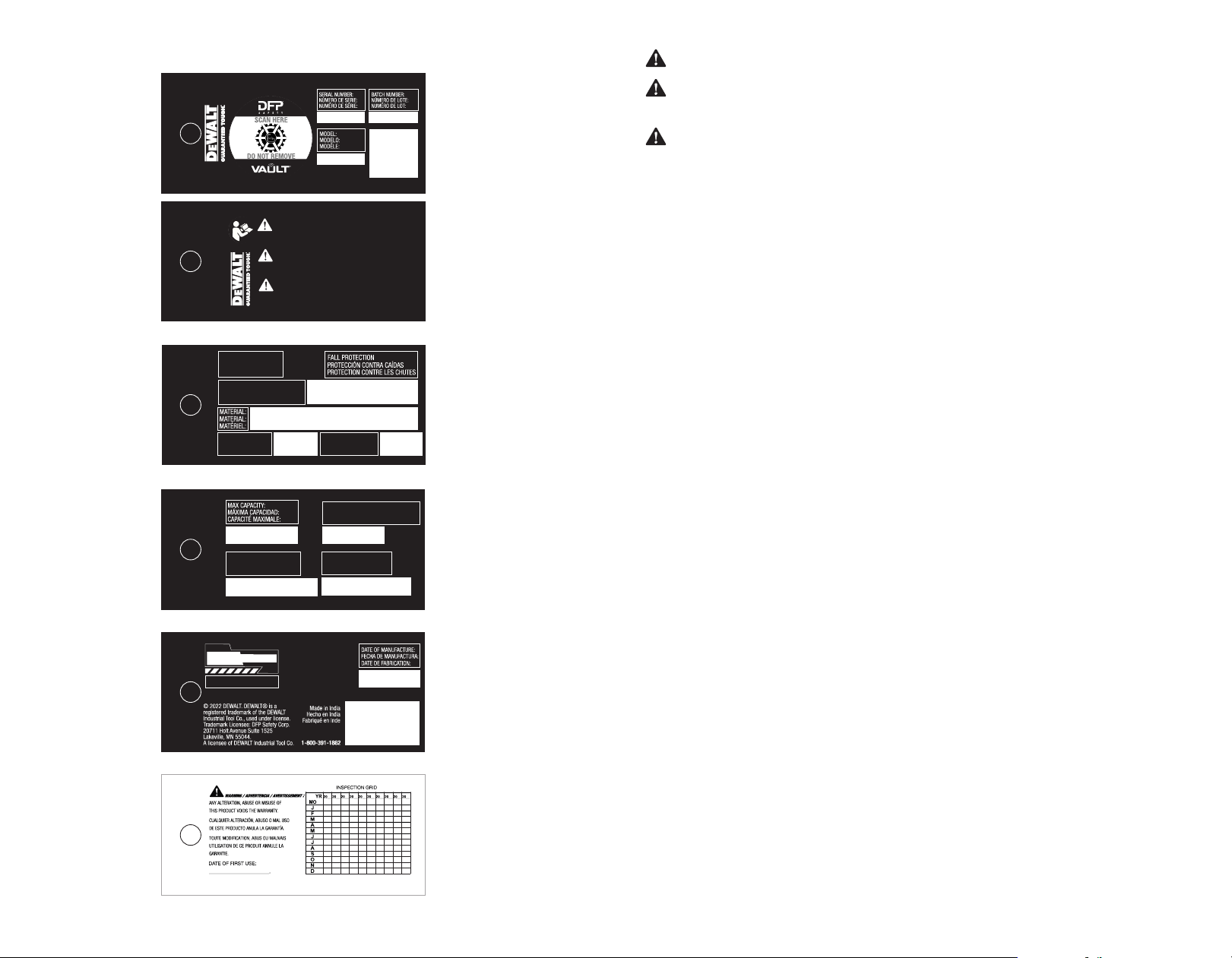
WARNING:
Prior to using the equipment, please
record the product identication information found
on the ID label of your Fall arrest equipment record
table of this manual.
a ) It is crucial that the Authorized person/user
of this fall protection equipment reads and
understands these instructions. In addition, it is
the employer's responsibility to ensure that all
users are trained in the proper use, inspection,
and maintenance of fall protection equipment.
b ) Proper use of fall arrest systems can save lives
and reduce the potential of serious injuries from
a fall.
c ) The user must be aware that forces experienced
during the arrest of a fall or prolonged
suspension may cause injury.
d ) Consult a physician if there is any question about
the user's ability to use this product.
e ) Pregnant women and minors must not use this
product.
DANGER: Do not skip this instruction manual.
Alterations or misuse of this product, or failure to follow
instructions may result in serious injury or death.
WARNING:
This product is part of a personal
fall arrest or restraint system. The user must
follow the manufacturer’s instructions for each
component of the system. These instructions must
be provided to the user of this equipment. The user
must understand these instructions before using
this equipment. Manufacturer’s instructions must
be followed for proper use and maintenance of
this product. These instructions are intended to
meet the manufacturer’s instructions as required
by OHSA, ANSI Z359.1-2007, ANSI 10.32-2012
Regulations.
a ) All warnings and instructions shall be provided
to Authorized persons/users.
b ) All Authorized persons/users must refer to the
regulations governing occupational safety, as
well as applicable ANSI standards.
c ) Please refer to product labels for information on
specific OSHA regulations, and ANSI standards
met by the product.
d ) Proper precautions should always be taken to
remove any obstructions, debris, material, or
other recognized hazards from the work area
that could cause injuries or interfere with the
operation of the system.
e ) All equipment must be inspected before each use
according to the manufacturer's instructions.
f ) All equipment should be inspected by a
Competent person on at least an annual basis.
g ) To minimize the potential for accidental disen-
gagement, a Competent person must ensure
system compatibility.
h ) Equipment must not be altered in any way.
Repairs must be performed only by the
manufacturer, or persons or entities authorized
in writing by the manufacturer.
i ) Any product exhibiting deformities, unusual
wear, or deterioration must be immediately
removed from service for inspection by Qualified
person.
j ) Any equipment subject to a fall must be removed
from service.
a ) Keep children and bystanders away while
working. Distractions can cause hazardous
conditions.
b ) The authorized person/user shall have a rescue
plan and the means at hand to implement it
when using this equipment.
c ) All synthetic material must be protected from
slag, hot sparks, open flames, or other heat
sources. The use of heat resistant materials is
recommended in these applications.
d ) Environmental hazards should be considered
when selecting fall protection equipment.
Equipment must not be exposed to chemicals
which may produce a harmful effect.
e ) Polyester should be used in certain chemical or
acidic environments. Use in highly corrosive or
caustic environments dictates a more frequent
inspection and servicing program to ensure the
integrity of the device is maintained.
f ) Do not allow equipment to come in contact
with anything that will damage it including, but
not limited to, sharp, abrasive, rough or high-
temperature surfaces, welding, heat sources,
electrical hazards, or moving machinery.
g ) Always check for obstructions below the work
area to make sure potential fall path is clear.
h ) Allow adequate fall clearance below the work
surface.
i ) Never remove product labels, which include
important warnings and information for the
authorized person/user.
4) IMPORTANT INFORMATION
5) COMPONENT COMPATIBILITY
6) COMPATIBILITY OF CONNECTORS
a ) Component compatibility with
DEWALT
manufactured fall protection equipment is
ensured by strictly following the instructions for
each type of equipment used. However, if the
user utilizes combinations of components or
sub systems that are manufactured by others,
only a “qualified” or “competent” person (as
defined in OSHA) can ensure the compatibility.
If substitutions or replacements are made with
non-approved components or sub systems, then
this may severely affect the compatibility of the
equipment, making the complete system unsafe
for use.
a ) To ensure the compatibility of the connectors
with their connecting element, it is important
to safeguard that the sizes and shapes of
the connectors and the connecting elements
do not allow their gate mechanisms to open
inadvertently, not withstanding their orientation
with each other. All hooks, carabiners, D-rings
and other such connectors must be capable
of supporting a min. force of 5000 lbs. (23
kN). All connectors must be compatible with
all system components like anchorages, etc.
Never use equipment which is not compatible
as this may cause the connectors to disengage
unintentionally. All connectors must be
compatible in shape and size. As per ANSI
Z359.12 and OSHA, only self-locking snap hooks
and carabiners may be used.
a ) Always send the equipment back to the
manufacturer, or to the persons or entities
authorized in writing by the manufacturer, for
any repairs if required. NOT all the equipment is
repairable.
b ) Never use any natural material like manila,
cotton, etc. as part of the Fall Protection System.
c ) Fall protection equipment should only be used
for the purpose for which it has been designed.
d ) This equipment should never be used for towing
and hoisting or for any other purpose than its
intended use.
e ) A competent person must ensure compatibility
of the system to minimize any potential for
accidental disengagement
f ) Users shall be trained on all warnings and
instructions provided in this manual.
g ) It is important for all Qualified, Competent and
users to refer to the applicable ANSI Standards
and to the regulations governing occupational
safety.
h ) It is important to keep in mind environmental
hazards when selecting fall protection
equipment.
i ) Extreme environments may require a more
frequent inspection and servicing program of
the fall protection equipment to maintain the
integrity and safety of the equipment.
7) CONNECTIONS USING CONNECTORS
a ) Ensure that only self-locking snap hooks and
carabiners are used with this equipment. All
connections should be compatible in size, shape
and strength. The connectors used should be
suitable to each application. Ensure that they are
fully closed and locked while in use.
WARNING: The products enumerated in this instruction manual are a part of a personal fall restraint, fall
arrest or rescue system. It is important that the user reads and follows the manufacturer’s instructions for each
component of the system. This manual contains information which is important to the user’s safety and should
be kept in a safe place for future reference as needed. The instructions provided in this manual are meant for the
use of this equipment and should be read thoroughly and understood by the user before the equipment is used.
Manufacturer’s instructions must be properly followed for the correct use and maintenance of this equipment.
Please contact DEWALT for any questions regarding use of this equipment.
WARNING: Fall arrest systems and equipment are life saving products and are designed to reduce the
potential of serious injury in the event of a fall. However, it is important to note that the user may experience an
impact of force on their body in the event of a fall. The victim of a fall may also experience adverse eects due to
prolonged suspension in a Full Body Harness (FBH). In case there is a doubt about the user’s ability to utilize this
product, the user must consult a physician. Pregnant women and minors are not considered t for the use of this
equipment
.