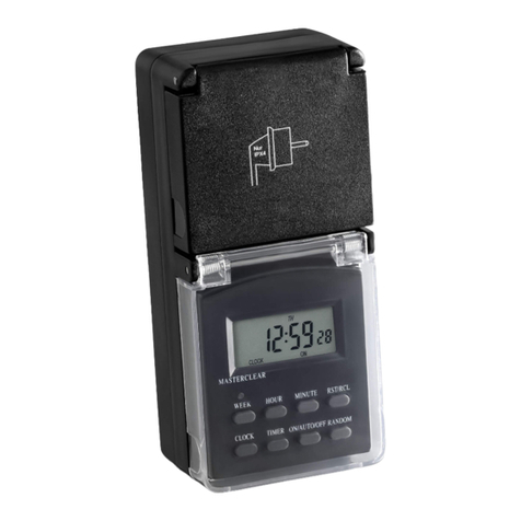
Dewenwils HODT01A User manual

Dewenwils Outdoor Digital Box Timer
N.O. Contacts:
40A Resistive, 120~277VAC
1HP, 16A FLA, 96A LRA, 120 VAC
2HP, 10A FLA, 60A LRA, 277 VAC
30A Ballast, 120VAC
20A Ballast, 277VAC
15A Tungsten, 120VAC
30A Resistive, 28VDC
N.C. Contacts:
30A Resistive, 120~277VAC
1HP, 16A FLA, 96A LRA, 120 VAC
2HP, 12A FLA, 72A LRA, 240 VAC
2A Tungsten, 120VAC
10A Ballast, 120VAC
10A Ballast, 277VAC
20A Resistive, 28VDC
CAUTION!
For outdoor use. For installation, rain-tight or wet
location conduit hubs that comply with requirements of
UL 514B Conduit, Tubing, and Cable Fittings must be used.
Note: Installation should be made by a licensed electrician.
Turn power OFF at the circuit breaker before installation.
READ ALL INSTRUCTIONS before using the outdoor digital
!
box timer
6
5
1
2
8
9
4
3
7
Operating Instruction
2. Set the DST
1. Set the Current Date
3. Set the Current Time
Button Layout
Before initial use, if the digital screen is blank, please wire it as the diagram
shows on the last paper to charge the internal battery for at least 30 minutes,
After the screen displays, the unit is ready for programming.
a. Press the “TIME” button to set the current year.
Press “+” or ”-” button to adjust the ashing number.
b. Press the “TIME” button again to set the month.
Press button “+” or “-” to adjust the number from 01 to 12.
c. Press the ”TIME” button again to set the date.
Press button “+” or “-” to adjust the number.
d.Press the “TIME” button again to set the Day
Light Savings Time (DST) function.
Press button ”+” or “-” to set AUTO, as shown in
the gure,
1. TIME – Setting the Clock.
2. RESUME – Erase Program.
3. MODE – Choose Different Mode.
4. (-) - Adjust DOWN.
5. (+) - Adjust UP.
6. PROGRAM - Setting Program.
7. RESET – Reset all the functions.
8. POWER – Power indicator light indicates if
the Digital Box Timer is turned ON or OFF.
9. STATUS – Status light indicates the output
ON.
e. Press the “TIME” button again to set the hour.
Press button “+” or “-” to adjust the number.
f. Press the “TIME” button again to set the
minutes.
Press button “+” or “-” to adjust the number
from 00 to 59.
4. Set the Astronomic Function
The map below will determine what zone the timer is being used
g. Press the “TIME” button again to set the Astronomic function.
Press button “+” or “-” to adjust three different areas to
your current location.
Once the zone is
determined, the timer
will automatically set
the sunrise and
sunset time
NO RTH
CENTRAL
SOUTH
NO RTH
CENTRAL
SOUTH
1. NORTH:
2. CENTRAL:
3. SOUTH:
h. Set the Sunrise Time
Press the “TIME” button again to adjust the Sunrise time.
Press “+” or “-” button to adjust ±2 hours,
Press “RESUME” back to current Sunrise time.
If AM twinkling it means that setting Sunrise time.
i. Set the Sunset Time
Press the “TIME” button again to adjust the Sunset time.
Press “+” or “-” button to adjust ±2 hours,
Press “RESUME” back to current Sunset time.
If PM twinkling it means that setting Sunset time.
5. Programming of Switching Times (On/Off)
Note: in the process, press the “RESUME” will clear the current
setting.
b. Press “TIME” button to set the rst On event. The setting
will begin from the begining of the week.
Press button “+” or “-” to adjust different week event:
- Every day (7 Days of the week).
- Weekday (Mon-Fri).
- Weekend (Sat-Sun).
c. Press “TIME” button to set the hours.
Press “+” or “-” to set hours. Hours setting mode:
- 12-hour clock AM/PM
- Sunrise/Sunset
Press “TIME” button to set the minutes.
Note: If you select Sunrise or Sunset as the event.
Please press “PROGRAM” button to select “ON” or “OFF”.
Press button “+” or “-” to adjust from 00-59.
Note: If you press button “RESUME” that will cancel the
setting.
d. Press “PROGRAM” button to turn the rst event OFF.
This setting is like the pervious step.There are 7 events you
can set in this timer. Once you nished the setting please
press the “PROGRAM” button back to standby status.
Note: If the timer is idle for 30 seconds. The time will automatically set to
current time.
a. Press the “PROGRAM” button to begin setting the event.

Mode
AUTO OFF
RDM ON
RDM OFF
Display Function
RDM is ON currently and
ON/OFF program is
activated
Timer is OFF currently
and ON/OFF program is
activated
RDM is OFF currently
and ON/OFF program is
activated
Mode
ON
OFF
AUTO ON
Display Function
always on
always off
Timer is ON currently and
ON/OFF program is
activated
6. Mode Setting
Press “MODE” button to choose different functions between ON, ON AUTO, ON,RANDOM(RDM), OFF, OFF AUTO, OFF RDM.
When RDM setting is ON: Random setting will increase or decrease the time on your ON/OFF setting by 30 minutes.
Dewenwils Outdoor Digital Box Timer

Dewenwils Outdoor Digital Box Timer INS TALLATION INSTRUCTIONS
!
WARNING: This timer should be installed by a licensed electrician. Turn power off at main panel before se rvicing this switch or the
equipment it controls.
IMPO RTANT: For outdoor use. Rain-tight or wet location conduit, hubs, tubing, and cable tings that comply with requirements
of UL 514B must be used for installation.
Read Important Safety Information below before beginning installatio n.
Open outer cover by releasing the spring latch.
Remove the interior protective cover by removing the two screws hold ing the cover in place (Figure 1).
Select the knockouts to be used. Remove the inner 1/2” knockout by in serting a screwdriver in
the slot and carefully punching the knockout loose. Remove slug. If 3/4” knockout is required,
also remove the outer ring with pliers after removing the 1/2” knockou t. Smooth any rough edges
with a le or sandpape r, if necessa ry.
Place the Digital Timer in the desired mounting location and mark the lo cation of the mounting
keyhole. Install a screw at mark and drive partially in place. Attach digital timer by placing keyhole
over screw; then tighten screw rml y.
Wire in accordance with national and local codes (see wiring diagram s below). Use only copper
conductors, #8 AWG wire, suitable for at least 175° F (80° C). Tighten all connections to 12in-Ibf.
Grounding: Terminate all ground wires to grounding lug at the bottom of enclosure (Figure 2).
Replace interior protective cove r.
Close outer cover and the digital timer box is ready to use.
1.
2.
3.
4.
5.
6.
7.
8.
9.
Figure 1
Figure 2
!
Important Safety Information
WARNING: Risk of Fire or Electric Shock. Read instructions thoroughly before installation and preserve for future reference.
Disconnect power at circuit breaker and test that power is off before installing (or servicing) the digital timer box (more than one circuit breaker or disconnect switch may be
required to fully disconnect power).
Wiring must be in accordance with all national and local electrical code requirements. Inspect all terminals and wires with voltage meter before touching. The maximum total
load to be controlled must not exceed Smart Box capacity.
The Digital Timer Box enclosure does not provide grounding between conduit connectors. When metallic conduit is used, you must also
install grounding type bushings and jumper wires in accordance with National Electrical Code (NEC) requirements.

DIGITAL BOX TIMER TERMINAL DESIGNATIONS
120VAC Application Controlling
One 120VAC Load
120VAC Application Controlling
Two 120VAC Loads
240VAC Application Controlling
One 240VAC Load
*J1 & J2 are 16 AWG jumper wire for the timer power supply.
277VAC Application Controlling
Two 277VAC Loads
DIGITAL BOX TIMER TYPICAL APPLICATIONWIRING DIAGRAMS
Note: Digital Box timer is capable of being congured for 120VAC, 240VAC.
L = Line | N = Neutral | NO = Normally Open | NC = Normally Closed
COM = Common Terminal | J = Jumper Wire | T = Timer
or 277VAC.
(J1)
(J1) (J2)
(J2)
(J1)
(J1) (J2)
Dewenwils Outdoor Digital Box Timer INS TALLATION INSTRUCTIONS
Made in China
HOT WATER HE ATER TYPICAL WIRING DIAGRAM
N NC2 N02 COM2 NC1 NO1 COM1
T
L
L2/N
HOT W ATER TANK
Circuit Breaker Box
240 VAC
(Dualphase)
L1
J1
J2
120 VAC
120 VAC
120 VAC
120 VAC
120 VAC
120 VAC
L1 L2
* J1 & J2 are 16 AWG jumper wire for the timer
power suppl y.
One-year Limited Warranty
Dewenwils warrants this product to be free from defects in material and workmanship for a period o f one year from the date of purchase.
Warranty will be void if damage is caused by misuse or improper installation. Please contact us if you have any questions.
Email: [email protected].
Our dedicated customer service team will get back to you within 24 hours.
Digital Box Timer
Digital Box Timer
Digital Box Timer
Digital Box Timer
Digital Box Timer
Digital Box Timer
Other Dewenwils Timer manuals

Dewenwils
Dewenwils HIDT12W User manual

Dewenwils
Dewenwils HODT13D User manual

Dewenwils
Dewenwils HODT13E User manual

Dewenwils
Dewenwils HODT21A User manual
Dewenwils
Dewenwils HOYS16A1 User manual

Dewenwils
Dewenwils HOMT11B User manual
Dewenwils
Dewenwils HOMT11A User manual
Dewenwils
Dewenwils HOYS22M User manual

Dewenwils
Dewenwils HOYS22A User manual
Dewenwils
Dewenwils HPST16M User manual


