3
User's Manual | DT200-CS
Table of Contents
Chapter 1 - Introduction................................................................................................................6
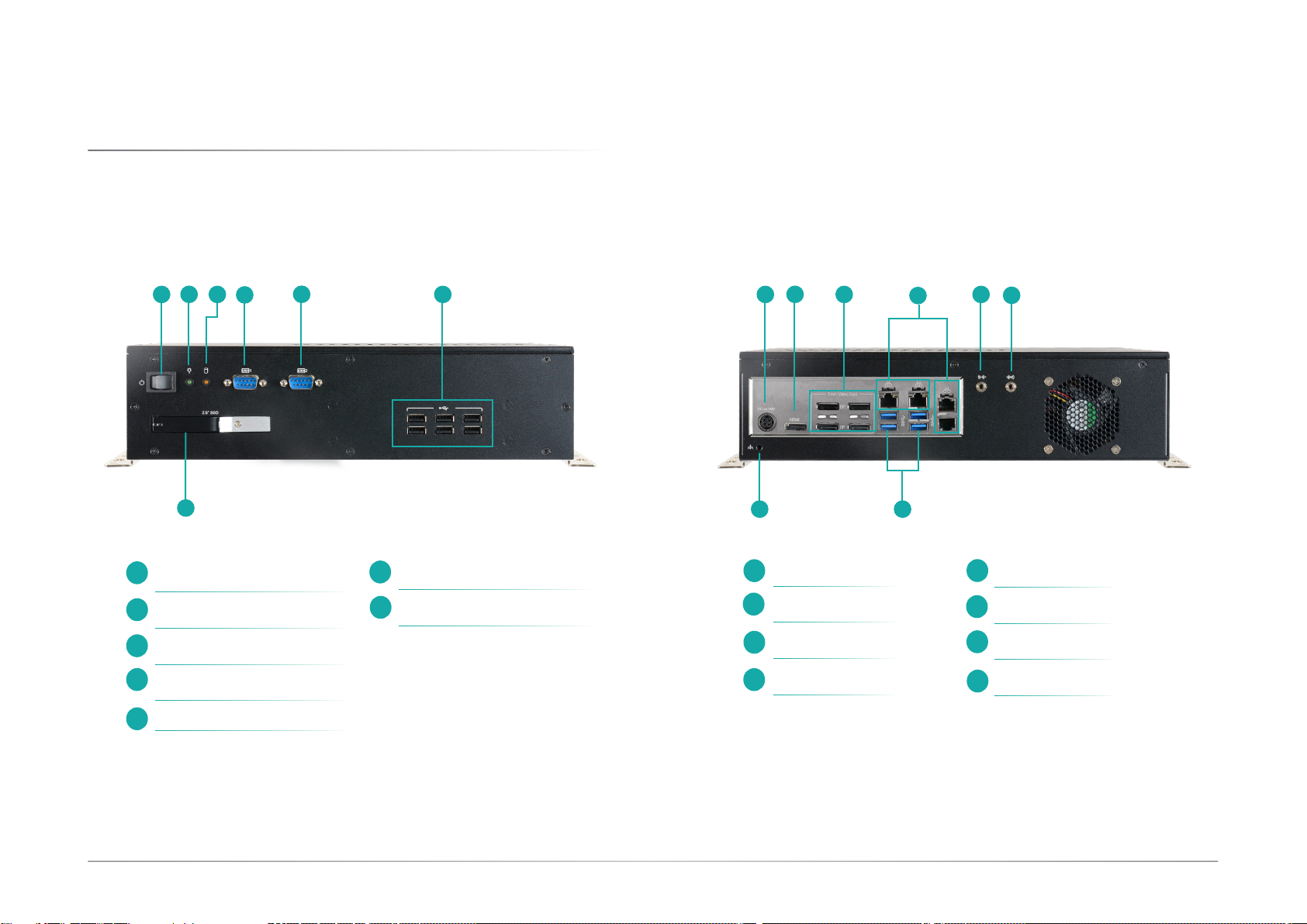
Overview.................................................................................................................................. 6
Front View ........................................................................................................................ 6
Rear View .........................................................................................................................6
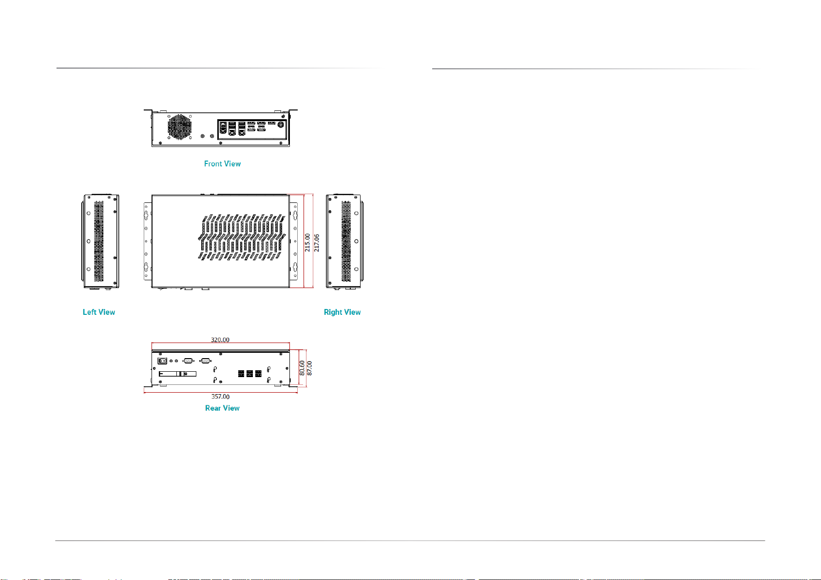
Dimensions ............................................................................................................................. 7
Key Features ........................................................................................................................... 7
Specifications ......................................................................................................................... 8
Chapter 2 - Hardware Installations............................................................................................10
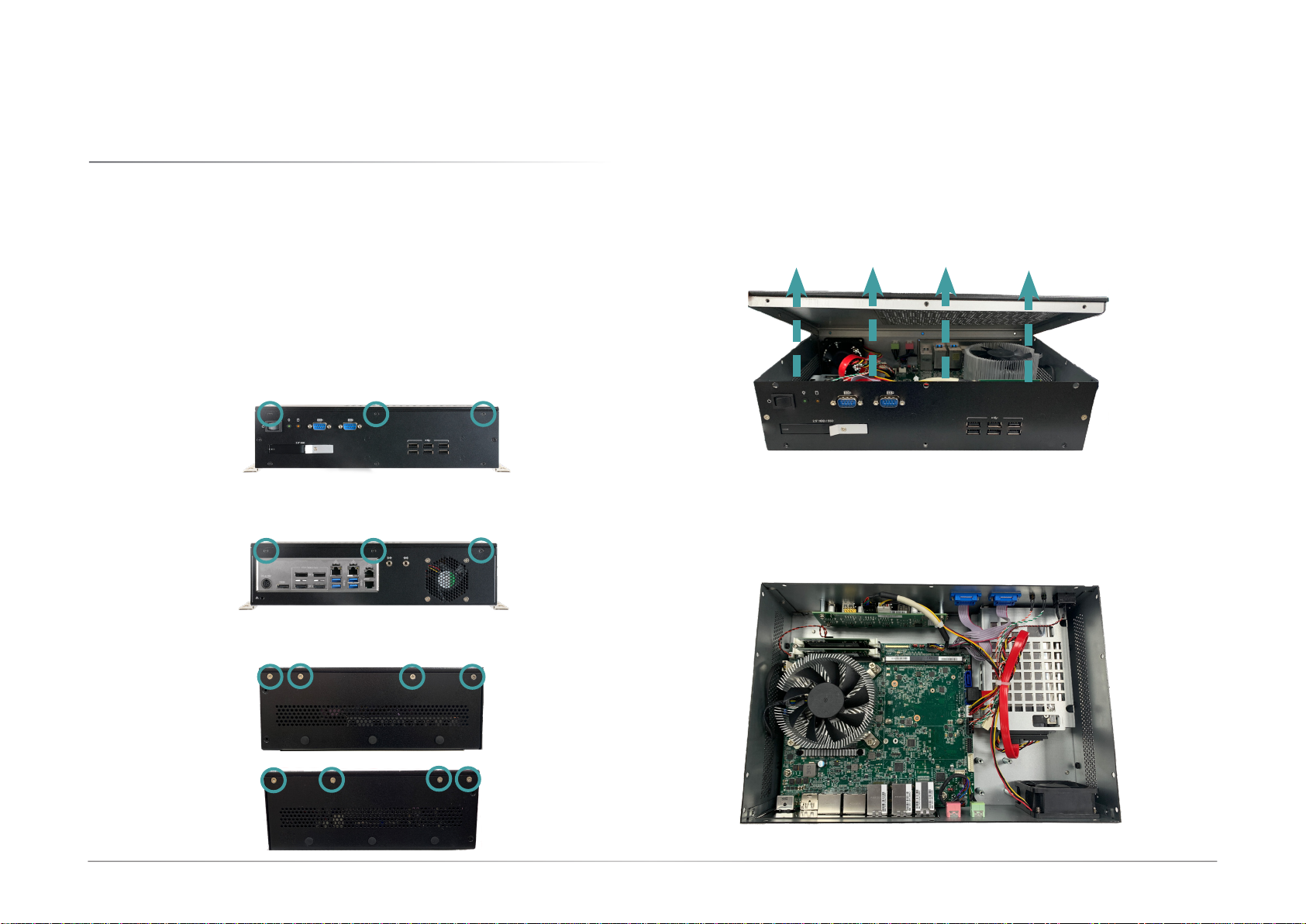
Removing the Chassis Cover ..............................................................................................10
Front View ......................................................................................................................10
Rear View .......................................................................................................................10
Left View ........................................................................................................................10
Right View ......................................................................................................................10
Installing an M.2 Card .........................................................................................................11
Installing an MXM Card .......................................................................................................12
Installing an Antenna ...........................................................................................................16
Insterting a 2.5" HDD/SDD .................................................................................................17
Mounting Options.................................................................................................................18
Wall Mount .....................................................................................................................18
Chapter 3 - System Settings ......................................................................................................19
System Layout......................................................................................................................19
Jumper Settings ...................................................................................................................20
Clear CMOS Jumper......................................................................................................20
M.2 Power ......................................................................................................................20
Pin Assignment ....................................................................................................................21
CPU Fan .........................................................................................................................21
USB2_5/6........................................................................................................................21
COM (Serial) Port ..........................................................................................................22
Front Panel.....................................................................................................................22
LPC .................................................................................................................................23
DIO (Digital I/O) .............................................................................................................23
DIO Power ......................................................................................................................24
Front Audio ....................................................................................................................24
SATA Power ...................................................................................................................25
SATA (Serial ATA) .........................................................................................................25
Chapter 4 - BIOS Settings...........................................................................................................26
Overview ...............................................................................................................................26
Main.......................................................................................................................................27
Advanced .............................................................................................................................27
RC ACPI Configuration..................................................................................................28
CPU Configuration.........................................................................................................28
Power & Performance ...................................................................................................29
PCH-FW Configuration ..................................................................................................29
Trusted Computing........................................................................................................30
NCT5525D Super IO Configuration ..............................................................................30
NCT5525D Super IO Configuration ►Serial Port 1, 2 Configuration ..................31
NCT5525D HW Monitor ................................................................................................31
NCT5525D HW Monitor ►Smart FAN Function .................................................32
Serial Port Console Redirection ...................................................................................32
Serial Port Console Redirection ►Console Redirection Settings........................33
USB Configuration .........................................................................................................33
CSM Configuration ........................................................................................................34
USB Power Control........................................................................................................34
Network Stack Configuration........................................................................................35
Chipset ..................................................................................................................................36
Graphics Configuration .................................................................................................36
PEG Port Configuration.................................................................................................37
PEG Port Configuration ►PEG Port Feature Configuration................................37
PCH-IO Configuration ....................................................................................................38
PCH-IO Configuration ►PCI Express Configuration...........................................39
PCH-IO Configuration ►SATA And RST Configuration.......................................39
PCH-IO Configuration ► HD Audio Configuration..............................................40
Security .................................................................................................................................41
Secure Boot....................................................................................................................41
Boot .......................................................................................................................................42
Save & Exit ............................................................................................................................42
Updating the BIOS................................................................................................................43
Notice: BIOS SPI ROM..........................................................................................................43