Dialight L-856 Manual
Document: 9100-127-2905-99
Revision B
Release Date: 1/23/2017
Dialight Corporat ion 1501 Route 34 South Farmingdale NJ 07727
Tel: 732.919.3119 Fax: 732.751.577 8 Web: www.dialight.com
INSTALLATION AND MAINTENANCE MANUAL
FOR
L-856 / L-864 High Intensity Strobe
D266-A57-CTR-AC
(Base Controller)
D266-A57-270 (Power Supply and Flash Head)

Document: 9100-127-2905-99
Revision B
Release Date: 1/23/2017
Dialight Corporation 1501 Route 34 South Farmingdale, NJ 07727
Tel: 732.919.3119 Fax: 732.751.5778 Web: www.dialight.com
Page 2 of 40
CONTENTS PAGE
Notice and Warnings --------------------------------------------------------------------------------- 3
Product Overview-------------------------------------------------------------------------------------- 4
Terminology --------------------------------------------------------------------------------------------- 6
Getting Started ----------------------------------------------------------------------------------------- 7
Section 1.0: Tower Preparation------------------------------------------------------------------ 7
Section 2.0: Choosing a circuit breaker ------------------------------------------------------- 8
Section 3.0: Base Controller Preparation ---------------------------------------------------- 9
Section 4.0: Photocell Installation -------------------------------------------------------------11
Section 5.0: OB or L810 Connections ---------------------------------------------------------12
Section 6.0: Sync Input (with Optional GPS Hardware) --------------------------------12
Section 7.0: Sync Output (with Optional GPS Hardware)------------------------------13
Section 8.0: AOL Enable / Disable -------------------------------------------------------------13
Section 9.0: Adding Additional Interfaces --------------------------------------------------13
Section 10.0: Photocell Validation-------------------------------------------------------------14
Section 11.0: Initial Power Supply Preparation -------------------------------------------15
Section 12.0: Power Supply Addressing ----------------------------------------------------16
Section 13.0: Power Supply Cable Definition & DC Connections-------------------18
Section 14.0: Flash Head Communication Connections-------------------------------22
Section 15.0: Other Power Supply Preparation -------------------------------------------22
Section 17.0: Mounting Power Supply Enclosures --------------------------------------25
Section 18.0: Mounting Flash Heads----------------------------------------------------------27
Section 20.0: System Power Up ----------------------------------------------------------------31
Section 21.0: Alarm Relays-----------------------------------------------------------------------31
Section 22.0: Additional Information ----------------------------------------------------------33
Section 23.0: Troubleshooting-------------------------------------------------------------------33
Section 24.0: System Specifications-----------------------------------------------------------38

Document: 9100-127-2905-99
Revision B
Release Date: 1/23/2017
Dialight Corporation 1501 Route 34 South Farmingdale, NJ 07727
Tel: 732.919.3119 Fax: 732.751.5778 Web: www.dialight.com
Page 3 of 40
Notice and Warnings
This manual contains important information regarding the proper installation, operation, and
maintenance of this product. Before using the product, read and understand all instructions,
cautions, and warnings; as well as all of the labels affixed to the product. Failure to do so
could result in personal injury or damage to the equipment, and/or void the product warranty.
FAILURE TO LEAVE THE ENCLOSURES FREE FROM DEBRIS UPON COMPLETION OF
INSTALLATION MAY CAUSE SHORT CIRCUITS AND VOID THE SYSTEM WARRANY.
FAILURE TO TIGHTEN DOWN CLAMP WASHERS WILL MAKE INTERNAL COMPONENTS
VULNERABLE TO SURGE OR LIGHTNING DAMAGE AND VOID THE SYSTEM WARRANY.
FAILURE TO PROPERLY BOND THE EARTH GROUND WIRE TO THE JUNCTION BOX WILL
RESULT IN EVENTUAL LIGHTNING DAMAGE OF THIS SYSTEM.TO AVOID WARRANTY
NULLIFICATION,FOLLOW ALL DIRECTIONS IN THEIR ENTIRETY.
CAUTION:PHOTOCELL ONLY TO BE CONNECTED TO MONITOR BOARD USING
TERMINAL BLOCKS PROVIDED
WARNING:FAILURE TO PROPERLY BOND THE FLASH HEADS AND POWER SUPPLY
ENCLOSURES TO THE TOWER STRUCTURE WILL RESULT IN EVENTUAL LIGHTNING
DAMAGE OF THIS SYSTEM.THE SYSTEM’S WARRANTY SHALL BE VOID IF ALL FLASH
HEADS AND POWER SUPPLY ENCLOSURES ARE NOT PROPERLY BONDED TO THE TOWER
STRUCTURE.TO AVOID WARRANTY NULLIFICATION,FOLLOW ALL DIRECTIONS IN
THEIR ENTIRETY.
CAUTION:NEVER LOOK AT THE FRONT OF A FLASH HEAD WHILE THE SYSTEM IS
ENERGIZED.THE FLASH HEAD COULD START FLASHING CAUSING TEMPORARY
BLINDNESS WHICH WOULD BE DANGEROUS AT HIGH ELEVATIONS.

Document: 9100-127-2905-99
Revision B
Release Date: 1/23/2017
Dialight Corporation 1501 Route 34 South Farmingdale, NJ 07727
Tel: 732.919.3119 Fax: 732.751.5778 Web: www.dialight.com
Page 4 of 40
FAILURE TO SET UP SYSTEM CORRECTLY DURING START UP WILL RESULT IN THE
TOWER HAVING TO BE CLIMBED AGAIN TO PERFORM TROUBLESHOOTING.
DIALIGHT CORPORTATION DOES NOT WARANTEE THE HIGH INTENSITY SYSTEM WHEN
USING IT WITH A TEMPORARY POWER SOURCE.
DIALIGHT CORPORTATION DOES REQUIRE PICTURES OF THE INSTALLATION FOR
COMMISIONING PURPOSES.FAILURE TO DO WILL VOID ALL ALL WARRANTIES.
THE SITE MANAGER OR OWNER MUST SUPPLY RECENT PICTURES OF THE STRUCTURE
TO ENSURE ACCURACY OF THE LIGHTING SYSTEM AND HARDWARE SUPPLIED.
ADEQUATE WIRING GAUGES AND BREAKER SIZES ARE THE RESPONSIBILITY OF THE
SUPPLIER OF THE SYSTEM.
SPECIAL CONSIDERATIONS ARE REQUIRED FOR INSTALLING ON HOT AM TOWERS.
CONTACT THE SUPPLIER OF THE SYSTEM WHEN IN DOUBT.
AC INPUT TOLERANCES ARE A MAXIMUM OF +/-10% OF THE NOMINAL VOLTAGES
SHOWN IN THE MANUAL

Document: 9100-127-2905-99
Revision B
Release Date: 1/23/2017
Dialight Corporation 1501 Route 34 South Farmingdale, NJ 07727
Tel: 732.919.3119 Fax: 732.751.5778 Web: www.dialight.com
Page 5 of 40
Product Overview
The Dialight L-856 / L-864 High Intensity White / Red Strobe System, herein referred
to as the System, is designed to for the lighting of tall structures such as television and radio
towers, chimneys, cooling towers, tall buildings, wind generators and other obstructions to
aerial navigation, per specification by the FAA.
This product uses LED technology within each Flash Head to produce white strobe
light. Unlike conventional xenon flashtube technology, little or no maintenance is required
during the lifetime of this System. Working voltages within this System never exceed 200
Volts DC. Therefore by significantly lowering the working voltage with respect to Xenon white
strobes, this System represents an advance in obstruction lighting safety and efficiency.
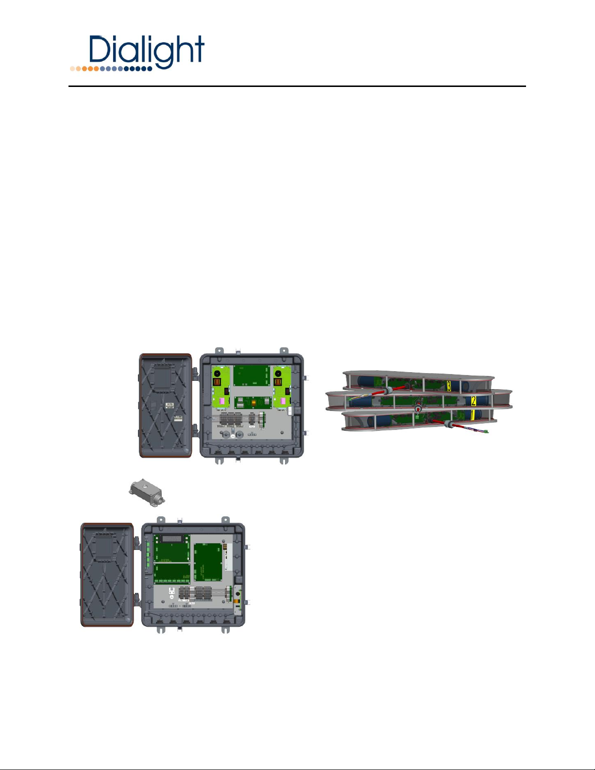
One Base Controller Enclosure is required to enable the System regardless of system
scale. For example a System with three Flash Heads and a System with eighteen Flash
Heads both need the same Base Controller Enclosure to operate.
With the use and proper setup of the Base Controller each of the below systems can
be configured through the LCD display.
White Only System
The System may comprise up to eighteen L-856 High Intensity White Strobe Flash
Heads; each with a corresponding Power Supply Enclosure, e.g. one Power Supply
Enclosure per Flash Head. The Flash Heads are typically distributed as three per level on up
to six levels, for a maximum of eighteen Flash Heads.
Red/White System
The System may comprise up to eighteen L-856/864 High IntensityWhite Strobe Flash
Heads which have the RED L-864 included in each of the LED modules. Each has a
corresponding Power Supply Enclosure, e.g. one Power Supply Enclosure per Flash Head.
The Flash Heads are typically distributed as three per level on up to six levels, for a maximum
of eighteen Flash Heads. L810 Marker Lights are also monitored through the base controller.
AOL Strobe
Additionally, one L-864/L-865 Medium Intensity Strobe may be integrated into the
system as an Antenna Obstruction Light (AOL). The Base Controller will synchronize,
monitor, and control the entire System, as well the Antenna Obstruction Lights.

Document: 9100-127-2905-99
Revision B
Release Date: 1/23/2017
Dialight Corporation 1501 Route 34 South Farmingdale, NJ 07727
Tel: 732.919.3119 Fax: 732.751.5778 Web: www.dialight.com
Page 6 of 40
Terminology
The following definitions apply to the System:
L856
FAA classification of a flashing white High Intensity Obstruction Light, 40 FPM
L864
FAA classification of a flashing Red Medium Intensity Obstruction Light, 20-30 FPM
L810
FAA classification of a Red Steady Burning Obstruction Light
Base Controller
Master Control Cabinet
LCD Screen
Liquid Crystal Display; forty character module
Micro Board
Printed circuit board with onboard micro controller
Relay Board
Provides 8 external connections for alarm status and monitoring
Alarms
Alarm faults that need to verified and corrected, NOTAM must be reported
Events
Events are notice to the site manager that an “event” occurred but has NOT caused
an alarm. I.E. power on, Power Supply was turned off. These are also used to
troubleshoot alarms.
Power Supply
Enclosure mounted to the tower controlling the individual Flash Head
Dip Switches
Located in Power Supplies to assign addresses to Flash Heads
Flash Head
The 3 individual Flash LED Modules mounted together
Flash “LED” Module
The individual module numbered 1, 2or 3 containing the LED’s and reflectors
PEC Mode
Flash intensity based on outdoor ambient light condition
Heartbeat
Blinking LED which indicates a Micro Board is healthy. NOTE: Located in both the
Base Controller and Power Supply
Red System
When properly configured through the main micro provides RED at night operation
AOL
Antenna Obstruction Light, also can be added through the Base Controller
Synchronization
All lights flash simultaneously to the human eye
Communication
RS485 signals between Controller, Power Supply and Flash Head
25% Failure
Alarm occurs when greater than 25% of a single Flash Head is out, monitors for
both in Red operation and white operation
The System
The lighting, hardware, wiring and any other materials required for installing the
system.

Document: 9100-127-2905-99
Revision B
Release Date: 1/23/2017
Dialight Corporation 1501 Route 34 South Farmingdale, NJ 07727
Tel: 732.919.3119 Fax: 732.751.5778 Web: www.dialight.com
Page 7 of 40
Getting Started
Carefully unpack and take inventory of all system components before beginning the
following steps. Flash Heads and Power Supply Enclosures come in separate boxes. They
must be paired together and laid out in a clean work area.
Parts Typically Supplied:
1: 1 Base Controller
2: 3 or More LED Flash Heads (Consisting of 3 modules factory secured together)
3: 3 or More Flash Head Power Supply enclosures
4: Spare Parts Kit(s)
5: This manual
6: Quick start Manual (For configuring the Base Controller)
NOT Supplied with this Manual is the site specific wiring diagram. This is supplied by the
seller of the system.
Section 1.0: Tower Preparation
It is recommended that the tower on which the System is to be installed be inspected
prior the installation.
1: If using existing junction boxes, they should be opened and checked for leaks.
2: If re-using wiring from an existing system it must be checked at this time for ratings, breaks,
oxidation and other damage that could cause electrical issues during the installation and
operation. Failures in the wiring during or after the installation are the responsibility of the Site
Manager and the owner of the structure.
NOTE: It is recommended that any reused existing cable has the bare wire cut far enough
back to expose clean copper. If this is not possible then the cabling MUST be replaced.
3: The Dialight High Intensity system uses RS485 for communications. The signal integrity,
ratings and wire gauge should be verified before installing this system.
4: The Base Controller and Power Supply enclosures have terminal blocks for AC wiring that
can accept up to 8 gauge (8AWG) wires.
NOTE: Do not use less than 14 gauge (14AWG) mains cord for powering the system. Refer
to electrical specifications below for further details.
Document: 9100-127-2905-99
Revision B
Release Date: 1/23/2017
Dialight Corporation 1501 Route 34 South Farmingdale, NJ 07727
Tel: 732.919.3119 Fax: 732.751.5778 Web: www.dialight.com
Page 8 of 40
Section 2.0: Choosing a circuit breaker
Also refer to the wiring diagram that is sent with the cables and hardware for site
specific information. This information is required to be sent by the system provider or the
hardware provider.
For the purpose of sizing tower conductor gauges and circuit breakers follow the table
and formula below. Input current is inversely proportional to supply voltage, so low supply
voltages result in higher input currents. It is the responsibility of the system supplier to
calculate the required cable gauges and breaker sizes.
All tolerances are +/- 10% from nominal voltages shown below.
Measurements are actual measurements and not scaled in any matter
Nominal Supply Voltage /Freq
(VAC)/Hz
RMS Current (A) per Flash
Head
Peak Current (A) per Flash
Head
208 / 60Hz
1.12
2.18
240 /50Hz
.96
1.98
277 /60Hz
.87
1.68
Table 1 - High Intensity Strobe Current Ratings
Find the voltage you are planning to run the System in the table above; then multiply
the number of Flash Heads on the System times the RMS current to find the total operating
current. Also multiply the number of Flash Heads on the System times the peak current to
find the total peak current.
If using a Dialight DR1W strobe as an AOL, then you must add the current of the AOL
to the total calculated below if the AOL is to be powered off the same breaker.
Nominal Supply Voltage
(VAC)
RMS Current (A) for AOL
Peak Current (A) for AOL
208
0.8
1.3
240
0.50
0.8
277
0.50
0.8
Table 2 - AOL (D1RW) Current Ratings
WARNING:The above tables arefor individual Flash Heads and the AOL. The system power
requirements must be calculated.
WARNING: It is recommended that no more than 80% of the breaker rating is used.
Document: 9100-127-2905-99
Revision B
Release Date: 1/23/2017
Dialight Corporation 1501 Route 34 South Farmingdale, NJ 07727
Tel: 732.919.3119 Fax: 732.751.5778 Web: www.dialight.com
Page 9 of 40
Section 3.0: Base Controller Preparation
The Base Controller should be permanently mounted in a location which has easy
access for inspections or upgrades.
The Base Controller can be energized from the same circuit breaker as the Power
Supply Enclosures, or it can be run from a different voltage or breaker. In the case of different
voltages and breakers, it is recommended that the Power Supplies be powered up first, then
the Base Controller. This will only be required during the installation process and configuring
the system. Thus it is preferred that the Base Controller be on its own breaker.
Base Controller Electrical Parameters:
NOTE: This is only for the High Intensity Base Controller
NOTE: Only the Base controller can run from 120Vac
WARNING: Power Supplies/Flash Heads can NOT properly operate from 120VAC.
Nominal Supply Voltage
(VAC) Hz
Watts
Information
120 +/-10% Max 50/60Hz
6.5
Can only be used if Controller
has its own power
208 +/-10% Max 50/60Hz
6.5
240 +/-10% Max 50/60Hz
6.5
277 +/-10% Max 50/60Hz
6.5
Table 3 - AOL (D1RW) Base Controller Electrical Parameters
The following steps are recommended for a successful installation:
The Base Controller can be mounted to any sufficient location the installer/electrician
sees fit. The dimensions are given below. If the Base Controller is to be mounted to an exterior
structure such as the tower, then special grounding considerations must be adhered to avoid
voided warranties. See Section 17.0 for further details.
For exterior mounting it is suggested that the conduit or glands be mounted on the
bottom of the enclosure using holes provided by Dialight to ensure a weather tight seal for
the life of the product.

Document: 9100-127-2905-99
Revision B
Release Date: 1/23/2017
Dialight Corporation 1501 Route 34 South Farmingdale, NJ 07727
Tel: 732.919.3119 Fax: 732.751.5778 Web: www.dialight.com
Page 10 of 40
NOTE: If there is a possibility of water or condensation entering through the conduit or cables,
the installer must take all necessary precautions to prevent water entering the enclosure.
Failure to do so will void all warranties. Cable loops and drain plugs must be added to the
system as seen fit. If in doubt, please contact www.dialight.com or the system provider.
For cable loops it is suggested that a minimum of 3 to 4 loops with a diameter of 12
inches are used.
Drain plugs should be located at the bottom of any conduit run and or at the lowest
point of the conduit run.
For horizontal conduit runs it is required that the conduit be tilted or angled toward
junction boxes that have drain plugs. Conduit should not tilt downwards to un-drained
enclosures or to breaker panels.
Refer to the Quick Start Manual for information regarding connection of AC power and
RS485 Communications.
Spacing of the mounting tabs is shown below:
Open the Base Controller enclosure and set aside any spare parts bags.
Document: 9100-127-2905-99
Revision B
Release Date: 1/23/2017
Dialight Corporation 1501 Route 34 South Farmingdale, NJ 07727
Tel: 732.919.3119 Fax: 732.751.5778 Web: www.dialight.com
Page 11 of 40
NOTE: Some spare parts included in this bag may be required for the fixtures being
mounted on the structure
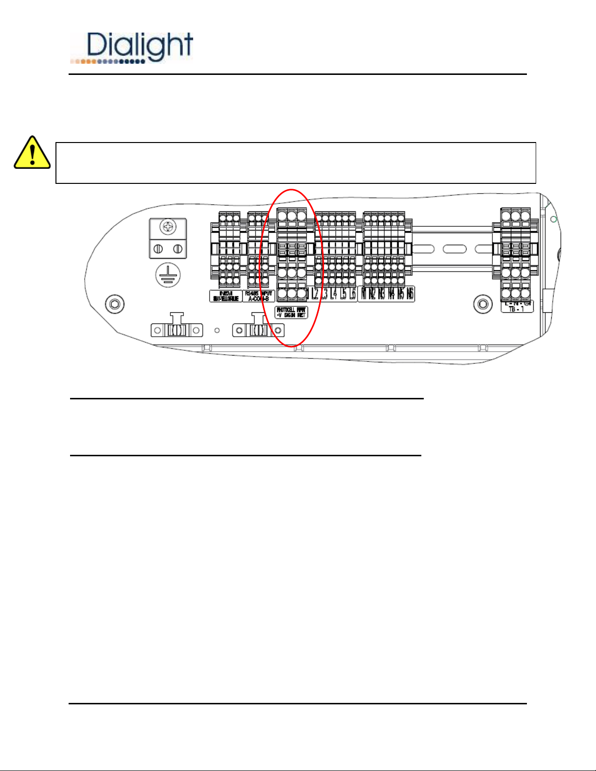
Section 4.0: Photocell Installation
NOTE: See the Photocell manual included in itspackaging box for connections and additional
information.
Cable Requirements:
NOTE: The connection cord to the photocell is required to be 3 conductors of 18 to 14
gauge stranded wire. Refer to structure’s wiring diagram supplied with the hardware kit.
A separate ¾” conduit must be run for the Photocell to connect to the Base Controller.
A single Photocell is required for transitioning between day, twilight and night modes. The
Photocell is pre-calibrated to the correct trigger light intensity. No additional adjustments are
required.
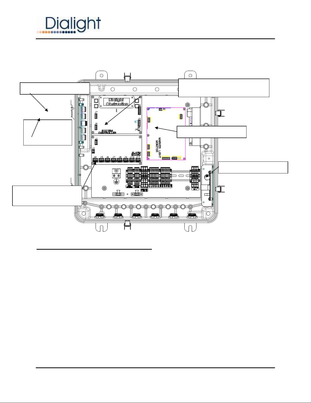
When mounting, it is important to orientate the Photocell so that it faces north with no
obstructions. The Photocell is powered by the Base Controller through the Monitor Board
and no additional power is required as shown below.
Dry Contact Relay
Board
RS485
Junction Board
Filter / Surge Board
48V Power Supply
L810 Monitor & Photocell
Control Board
Main Controller Board
Document: 9100-127-2905-99
Revision B
Release Date: 1/23/2017
Dialight Corporation 1501 Route 34 South Farmingdale, NJ 07727
Tel: 732.919.3119 Fax: 732.751.5778 Web: www.dialight.com
Page 12 of 40
NOTE: Only Dialight Photocells can be used with this system
NOTE: Additional Photocell relay testing will be included in Section 10.0 of this manual.
CAUTION:PHOTOCELLS ARE TO BE CONNECTED TO J4 OF THE MONITOR BOARD ONLY
USING THE DIN RAIL TERMINAL BLOCKS IN THE CONTROLLER ENCLOSURE
Section 5.0: RED Side lights (OB) or L810 Connections
Refer to Quick Start manual for instructions to calibrate and connect side lights to the
System.
Section 6.0: Sync Input (with Optional GPS Hardware)
This connection will synchronize the System with either a GPS controller or another
local Base Controller. The contact looks for a pulsed signal with a period of 1,500
milliseconds, where the leading edge to falling edge of the pulse is greater than 100
milliseconds. This will trigger forty flashes per minute synchronized with the other system’s
output.In order for the system to work with a GPS controller the Base Controller must be
configured through the “config” setup screens. See the Quick Start Manual for details and set
up.
NOTE: The maximum distance between the Base Controller and the device receiving the
sync signal is 50 feet. If longer distances are required please contact www.dialight.com.

Document: 9100-127-2905-99
Revision B
Release Date: 1/23/2017
Dialight Corporation 1501 Route 34 South Farmingdale, NJ 07727
Tel: 732.919.3119 Fax: 732.751.5778 Web: www.dialight.com
Page 13 of 40
NOTE: Be sure the GPS antenna is located at an adequate height and does not have
obstructed views of the sky when selecting a location.
Section 7.0: Sync Output (with Optional GPS Hardware)
This connection will synchronize the System to another local Base Controller. The
contact generates a pulsed signal with a period of 1,500 milliseconds, where the leading edge
to falling edge of the pulse is approximately 100 milliseconds.
The System generates this output in all operational modes after startup.
This connection would be typically used when 2 structures are situated side by side and
requires both structures to flash simultaneously.
NOTE: 2 Base Controllers are required for this option
NOTE: If a single Base Controller is used then the RS485 or a sync cable can be ran between
structures. There are no further details in this manual for this connection, please contact
www.dialight.com for connections, maximum distances and more information.
Section 8.0: AOL Enable / Disable
An AOL light can be added to the System at anytime by way of RS485
communications. By connecting RS485 from the AOL Power Supply to the last junction box
and the Base Controller configured for the AOL, the system then will control the AOL.
WARNING: The AOL must be an approved Dialight version or delivered from one of their
partners.
WARNING: Refer to the AOL instruction manual for wiring and mounting.
To enable the use of an AOL requires configuration through the config screen. See the Quick
Start Manual for setup.
Section 9.0: Adding Additional Interfaces
If at a later date an AOL is required for the structure that has this system already
installed then just the AC connection and a link in to the RS485 bus is required for connecting.
Once installed the Base Controller requires configuring for AOL. Only a single AOL can be
added to the system. Multiple AOL’s can not be added. The AOL must be fed from the same
AC power source as feeding the lights.

Document: 9100-127-2905-99
Revision B
Release Date: 1/23/2017
Dialight Corporation 1501 Route 34 South Farmingdale, NJ 07727
Tel: 732.919.3119 Fax: 732.751.5778 Web: www.dialight.com
Page 14 of 40
Section 10.0: Photocell Validation
Perform the following to make sure the Photocell is correctly connected and controlling the
System mode.
1. NOTE: This can be done as a stand alone test; no Flash Heads are required to be
powered.
2. Turn on the Base Controller, and using the up/down arrows go to the “alarm screen”
3. On the Monitor Board confirm LED Photo_Fault is not lit.
If the LED is lit RED then the Photocell is not being detected and wiring and
connections must be confirmed before continuing the testing of the Photocell.
4. Remove the Phoenix connector that connects the 3 wires that go to the Photocell.
Located on the Monitor Board J4.
5. The status alarm must go from “normal” to alarm and by selecting the “ent” button the
last alarm will be PEC lost “act”.
6. A red LED labeled LED Photo_Fault on the monitor board will be turned on this
indicates there is no Photocell detected.
7. Re-install the Photocell J4 and the LED will be turned off and then by pressing the up
arrow the next entry will be PEC lost “Clr” which means the Photocell is detected.
For testing the actual operation of the Photocell it is required that the Photocell be
covered to indicate night mode operation.
NOTE: Since twilight mode is triggered between day and night mode, only day and night
mode are required to be tested to ensure proper operation of the Photocell.
1: With the Base Controller powered on, using the up/down arrows select the Mode screen.
2: Verify the present mode which will be day, twilight or night
NOTE: If the present mode is not shown it is due to the connections of the Photocell not being
correct.
3: If the System mode is day then simply covering the Photocell with a glove will change the
state of the Photocell to twilight then night.
NOTE: There is a factory default setting of approximately 1 minute before switching modes.
If the system mode is shown as night then a flash light focused on the Photocell can be used
to change the state of the system to day.
Document: 9100-127-2905-99
Revision B
Release Date: 1/23/2017
Dialight Corporation 1501 Route 34 South Farmingdale, NJ 07727
Tel: 732.919.3119 Fax: 732.751.5778 Web: www.dialight.com
Page 15 of 40
WARNING: If Flash Heads are connected then the structure will go to 270,000cd day mode
and changing back has a 1 minute delay.
WARNING: If the Photocell is removed or not connected properly all Flash Heads will operate
in night mode based on if the system is set for red night or white night.
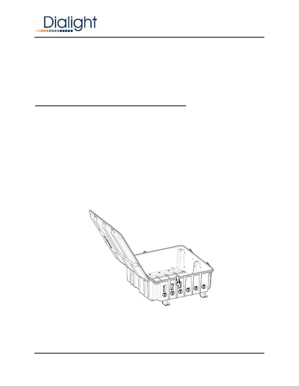
Section 11.0: Initial Power Supply Preparation
The Power Supply Enclosure requires the most field wiring and should be configured
and reviewed before being brought up the tower.
At the bottom of the enclosure there are six factory installed holes. 3 of these
are for connection to the Flash Head and 1 for AC mains and RS485 communications
cable. The AC and RS485 can be run together and must be in seal tight or conduit.
Unused holes must remain plugged to maintain ingress protection ratings.
NOTE: If for some un-foreseen reason additional holes are required for the
installation. Contact the seller of the system or Dialight for instructions.
NOTE: The AC and RS485 can be run together and must be in seal tight or conduit.
The enclosure comes with mounting tabs that are to be joined to the body of the
tower.
Document: 9100-127-2905-99
Revision B
Release Date: 1/23/2017
Dialight Corporation 1501 Route 34 South Farmingdale, NJ 07727
Tel: 732.919.3119 Fax: 732.751.5778 Web: www.dialight.com
Page 16 of 40
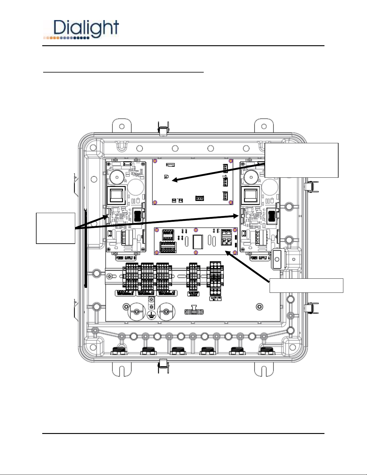
Section 12.0: Power Supply Addressing
Open the enclosure and orientate your view to match the illustration shown below. On
the Micro Board there is a DIP switch array designated as SW1. This is the addressing switch
used to identify this Power Supply Enclosure / Flash Head on the system.
P/S Micro Board
DIP switch SW1 for
setting addresses of
the Power Supply
Filter/Surge Board
150V
Power
Supplies

Document: 9100-127-2905-99
Revision B
Release Date: 1/23/2017
Dialight Corporation 1501 Route 34 South Farmingdale, NJ 07727
Tel: 732.919.3119 Fax: 732.751.5778 Web: www.dialight.com
Page 17 of 40
The default factory address is 1. One of the Power Supply Enclosures must be
set as address 1. The addresses of all other Power Supply Enclosures must be
changed. The inside of the enclosure will have a sticker showing all the possible
address positions for switch SW1.
WARNING: No two Power Supplies can have the same address setting.
If duplicate settings are made then configuration errors will be shown in the event
log. Flip the DIP switches on SW1 to match the desired address for that Power
Supply location, as shown below, and then immediately mark the inner label with an
Xin permanent marker as to which address was set. The enclosure should be closed
up tightly before being lifted to the mounting location. Therefore before mounting the
address should also be written on the outside of the enclosure with a grease pencil
or marker.
NOTE: Typical installations are that Power Supply #1 is located on the lowest level
and mounted to the Northern most leg. Looking down from the top of the structure
counting clockwise the next is 2 and the next is 3. So that above #1 is #4 and above
that is #7 and so one.
NOTE: This is required unless the Site manager wants something different than the
above states.
NOTE: Refer to the below and section 23.0 for additional information.

Document: 9100-127-2905-99
Revision B
Release Date: 1/23/2017
Dialight Corporation 1501 Route 34 South Farmingdale, NJ 07727
Tel: 732.919.3119 Fax: 732.751.5778 Web: www.dialight.com
Page 18 of 40
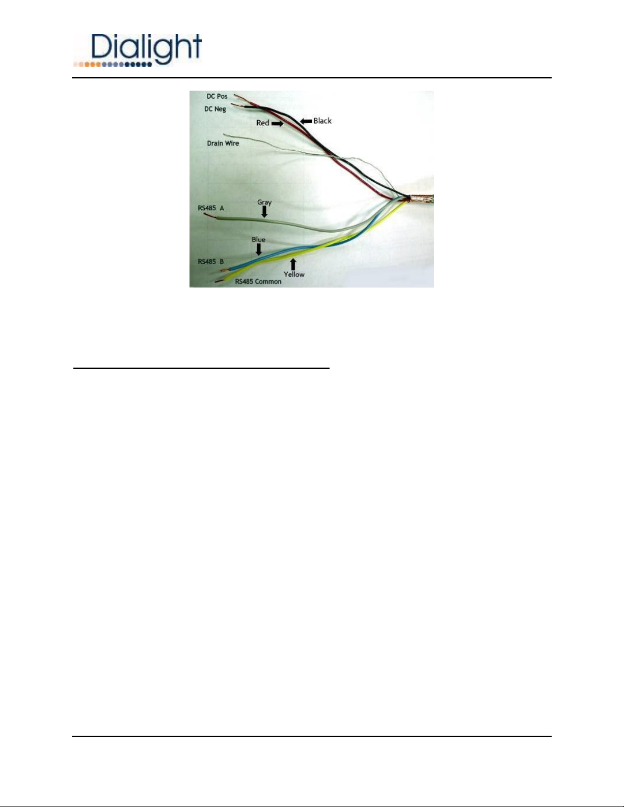
Section 13.0: Power Supply Cable Definition & DC Connections
The Flash Head cable is supplied factory installed into each of the modules that make
up the Flash Head.
Connect the Flash Head cables to the Power Supply Enclosure so that the electrical
connections can be tested on the ground. Each of three red cables should be passed through
a corresponding cable grip. All cables and cable grips are numerically labeled for easy match
up. The ends of each cable have been prepared for connections within the enclosure. The
triad of blue, yellow, and gray wires is for communication. The pair of black and red wires is
for DC power from the Power Supply Enclosure to the Flash Head. Do not alter the length of
these wires or attempt to cut back or modify the exposed braided shield. The picture below
shows the prepared cable end.
Level 1
Level 3
Level 4
Level 5
Level 6
Level 2

Document: 9100-127-2905-99
Revision B
Release Date: 1/23/2017
Dialight Corporation 1501 Route 34 South Farmingdale, NJ 07727
Tel: 732.919.3119 Fax: 732.751.5778 Web: www.dialight.com
Page 19 of 40
NOTE: The cable grip has been pre installed on to the cable. The nut must first be removed
after securing the cable grip to the enclosure.
Land the exposed braid underneath one of two large clamp washers (whichever one which
lines up with that cable grip position). Two cable braids can be landed side by side on the
clamp washers as shown below. Pull enough of the cable length through to reach all
connections before tightening down the washers.
FAILURE TO PROPERLYTIGHTEN DOWN CLAMP WASHERS WILL MAKE INTERNAL
COMPONENTS VULNERABLE TO SURGE OR LIGHTNING DAMAGE AND VOID THE SYSTEM
WARRANY
NOTE: If the Red and Black wires need to be cut and re stripped then ¾”of insulation
should be removed. The wires must be neatly twisted before inserting in to the terminal
blocks.
Document: 9100-127-2905-99
Revision B
Release Date: 1/23/2017
Dialight Corporation 1501 Route 34 South Farmingdale, NJ 07727
Tel: 732.919.3119 Fax: 732.751.5778 Web: www.dialight.com
Page 20 of 40
Steps for inserting the Red and Black wires:
The DC power wiring needs to be terminated on the DIN rail terminal blocks connected
to J2 of the Filter / Surge board as shown in Figure xx below. The DIN rail terminal blocks are
labeled appropriately for each module.
NOTE: Module #1 gets connected to pins 1 and 2 of J2 (left), Module #2 gets connected to
pins 3 and 4 of J2 (middle), & Module #3 gets connected to pins 5 and 6 (right).
NOTE: It is recommended that each Red and Black wire gets twisted on the exposed copper
before inserting into the terminal block.
Use a small flathead screwdriver to terminate by inserting the blade in to the slot and
easily lifting the screwdriver, then inserting the wire. The wire must go in easily and must not
be forced into the terminal bock.
If it is forced then the wire should be removed re-twisted and inserted again.
NOTE: Tug on these connections to ensure the wire ends were landed properly.
Drain wires from all three Module cables must be terminated on the grounding bus. This
connection is for lightning / surge protection and should be double checked like all other
wiring discussed above. Since the drain wire is a bare wire, extra attention should be placed
on routing these connections neatly.
Other manuals for L-856
2
This manual suits for next models
3
Table of contents
Other Dialight Lighting Equipment manuals

Dialight
Dialight DuroSite User manual

Dialight
Dialight Vigilant User manual

Dialight
Dialight HBXW3SSL304FT User manual

Dialight
Dialight Vigilant Bulkhead Guide

Dialight
Dialight L-856 Troubleshooting guide

Dialight
Dialight VIGILANT Series User manual

Dialight
Dialight SAFESITE LSD3C4M2P Manual

Dialight
Dialight HBXREF22 User manual

Dialight
Dialight SafeSite User manual

Dialight
Dialight Reliant User manual


