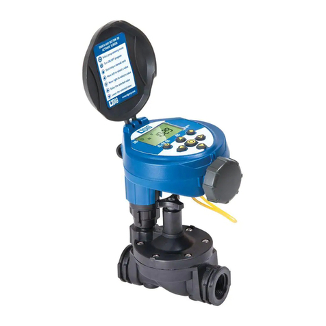
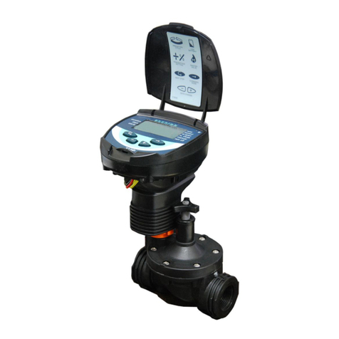
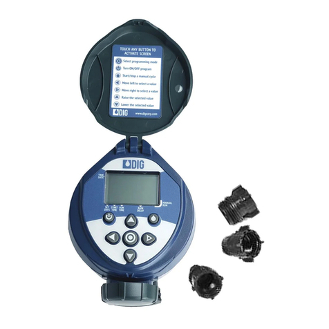
DIG GQ-AC4 User manual

GQ-AC4, GQ-AC6, GQ-AC8
Indoor Mounting AC Irrigation Controllers
INSTRUCTION MANUAL
Features
• Three (3) programs A B C to select
• Watering durations from 1 minute to up to 4 hours in 1-minute
increments
• Three (3) programs with four (4) start times per program with delay
options in weekly mode and one start time per day in cyclical mode
• Auxiliary X program in a weekly mode used for lights and ponds
through the use of a relay
• Custom programming with 7-day calendar or intervals of 1-31 days
in odd/even or every day rotation
• Operate four (4), six (6) or eight (8) stations with master valve or
pump start
• Five (5) buttons with a large dial and large integrated liquid crystal
display (LCD) for easy view and programming
• Off mode option on the dial allows the system to be shut off for an
unlimited time
• Includes testing feature of valve or
zone, making sure that the zone is
operating correctly
• Dedicated sensor terminal allows
operation with rain, freeze or moisture
sensors
• One 9-volt backup battery with battery
icon alert if battery is low and needs to
be replaced
• Reset button is available for a total reset
of the controller; in this option all programs
will be erased
• Full 3-year warranty

2
TABLE OF CONTENTS
1. Introduction …………………………………………………………… 3
2. About the GQ-AC controller …………………………………………… 3
3. Mounting the controller………………………………………………… 4
4. Connecting the valve wires to the controller …………………………… 5
5. Connecting a master valve or pump start relay ………………………… 5
6. Connecting a rain sensor ……………………………………………… 6
7. Connecting the backup battery ………………………………………… 7
8. Connecting the transformer wire to the controller ……………………… 8
9. Programing …………………………………………………………… 8
10. Setting current time, day of week and date……………………………… 10
11. Time format (switching between AM/PM and 24 hour)…………………… 10
12. Selecting watering frequency …………………………………… 11-12
13. Setting a start time …………………………………………………… 13
14. Programming water duration…………………………………………… 14
15. Setting budget ………………………………………………………… 15
16. Setting “Rain Off” (shutdown) ………………………………………… 16
17. Manual operation via the program ………………………………… 16-17
18. Mode X support program for pump, lighting and fountains ……………… 18
19. Valve testing ………………………………………………………… 19
20. OFF mode …………………………………………………………… 20
21. RUN mode …………………………………………………………… 20
22. Low battery warning…………………………………………………… 21
23. Trouble-shooting and repair …………………………………………… 22
24. Warranty ……………………………………………………………… 23
25. Technical assistance…………………………………………………… 24

3
1. INTRODUCTION
Thank you for purchasing one of DIG’s GQ-AC 4, 6 or 8 station-controllers. This manual describes
how to get the GQ-AC controller up and running quickly. After reading this manual and having
been familiarized with the basic functionality of the controller, the manual can be used as a
reference for less common tasks in the future. If you have any questions, please call our customer
service line at 1-800-322-9146.
2. ABOUT THE GQ-AC CONTROLLER
The new four, six and eight station GQ-AC controllers are the ultimate user-friendly
controllers for residential and light commercial applications. Easy to install and program, the
GQ-AC provides the user with a wide range of irrigation programs and features that meet
today’s irrigation needs.
The controller illustration shows the front with the programming buttons, dials and the
terminals.
1. Dial selector: used to select the desired programming mode includes clock setting mode
2. Switch button: move throughout the various display options to be used
3. Data increment button decreased: lowers the value of the selected parameter
(example, hours selected are changed from 06:00 to 05:00)
4. Data increment button increased: raises the value of the selected parameter
(example, hours selected are changed from 06:00 to 07:00)
5. Arrow button: used to select the parameter to be changed (hour, minute, etc.)
only a blinking parameter can be changed
6. Program button: moves between programs A, B, C and X in repeating order
7. GQ-AC terminal: use to connect the transformer
8. Terminal: to connect the valve stations and rain sensor

4
3. MOUNTING THE CONTROLLER
Before installing the controller, make sure you have a Phillips screwdriver, one 9-volt battery
18-gauge color-code, multi-strand, direct burial wire and WATERPROOF SPLICE CONNECTOR.
1. Select an indoor location near a 120 VAC outlet. The location should be protected from
moisture and sunlight.
2. Place the controller slightly below eye level, see example of mounting sketch. Mount the
controller to the wall with #6 or #8 screws (not included).
Note: If installing on drywall, install screw anchors (not included). (see figure 1 – 2)
3. Slide the controller down into position on the screw, then insert two screws on the bottom
corners. (see figure 3)
Note: If the controller is installed outdoors, use a water-resistant cabinet.
DO NOT PLUG THE TRANSFORMER INTO POWER SOURCE UNTIL THE CONTROLLER IS
MOUNTED AND ALL VALVES HAVE BEEN CONNECTED.
3 1/8” 3 1/8”
4 1/2”

5
4. CONNECTING THE VALVE WIRES TO THE CONTROLLER
1. Select and use suitable 16, 18 or
20-gauge direct burial, strand gauge
sprinkler wire between the valve
location and the controller. 18-gauge
direct burial, strand multi-color coded
wire is recommended.
2. Each valve connects to the controller
using two wires, hot wire (color-code)
and common wire (white). The common
wire (white) is shared with all valves.
At the valve, connect the common wire
to either solenoid wire of all valves using waterproof wire splice connectors. Connect
each color code wire to the remaining wire of each valve using waterproof wire splice
connections. (see figure 1)
3. Remove the cover from controller to access the terminal strip area. (see figure 1)
4. Connect the valves common wire to one of the four (4) “COM” common terminals
available. Connect each valve color-code wire to the appropriate station # on the controller
terminal. (see figure 1)
NOTE: Make sure the wires connections to the terminals are tight and firm.
WARNING: Do not connect more then one valve wire to each terminal.
5. CONNECTING A MASTER VALVE OR PUMP START RELAY
24 VAC master valves can be attached at the inlet to the irrigation system. The master valve
will automatically open with the first valves and will close automatically when the last valve
is closed. The master valve is shown on the controller display by the letter: M and on the
connections panel by the letters VM.
MASTER VALVE
a. If master valve is used, connect the common wire to one of the four (4) “COM”
terminals available and the valve color-coded wire to the VM terminal. (see figure 1)
PUMP
a. If pump is used, mount the controller a minimum of 15 feet away from a pump start
relay and the pump.
b. Connect either wire from the pump start relay to the controller terminal “VM” and
connect other wire to one of the four (4) “COM” common terminals available.
NOTE: To operate a pump, a pump start relay must be used. Do not connect controller
directly to pump start, it can damage the controller. Connecting the controller to a
pump is to be performed by a qualified electrician only.
Figure 1

6
6. CONNECTING A RAIN SENSOR
An interrupt type normally open rain sensor can be connected to the controller. The sensor
connects directly to the two controller sensor terminals “SNS”.
1. Connect either wire from the sensor to the two sensor terminals on the controller (see
figure below). Follow sensor manufacturer’s instructions for calibrating the sensor.
2. When the sensor is activated, a sensor icon appears on the display. In that mode it
prevents the valves from being opened.
NOTE: The regular mode on the screen for sensor is NC. Connection to the sensor
terminals is blocked by a piece of metal bridge. In order to install the sensor, the
bridge must be removed from the terminal board. In order to re-block the sensor, the
bridge should be re-installed. Should the bridge be lost, the sensor’s exit can be fused
with the aid of regular electric wire.

7
7. CONNECTING THE BACKUP BATTERY
• Remove the cover. (see # 1)
• Pull out the 9-volt battery clip wire found on the right side of the controller.
• Insert the 9-volt alkaline battery into the clip. (see # 2)
• Insert the battery into battery compartment and replace the cover. (see # 3-4)
The dial selector is on OFF and the screen display will show OF:F blinking and an AC icon
if the transformer is not plugged into the wall socket.
NOTE: The battery is intended for irrigation program memory backup only. During
electrical outages the program will not be erased, however, valves will not operate.
The controller can be programmed with the use of the battery.

8
8.
CONNECTING THE TRANSFORMER WIRE TO THE CONTROLLER
WARNING: Do not plug transformer into power source until the controller is mounted.
After connecting all valve wires and installing the battery, you are ready to connect the
transformer. Use only the supplied transformer, or a transformer with 110 VAC power input,
50 Hertz and 24 VAC output.
1. First, connect the transformer wire to the two terminals marked “24V”. (see figure below)
(Polarity does not matter).
2. Plug the transformer to 110 Volt electrical outlets.
Note: If power is
interrupted to the
controller when
irrigation is on, the
valve will close
automatically
and irrigation will
stop, although
the controller will
continue to operate
per the program.
9. PROGRAMMING
General Information
The GQ-AC controller is ready to program. Lift the cover and remove the plastic sheet that
protecting the LCD display. At this stage the user needs to program the controller.
Before programming the controller:
The GQ-AC controller has three irrigation programs, A, B, and C. In addition, it has an
additional support program, program X that can also be activated. The three programs (A,
B, and C) can be used to operate all the valves. In each program, days of watering can be
selected in which all the valves activated by one of the three programs. Start-time is set
only for the first valve on the system, with the irrigation duration being defined for each valve
separately. The valves are opened in sequence per their number as shown on the display
screen. When the first valve shuts down, the second valve opens up and so on. At any one
time only one valve operates. If the three programs are used (A + B + C) with irrigation times
which overlap, program A will open first and only after it shuts down, program B will open,
then program C opens last. Any of the valves can be operated by any of the three programs,
with differing durations under each program.

9
PROGRAMMING CONT.
The controller is programmed with the aid of a 10-mode dial selector and
5 buttons.
Dial selector: used to select the desired programming mode - includes clock
setting mode
Switch button: move throughout the various display options to be used
Data increment button decreased: lowers the value of the selected parameter
(example, hours selected are changed from 06:00 to 05:00)
Data increment button increased: raises the value of the selected parameter
(example, hours selected are changed from 06:00 to 07:00)
Arrow button: used to select the parameter to be changed (hour, minute, etc.)
only a blinking parameter can be changed
Program button: moves between programs A, B, C and X in repeating order

10
10. SETTING CURRENT TIME, DAY OF THE WEEK AND DATE
To enable the controller to operate the system at the correct times, the current
time and current day of the week must first be set. Steps below explain how to set
the day and time.
Turn the to TIME/DATE mode .
Press the and the hour digits will flash. Press the or to set the current
hour (note: use of AM and PM designations). Press the , minutes digit flash, set
the current minute using or .
Press the , the year, month date appear with the YEAR blinking. Press the
or and set the year. Press the , the month appears with the MONTH digit
blinking. Press the or and set the month. Repeat the steps to and the date
and day of the week. To repeat or review any step, press button.
11. TIME FORMAT (SWITCHING BETWEEN AM/PM
AND 24 HOUR)
The default time format is AM/PM. There is also a 24-hour time format. After the
date and time have been set press several times until appears. Press ,
hour digit will blink. Press the and simultaneously. The clock reading switches
from AM/PM to a 24-hour time display or vice versa.

11
12. SELECTING WATERING FREQUENCY
This controller has three operation methods of activating programs A, B, or C. This
setting determines how often the controller will operate with each program. After
selecting the program, choose either program according to the days of the week, a
cyclical irrigation cycle, which waters once every certain number of days (i.e. once
every 3 days is a cyclical cycle) and even or odd days.
To see the option in each program, press and the following modes will appear:
OFF, Weekly mode , next, cyclic mode with 1-30 days, and last, ODD or
EVEN modes .
Weekly Program Example: Program the controller to operate on Wednesday,
Thursday, Friday an Saturday.
Turn the to WEEKLY/CYCLIC mode.
If not in a weekly mode , press and select the weekly mode, arrow under
M (Monday) and appears. Press to skip Monday and Tuesday, the arrow
will disappear and will reappear flashing under Wednesday. To select Wednesday,
press and the arrow remain fixed.
Press again, the arrow skips to Th (Thursday) and remain fixed. Press
to skip F (Friday), the arrow will disappear and will reappear flashing under Sa
(Saturday). Press , the arrow under Sa (Saturday) remains fixed. Repeat the
same steps to select Su (Sunday) and move to next step START TIME.

12
Cyclic Program Example: Program the controller to operate every 5 days
Turn the to WEEKLY/CYCLIC mode.
Press and select cyclic irrigation appears with EVERY 1 DAY. To select every
1 days, press and 1 is blinking. Press and change the blinking 1 to EVERY 5
DAYS. Repeat the same steps to change the 5 days setting or move to next step
START TIME.
Weekly Program Example: Program the controller to operate on EVEN days
Turn the to WEEKLY/CYCLIC mode.
Press to select EVEN mode, the appears under EVEN and the day of the
week to water arrow appears under every day. Select the day on which there
will be no irrigation. Press , and the day of the week to water arrow is
blinking under M (Monday). Press to select the irrigation day. Press , and
the day of the week to water arrow is blinking under Tu (Tuesday). Press to
skip Tu (Tuesday). The arrow will disappear and will reappear flashing under W
(Wednesday). Repeat the same steps to cancel any irrigation day of the week. The
same method is use when selecting ODD days. To deactivate the program, press
until OFF appears. Move to next step START TIME.
(Change the
1-day to 5)

13
13. SETTING A START TIME
In a Weekly mode setting, it is possible to set up to 4 start times per day for
each program (A, B, C) and in Cyclic mode setting only one start time per day is
available. At each start-up time the first valve selected for the program will be
activated and thereafter the other valves will be opened in a sequence.
Weekly mode:
Turn the to START TIME mode.
START I will appear on the left side of the LCD display with the weekly activation
mode and the word OFF or the last start time entered. Press and OFF is
blinking. Press or to set the desired start time hour (7), please note and
select AM or PM. Press the minute is blinking, press or to set the
desired start time minute (30). Press for additional start time and repeat the steps
if needed for programming START 2, 3 and 4. To cancel one of the start times
press , the hour digit blinking, press or until the word OFF appears. (OFF
appears after 11:00 PM)
Cyclic Mode:
This mode has only one start time and a number of days to delay the valve start
time. The number of day(s) to delay option will appear on the display to the right of
the start time above the word “days”.
Turn the to START TIME mode.
START I will appear on the left side of the LCD display with the cyclic activation
mode and the word OFF or the last start time entered. Press and OFF is

14
blinking. Press or to set the desired start time hour (12), please note and
select AM or PM. Press the minute is blinking, press or to set the desired
start time minute (30).
Press and 1 day is
blinking. Press the or
to select the number of
days to delay the start
time.
14. PROGRAMMING WATERING DURATION
This setting determines the length of time that each valve will remain open. Up to
4 hours of watering can be selected for each valve on each program in 1-minute
increments.
Turn the to DURATION mode.
The screen with the program used A, B or C, the time is set to 0:00, the duration
icon appears and the icon above the valve # appears blinking. Press the
hour digit is blinking. Press or and set the desired duration time in hour (Max
of 3:59 can be added).
Press the minute is
blinking, press or
and set the desired
time in minutes (30).
Press and skip to
next valve. Press the
hour digit is blinking.
Repeat the same steps
for each active valve.

15
15. SETTING BUDGET
The amount of irrigation water applied during seasonally dry or wet periods
changes throughout the year. Instead of changing the duration for each program,
the Budget feature can be utilized to reflect the seasonal changes. Budgeting
is programmed once to increase or decrease the irrigation on a monthly basis
for an entire year. Budget adjustments can range from 10% – 190% in 10%
increments for each program. The controller will automatically adjust the previously
programmed durations according to the specified budget.
Turn the to WATER BUDGET mode.
Press until the program used appears. 100% will appear with the program
selected and above the active valves. Press and the 100% digit in the screen
are blinking. Press or and set the desired value with of higher or lower
percentage of irrigation duration. Press once will add 10% and pressing once
will reduce it by 10%. Press if required, and change the program mode from A
to B or C. Repeat the steps for each active program.
Note: With adding or subtracting a percent from the duration will have a
maximum of 4 hours and a minimum of 1 minute.

16
16. SETTING “RAIN OFF” (SHUTDOWN)
This option is used to temporarily suspend the controller program A, B or C or all of
them. The irrigation schedule remains stored in the controller memory, but is not
implemented until the suspension is canceled. The suspension option can be from
1 day up to 240 days. When the suspension expires, the controller return to the
original program.
Turn the to RAIN OFF screen mode.
Press until the program used appears with the selected program A, B or C,
the above the active valves, the icon and 00. Press and the 00 DAYS is
blinking. Press or and set the desired number of irrigation days suspension
from 0-240 days. Repeat the steps for each active program if needed.
17. MANUAL OPERATION VIA THE PROGRAM
This option is used to operate a valve manually using one of three options:
Option 1: Open all the valves via the MANUAL using one of the programs.
Option 2: Open one valve via the MANUAL.
Option 3: Open all the valves via the MANUAL using the three programs.
Note: Manual operation will terminate any program that is active in the same
time, all programs will return to normal operation after manual irrigation is
complete.

17
Option 1: Open all the valves via the MANUAL using one of the programs.
Turn the to MANUAL mode.
Program A appears first with above the valves operates by the program with the
word OFF and the icon. To open press , the word ON will appear and a will
appear above the first valve, a few second later a will appear if the master valve
is active. Valve one will open
and next valve will follow one
after the other.
Option 2: Open one valve via the MANUAL.
Turn the to MANUAL mode.
Program A appears first with above the valves operates by the program with
the word OFF and the icon. To open a specific valve in the program, first press
, the above first valve is blinking and the program duration for the valve will
appear. To open valve # 1, press , the valve will open and a above the valve
number, the word ON and
the valve # appears a second
later. To skip valve # 1 and
open the second valve press
and press to open
valve # 2. Repeat the steps
for other valves. If master
valve is active, it will open
and will appears above
the master valve.

18
Option 3: Manual operation of all valves via the 3 programs.
Turn the to MANUAL mode.
Program A appears first with above the valves operates by the program with
the word OFF and the icon. To select A, B, and C program, press until ABC
program appears with word STOP, with above the valves and the . To open
the valves with the programmed time in A, B a C press the or .
All valves that have irrigation duration in program A, B and C will start open one
after the other. The open valve icon will appear with the word RUN and if master
valve is active the icon will also appear.
18. MODE X SUPPORT PROGRAM FOR PUMP, LIGHTING
AND FOUNTAINS
Program X allows the user to activate a fountain, garden lighting and others.
Program X can be activated only in the WEEKLY/ CYCLIC mode. Using this program,
master valve, rain sensor, rain off and budget are not used and will not influence
this program, but can be operating by the other programs. Use of this program will
require a relay interface kit with 24 VAC and max of 50 mA.
NOTE: Program X operated the last valve of the 4, 6 and 8 station controllers.
NOTE: If the relay is connected to any circuit higher than 24-volts, it must
be located in its own high voltage junction box in accordance with local
electrical code.

19
Turn the to WEEKLY/CYCLIC mode.
Press the button and program A appears first with above the active valves
with the word OFF and the . To select program X, press until program X
appears with word OFF. To activate program X, use the same method to activate
any other program. First select the days of the week to operate, then the start time,
then the duration time.
Note: X program can be programmed only when the last valve on has not been
used with any of the programs.
19. VALVE TESTING
This feature allows the user to physically test any valve at any time for malfunction
of open or short circuit or for testing the system.
Turn the to TEST mode.
A number that represents the number of valves appears at the center to the right
of the screen (with 4 for four station, 6 for six station and 8 for eight station). The
controller version number appears on the right side, as all the above each valve,
identifying the controller number of valves.
Press and the first valve will blink. Press and the master valve will open
immediately and the irrigation start with valve # 1 open. To stop valve number 1
and move to the next valve, press again and valve # 2 will open. If there is no
irrigation you may have a malfunction in this valve and it should be investigated. If
the symbol flashes above a valve #, there is a short in the valve or in the wires
leading to it. The valve should be disconnected and the short repaired. To stop the
test, press and the valve will close.

20
20. OFF MODE OPTION
The OFF mode option allows for the immediate shutdown of all the programs for an
unlimited time.
Turn the to OFF mode.
The word OFF will appear on
the screen blinking. Press
, OFF will stop flashing
and the active program will
discontinue immediately. To
reactivate the program turn
the dial from the OFF mode
to any other mode, the
programs will resume from
the start-up of the next in
line program, according to
the hour and the day.
21. RUN MODE OPTION
The RUN mode presents data as to the current mode. In this screen the user can
see all controller activity. In this mode there are no programing possibilities.
• Open valve will blink on the display, with a countdown showing irrigation time
remaining.
• If one of the programs is in OFF, the symbol will appear.
• If budget is used the icon %will appear.
• If backup battery is low, battery warning will appear and we recommend
changing the battery. The battery serves only as backup for the program. In a
power-failure, and when the battery is low, the program is not lost but retained
in the controller for 20 years. When the electricity returns, the controller screen
will start to blink and the programs will return to normal.
• If AC power is not connected to the controller, the icon AC will appear,
indicating the controller is not plugged in or connected to the transformer,
though the screen will display all the functions.
Note: If no AC power is available the valve will close and irrigation will stop
although the controller will continue the program.
This manual suits for next models
2
Table of contents
Other DIG Controllers manuals
Popular Controllers manuals by other brands

Omron
Omron EP-3 - datasheet
Johnson Controls
Johnson Controls TEC3620 Series Installation & operation manual
Heatit Controls
Heatit Controls Z-PUSH WALL CONTROLLER Installer manual
Oceanled
Oceanled WiFi DMX TOUCH Installation & operation manual

Craftmade
Craftmade WUCI-1000 Installation and operating instructions
Thorlux
Thorlux SmartTouch installation instructions
