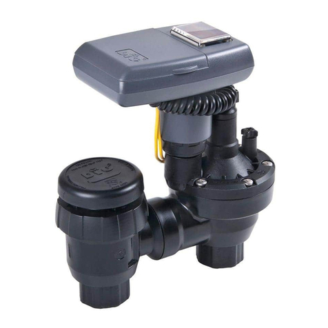
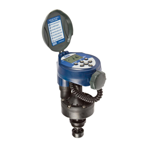
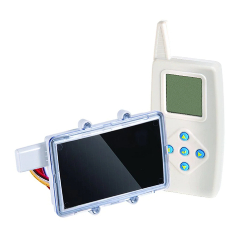
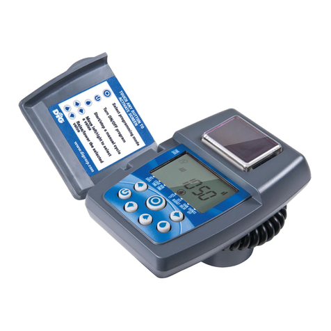
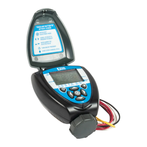
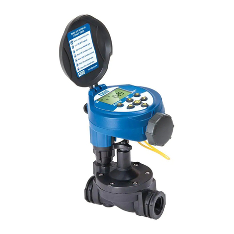
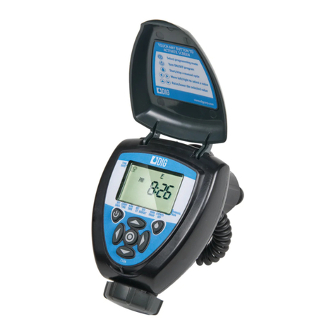
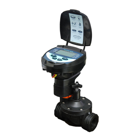
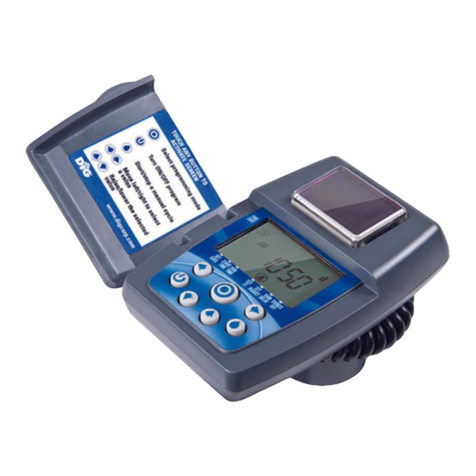
DIG 510.P Series User manual

23
• Open window:AM or PM
• Close window:AM or PM
DIMENSIONS
• Height:6" (15 cm)
• Width:4" (10 cm)
• Depth:2" (5 cm)
BATTERY INSTALLATION
Rotate the battery compartment
cover handle to the 11 o’clock
position to remove the cover
(see drawing). Insert two
9-volt alkaline batteries.All
controller display elements
will briefly appear on the
display, followed by the
blinking time“12” – the
controller is now ready to be
programmed.
IMPORTANT: To replace the battery compartment cover, insert
it with the handle in the“11”o’clock position to avoid
possible cover guide pin breakage.
ASSEMBLY AND INSTALLATION
OF CONTROLLER UNITS
MODELS 510.XXXP AND 510.075P
If the mounting plate [2] is
attached to the controller,
remove it.
1. Insert the mounting coupling [1]
into the mounting plate, aligning
the words“top”, which are
stamped on both the coupling,
and the plate.
2.Press the mounting plate,with
the mounting coupling inserted,
against the irrigation controller
back.
WALL ORVALVE MOUNTING
The controller mounting plate [2] can be mounted on a wall
using two screws,in which case mounting coupling [1] is not
used.The distance between the controller and the solenoid is
limited by the length of its connecting cable. To mount
controller on a valve, use plate #1.
ASSEMBLY & INSTALLATION OF
MODEL 510.075-100 AND 510.000P
1. Shut the main irrigation system
valve.
2. Before installing the hydraulic valve
[5] in the irrigation system, remove
the solenoid [1] from the valve with
a 90° counter-clockwise turn.Be
careful not to lose the seal (O-Ring
#2) [3].
3. Install the hydraulic valve in the
irrigation system, paying attention to
the correct water flow direction, as
indicated by the arrow [4].
4. After installing the hydraulic valve [5],assemble the solenoid
with a 90° clockwise turn.Be sure to place the seal (O-Ring #1)
[3] in its proper location.
MANUAL-MECHANICAL OPERATION
The valve can be opened and closed
independent of controller operation.
Manual operation is useful when
immediate irrigation is required, without
the delay of controller programming.
The 3-position valve handle [A] is located on the solenoid Manual
valve,and functions as follows:Open [1],Automatic Operation
[AUTO],Closed [2].
IMPORTANT: For automatic operation,the valve handle must
be in the middle [AUTO] position.
PARTS IDENTIFICATION
1. Top Cover
2. Controller Display
3. Bottom Cover
4. Battery Compartment Cover
5. Solenoid
6. Valve Handle
7. Bayonet
8. Manual Flow Control
9. HydraulicValve
INSTALLING THE IRRIGATION CONTROLLER
Your controller can be installed in line directly to PVC pipe fittings,
(inlet female pipe thread,outlet female pipe thread)
NOTE: Wrap all fittings with teflon tape.Do not use thread
paste on valve as this will damage the valve and void your
warranty.
NOTE: The controller can be mounted in any position.We
recommend a short test cycle before attaching your lines to
the outlet side.
IMPORTANT: Make sure flow direction arrow is pointed away
from water source.Never use the controller unit as a handle
for tightening the valve to the pipe.
CONNECTING A RAIN SENSOR
An interrupt type rain sensor can be connected to the controller.
The sensor connects directly to the controller wire connection(s).
Connect either wire from sensor to the two sensor wires on the
controller.
PROGRAMMING THE CONTROLLER
DIG controllers are programmed with the aid of four buttons:
Programming step selector – used to select the desired
programming mode (includes clock setting mode)
Next step button – used to
select the parameter to be
changed (hour,minute, etc.).Only
a blinking parameter can be
changed.
Data increment button
(Increase) – Raises the value of
the selected parameter (e.g.,
when time selected from 06:00 to
07:00).
Data increment button
(Decrease) – Lowers the value of
the selected parameter (e.g.,
when time selected from 06:00 to
05:00).
PROGRAMMING CURRENT TIME AND DAY OF THE WEEK
Press a number of times until
icon appears. Press .The
hour digit will flash.Use the or
buttons,to set the current time
(note:use of AM and PM).A further
press of will make the minutes
digit flash.Use the or to set
the current time.Press .A flashing arrow will appear in the
upper portion of the display. Use the or to set the current
day. Press to move to the next step.
If the last data entered stops flashing, press the again to
resume programming.
PROGRAMMING WATERING TIME:
HOURS,MINUTES AND SECONDS
Press until icon appears.Use
and or to set the desired
watering time.
Press to move to the next step.
PROGRAMMING WATERING SCHEDULE
Press until icon appears.At this stage you can select one
of two program options:
A)Watering schedule according to the days of the week.
B) Cyclical schedule watering – once,minutes, hours and days.
A.Watering schedule according to the days of the week.
Press , a flashing arrow appears
opposite the days of the week.Use
the or buttons for the desired
day.A non-flashing arrow shows the
Watering Day selected.In this way,
move along the days of the week
and set any day of the week
required.
To cancel a Watering Schedule: Press when the arrow is
flashing beside that day.
B.Cyclical, , minutes,
hours and days watering
For operating the watering schedule
cyclically or press the
a number of times (pass over every
day of the week) until the word
appears. for
single watering if required (make sure that no arrow shows on the
day of the week).
Cyclical schedule watering – press and the word will
flash.Use or to set the desired watering cycle,from
1 minute up to 45 minutes,from 1 hour up to 23 hours and from
1 day up to 30 days.When you leave the icon on,
program will operate one time only,and the controller needs to be
programmed again.
Press to move to the next step.
PROGRAMMING A WEEKLY START TIME
(For watering according to the days
of the week.) Programming the
controller by day of the week allows
4 start times per day. Press for
start no.1.The word will
appear (or the last start time
entered).Press the word flashes.Use the or to
set the desired start time (noteAM and PM). Press to program
start no.2 and repeat the same steps for starts no.3 and 4.To
cancel one of the start times,press .The hour digit flashes.
Use the or to display .
PROGRAMMING A CYCLICAL OR START TIME WITH
START TIME DELAY
Programming a start time with these
programs will allow the use of an
additional function defined as
“number of days”.You will be able
to set the first start time today (day
0),tomorrow (day 1) or any number
of days required (up to 30 days).Press .Use or to set
the desired start time,and day. (Only one start time in this mode).
MANUAL OPERATION
Press the .The icon appears.
Use and to open or close the
valves.
• In manual operation, the valve
will close automatically after
the programmed watering time.
INTRODUCTION
THANKYOU for purchasing a DIG Controller.
Please take the time to read through the enclosed instructions and
follow them step by step. If you have any questions,please call
our customer service line 1-800-344-6641.
CONTROLLER MAIN FEATURES
• Operates on two 9-volt alkaline batteries
• Weekly or Cyclical program
• Up to four start times per day in weekly mode
• Station run time from 1 second to 12 hours in 1 second
increments
• Watering Schedule 7-day
weekly program or cyclical
from once a day to once
every minute, hour, and day
• Simple,four button
programming
• Optional manual operation
• Completely waterproof
• Can be mounted on valve or
on the wall
• Up to 30 days rain delay
SPECIFICATIONS
OPERATING SPECIFICATIONS
• Station run time: In 1-second increments up to 24 hours
• Watering Schedule:In 1-minute increments up to 5 minutes
In 5-minute increments up to 15 minutes
In 15-minute increments up to 45 minutes
In 1-hour increments up to 23 hours
In 1-day increments up to 30 days
7 days calendar
• Start time in irrigation mode: up to 4 start times per day
• Start time in propagation mode: one start time every minute
• Sensor:on and off
• Irrigation window allows for propagation at a defined part of the
day
OWNERS MANUAL
INSTALLATION INSTRUCTIONS
510.XXXP BATTERY OPERATED
PROPAGATION AND IRRIGATION
CONTROLLER
BAT
1-800-344-2281

”RAIN OFF”(SHUTDOWN)
Press .The sprinkler icon
appears.Press and icon
will appear.The controller is shut
down. Press to return to the
original programming.(The icon
will disappear.)
The shutdown mode causes the
valve to be suspended.The
programming,however,is
preserved.
SENSOR OPERATION
1.Press until appears next
to SENSOR.
2.Press to activate the sensor
in the irrigation program
selected.
*With the sensor circuit closed (i.e.,
the sensor detects the existence
of a defined program lockout
condition) the symbol blinks
on the display. In this situation,
irrigation will not take place
through the valve.
3.Press to disable the sensor.
The word“OFF” appears on the
display.
IRRIGATION WINDOW IN THE CYCLICAL PROGRAM MODE
The irrigation window is an advanced feature which enables
cyclical irrigation program operations (see Section B) to take place
only during a defined part of the day (window).The irrigation
window is defined as a part of a day (up to 23 hours), in the
cyclical irrigation mode only.
This function is useful when irrigation is only required during the
hot hours of the day. For example,open window 9 am,closed
window 4 pm.
Make sure that appears on
the display
1.Press until appears on
the display next toW.OPEN, with
the word OFF or last OPEN
WINDOW time setting displayed.
2.Press .The word OFF blinks on the display.
3.Press and to set the desired OPEN WINDOW time (pay
attention to the AM/PM designation).
4.Press until appears on
the display next toW.CLOSE, with
the 12 am or the last close
window time setting displayed.
5.Press .The 12 am blinks on
the display.
6.Press and to set the desired CLOSEWINDOW time
(pay attention to the AM/PM designation).
To disable the irrigation window function
1.Press until appears
next to OPENWINDOW, with the
last OPENWINDOW time setting
displayed.
2.Press .The irrigation window
open time blinks on the display.
3.Press until OFF appears next to .
VALVE IN OPERATION
A icon will appear. If the
flashes,the valve has not
opened,the possibilities are:
•Valve is in“short mode”.The
icon will flash once every
1/2 second (120 times every minute).
BLINKING LOW BATTERY WARNING
A blinking battery icon
appears on the display
when the batteries are
weak.In this state,a
limited amount of energy
still remains in the
batteries for valve
operation, and they should
be promptly replaced.
Press any button after
replacing the batteries to resume irrigation controller activity.
Program data will be retained for approximately 20 seconds
during battery changing.
CONSTANT LOW BATTERY WARNING
When weakened batteries
are not replaced in a timely
manner,the battery icon
appears constantly.All
other display elements
disappear and all valves
are closed.
Replace batteries promptly,
then press any button to
resume irrigation controller
activity.
Program data will be retained for approximately 20 seconds
during battery changing.
NO PROGRAM
During“manual” irrigation
system operation via the
irrigation controller,
“no prog”appears on the
display, meaning that no
irrigation period has been
set for the valve.In this
case,the irrigation
controller“does not know”when to close the valve.
In this situation valve opening is disabled.
MAINTENANCE AND TROUBLESHOOTING
PROBLEM: Valve does not open
CAUSE:One of the following not entered:Watering time,
watering days, start time
SOLUTION:Check and program as required
CAUSE:Selector on “RAIN OFF”position
SOLUTION:Cancal RAIN OFF
CAUSE:Valve or connection faulty
SOLUTION:Check the valve or replace it
PROBLEM: Sensor icon constantly flashes on display and valve
does not open
CAUSE:Sensor is shorted
SOLUTION:Replace sensor or repair sensor connection
PROBLEM: Valve does not close,despite click heard during
activation
CAUSE:Dirt or stones in the valve.
SOLUTION:Clean the valve
CAUSE:Valve was opened manually
SOLUTION:Move the handle to automatic position
CAUSE:Valve faulty (torn diaphragm)
SOLUTION:Replace valve or part
CAUSE:5mm seal (O-ring) is missing between the valve and
the valve coupling
SOLUTION:Install a new seal (O-ring)
PROBLEM: Display“disappears”
CAUSE:Batteries are weak
SOLUTION:Check the batteries
PROBLEM: Water leak from solenoid-valve adapter
CAUSE:O-ring is missing
SOLUTION:See assembly and installation
DIG CORPORATION 3 YEAR WARRANTY
DIG CORPORATION warrants these products to be free from defects in material and
workmanship for a period of three years from date of purchase.This warranty does
not cover damage resulting from accident, misuse,neglect, modification,improper
installation or subjection to line pressure in excess of 150 lbs. per square inch.This
warranty shall extend only to the original purchaser of the product for use by the
purchaser.This warranty shall not cover batteries or any malfunction of the product
due to battery failure.The obligation of DIG CORPORATION under this warranty is
limited to repairing or replacing at its factory this product which shall be returned to
the factory within one year after the original purchase and which on examination is
found to contain defects in material and workmanship.
DIG CORPORATION SHALL IN NO EVENT BE LIABLE FORANY INCIDENTAL OR
CONSEQUENTIAL DAMAGES OFANY KIND; THE SOLE OBLIGATION OF DIG BEING
LIMITEDTO REPAIR OR REPLACEMENT OF DEFECTIVE PRODUCTS.SOME STATES DO
NOTALLOW THE EXCLUSION OR LIMITATION OF INCIDENTAL OR CONSEQUENTIAL
DAMAGES,SO THEABOVE LIMITATION OR EXCLUSION MAY NOTAPPLY TOYOU.
Unattended use for prolonged periods without inspection to verify proper operation is
beyond the intended use of this product,and any damage resulting from such use
shall not be the responsibility of DIG CORPORATION.There are no warranties which
extend beyond the description on the face hereof.In the case of purchase of the
product for use other than,for irrigation purposes,DIG CORPORATION hereby
disclaims any implied warranties including any warranties of merchantability and
fitness for a particular purpose.In the case of the purchase of the product for
personal,family or household purposes, DIG CORPORATION disclaims any such
warranties to the extent permitted by law.To the extent that any such disclaimer or
implied warranties shall be ineffectual,then any implied warranties shall be limited in
duration to a period of one year from the date of the original purchase for use by the
purchaser. Some states do not allow limitation on how long an implied warranty lasts,
so the above limitation may not apply to you.
In order to obtain performance under this warranty,the unit must be returned to the
factory, along with proof of purchase indicating original date of purchase,shipping
prepaid,addressed as follows:
DIG CORPORATION,130 Bosstick Blvd., San Marcos,CA 92069. Repaired or replaced
units will be shipped prepaid to the name and address supplied with the unit returned
under warranty.Allow four weeks for repairs and shipping time. Repair of damaged
units not otherwise within warranty may be refused or done at a reasonable cost or
charge at the option of DIG CORPORATION.
This warranty gives you specific legal rights,and you may also have other rights
which vary from state to state.
789
TO ORDER PARTS:
1-800-322-9146 FAX: 760-727-0282
130 Bosstick Blvd.
San Marcos,CA 92069 E
www.digcorp.com/asdig
e-mail:[email protected]
© 1999 DIG CORP 26-034
This manual suits for next models
3
Other DIG Controllers manuals
DIG
DIG 5004-I Four Station User manual
DIG
DIG LEIT-2ET User manual
DIG
DIG 7001 User manual
DIG
DIG LEIT-2 User manual
DIG
DIG Irrigation-Mart 710 Series User manual
DIG
DIG ECO1 ILV-075 User manual
DIG
DIG LEIT1-000 User manual
DIG
DIG 400A Series User manual
DIG
DIG LEIT 4000 Series User manual
DIG
DIG 710AP Series User manual
Popular Controllers manuals by other brands
Omron
Omron EP-3 - datasheet
Johnson Controls
Johnson Controls TEC3620 Series Installation & operation manual
Heatit Controls
Heatit Controls Z-PUSH WALL CONTROLLER Installer manual
Oceanled
Oceanled WiFi DMX TOUCH Installation & operation manual

Craftmade
Craftmade WUCI-1000 Installation and operating instructions
Thorlux
Thorlux SmartTouch installation instructions
