Installation of Switch Panel
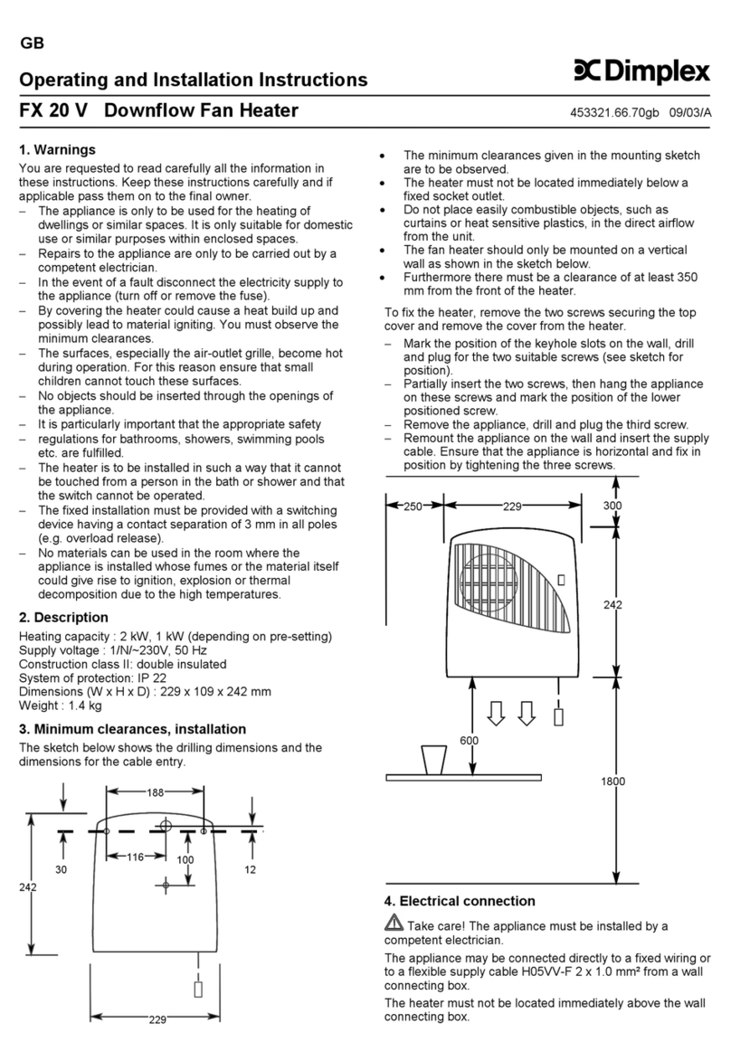
WARNING: The Switch Panel should not be installed in a toilet or
washroom.
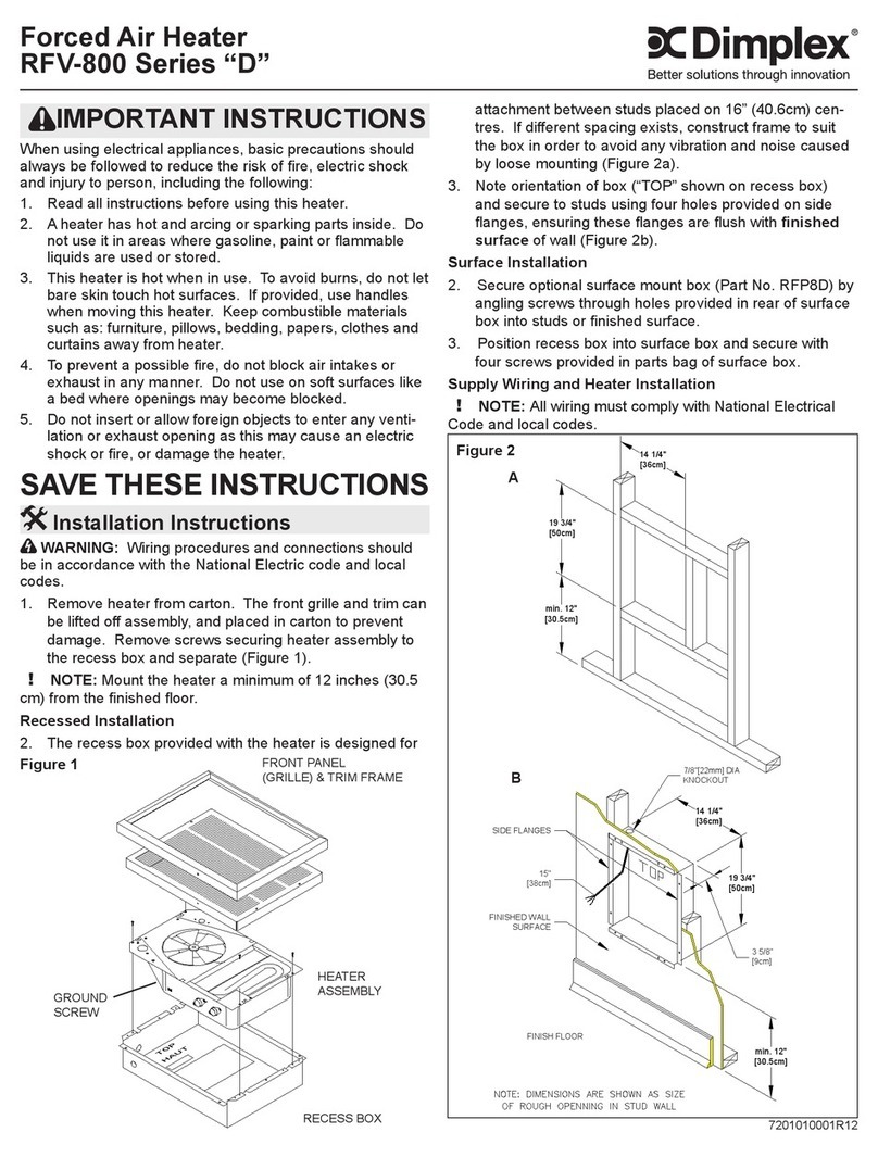
The backing box (standard B.S. double gang as shown in Fig. 5) should
be rebated into a suitable wall. The box should be fitted so that the switch
panel will be flush with the wall. Suitable wall conduit should be used where
applicable to carry the cable between the heater and the switch panel.
Installation of Heater
The Installation of this product must only be carried out by a prescribed
competent person in accordance with Building Regulations and the current
IEE Wiring Regulations for electrical equipment.
This heater can either be installed into a suspended or plasterboard ceiling.
First it is necessary to ensure that 200mm of sufficient space exists above
the ceiling for the Installation of this product (see Fig. 1 and Fig. 7).
This product is designed to be suspended by threaded rod or wires/chains.
Always ensure this unit is adequately supported when installed.
Mounting of Heater
Installation in a plasterboard (or similar) Ceiling
Ahole (610x610mm) as indicated in Fig. 1 and Fig. 6 must be cut into the ceiling.
It may be necessary to fix an internal supporting frame around the newly cut
aperture in a plasterboard ceiling.
To mount the unit into the ceiling void, use lengths of threaded bar or hooks
(not supplied) screwed into the M8 threaded inserts located in the top side
of the heater (see Fig. 1 for dimensions). Adjust the height of the heater so
the air inlet/outlet panel is positioned inside the grille frame and no more than
70mm above the installed height of the egg crate grille which allows access
for future maintenance. The unit should also be positioned inside the grille
opening to achieve optimum air-flow
effect, as shown in Fig. 8.
Installation in a Bulk Head
(over doorway)
A hole (576x265mm) as indicated in
Fig.7,must becut intotheceilingpart
of the bulk head. Drop rods should
be used to mount the appliance in
such a position, as to have the base
flush with the ceiling. An access
panel should also be provided on the
front of the bulkhead. This provides
access to the top of the appliance
and the access plate for wiring the
appliance.
Installation in a Suspended Ceiling
A standard 600 x 600mm ceiling tile needs to be removed as close to
the final position of the product as possible.
There are four options for mounting the appliance in a suspended ceiling:
1. Use suitable length M8 threaded bar and screw into the threaded inserts
provided on the top of the heater - see Fig. 1 for dimensions.
2. Bendup the‘Wire Hooks’as shown inFig. 9 and usesuitable suspended
ceilingwireto suspend theheater. (Note the applianceshould bemounted
as to prevent swaying of the product during operation).
3. Without Egg Crate Grill: Use the rail brackets provided. Bend the rail
brackets as shown in Fig. 10. The appliance should be placed directly
onto the suspended ceiling structure in the desired location. Using the
screws provided screw the rail brackets onto the heater (Top Holes -
see Fig. 9) so that it grips the suspended frame (see Fig. 10) Close the
remaining space around the heater with a cut ceiling tile.
4. With Egg Crate Grill: Use the rail brackets and ceiling tile provided.
Pick a location to mount the heater. Remove the existing ceiling tile
and replace with metal tile supplied. The appliance should be placed
directly onto the metal ceiling tile. Using the screws provided screw the
rail brackets onto the heater (Bottom Holes - see Fig. 9) so that it grips
the suspended frame (see Fig. 10).
Note: Please ensure that the ceiling structure can withstand the weight of
the appliance.
Operation of Switch Panel
Switch on electrical supply (MAINS IN) to the Switch Panel.
Switching the switch marked ‘I’ (see ‘1’ in Fig. 5) energises the fan and
switches on the electrical supply to the heater.
The heat selection switches allow heat settings to be chosen as shown
below:
Settings - I Fan Only
I +
1/2Heat
I +
Full Heat
The desired setting can be obtained through switch selection.
Fig. 6
4

