manuals.online logo
Brands
  1. Home
  2. •
  3. Brands
  4. •
  5. Dimplex
  6. •
  7. Heater
  8. •
  9. Dimplex FXPH1/42/750 User manual

Dimplex FXPH1/42/750 User manual

246
146
246
9.5mm dia. holes
9.5mm dia. holes
FXPH 2 Range
FXPH 1 Range
'A'
'B'
centres
143
centres
197
centres
95
182
143
146
'A'
centres
'B' 182
Tapped 20mm
Tapped 20mm
THESE INSTRUCTIONS SHOULD BE READ CAREFULLY AND RETAINED FOR FUTURE REFERENCE.
Dimensions
(millimetres)
Model(s)Specification
Watts Volts ‘A’ ‘B’ Weight Temp
FXPH1/42/750 750 240V 1067mm 870mm 14.7kg T2
FXPH1/42/750/110 750 110V 1067mm 870mm 14.7kg T2
FXPH1/60/1000 1000 240V 1524mm 1327mm 16.4kg T2
FXPH2/42/1500 1500 240V 1067mm 870mm 20.3kg T2
FXPH2/42/1500/110 1500 110V 1067mm 870mm 20.3kg T2
FXPH2/60/2000 2000 240V 1524mm 1327mm 23.6kg T2
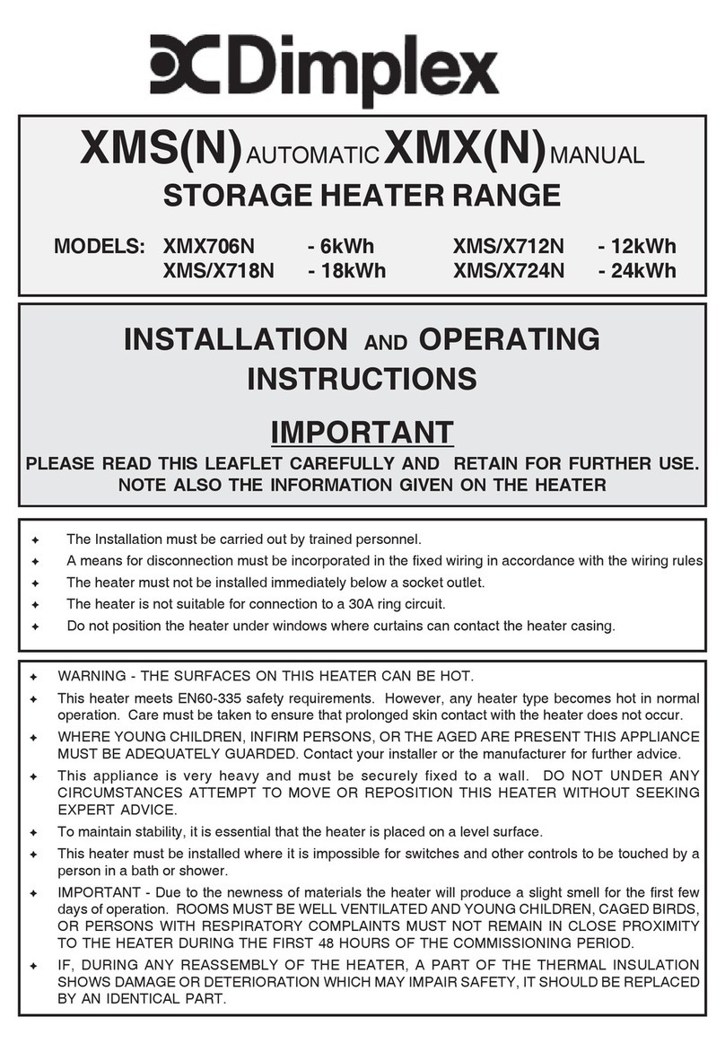
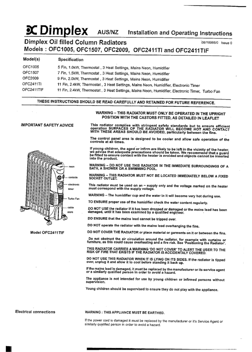
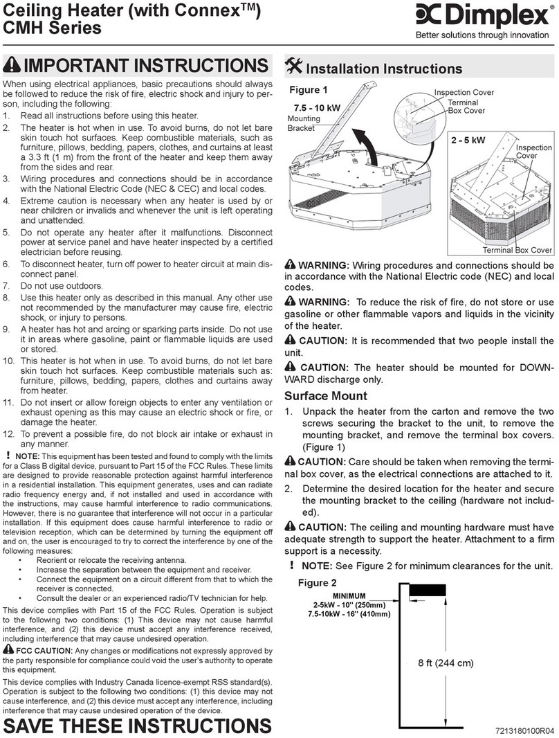
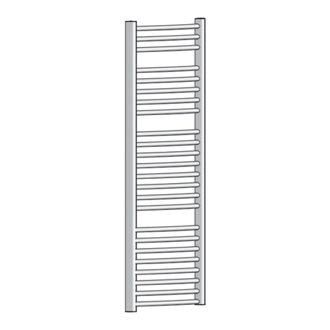
FXPH Flameproof Heaters
Models : FXPH1/42/750, FXPH1/42/750/110, FXPH1/60/1000 - Single Element
FXPH2/42/1500, FXPH2/42/1500/110 & FXPH2/60/2000 - Double Elements
Installation and Operating Instructions
Fig. 1
08/18799/4 Issue 4
Electrical connection
WARNING – THIS APPLIANCE MUST BE EARTHED
Verify that the electrical supply cable is sufficient for the rated loading.
Check that the incoming supply conforms to the rated supply.
The heater power circuit must be protected by a suitably rated over
current device.
The supply cables used must be suitable for hazardous area installation,
and for the temperature stated on the rating plate. They must be
connected to the heater using ATEX certified EEx d cable glands
designed for use with a female M20x1.5 parallel thread to BS ISO
262:1998.
Where the cable entry requires an adaptor, for size reduction, a suitable
ATEX certified EEx d adaptor must be used.
If the supply cable is housed in a conduit, to protect wiring, a suitable
ATEX certified EEx d adaptor must be used.
The incoming cables must be connected to the factory fitted heater
terminals provided. Do not alter any factory fitted wiring.
Before energising the heater for the first time, ensure that the insulation
resistance is at least 2 MΩ.
The heater is supplied with an earth stud, located inside the terminal box,
which must be connected to earth.
After connection check the continuity of earth connections.
IMPORTANT SAFETY ADVICE
THE HEATER SHOULD NOT BE CONNECTED UNTIL THE
INSTRUCTION LEAFLET HAS BEEN READ FULLY.
THIS PRODUCT SHOULD ONLY BE USED IN HAZARDOUS
AREAS FOR WHICH IT IS APPROVED, I.E. IT MUST ONLY BE
USED IN ZONES 1 & 2. IT MUST NOT BE USED IN ZONE 0
WHERE POTENTIALLY EXPLOSIVE GAS MIXES WILL BE
PRESENT FOR LONG PERIODS.
THE INSTALLATION OF THESE APPLIANCES MUST ALWAYS
BE CARRIED OUT BY A SUITABLY QUALIFIED ELECTRICIAN
WITH A FULL UNDERSTANDING OF REGULATIONS :
•ATEX 94/9/EC
•BS EN 60079-0 :2004
•BS EN 60079-1 :2004
AND BE IN ACCORDANCE WITH THE CURRENT IEE WIRING
REGULATIONS AND RELEVANT BUILDING REGULATIONS.
THE HEATER SHOULD BE CAREFULLY REMOVED FROM ITS
PACKING AND INSPECTED FOR ANY PHYSICAL DAMAGE
WHICH MAY HAVE OCCURED DURING TRANSIT.
THE HEATER SHOULD BE STORED IN A WARM DRY
ATMOSPHERE UNTIL INSTALLED.
DO NOT USE THE HEATER UNTIL IT IS CORRECTLY MOUNTED
USING THE WALL BRACKETS SUPPLIED.
THE SURFACE TEMPERATURE OF THIS APPLIANCE IS
CONSIDERABLE AND MUST BE TAKEN INTO ACCOUNT WHEN
POSITIONING THE HEATER - see Fig. 3
THE HEATER IS DESIGNED FOR USE IN A II 2G EEx d IIB
T2 ENVIRONMENT. LIQUID IMMERSION, OR USE OUTSIDE
THESE CONDITIONS MUST NOT BE CARRIED OUT.
ALL CURRENT REGULATIONS, STANDARDS, AND
RECOMMENDATIONS MUST BE COMPLIED WITH AT THE TIME
OF INSTALLATION AND OPERATION.
THESE INSTRUCTIONS SHOULD BE READ IN CONJUNCTION
WITH BS EN 60079-0:2004. FOR REGULATIONS CONCERNING
INSTALLATION REFER TO BS EN 60079-14 AND FOR
MAINTENANCE REFER TO BS EN 60079-17.
ALWAYS ISOLATE THE HEATER FROM THE SUPPLY BEFORE
UNDERTAKING ANY MAINTENANCE WORK.
THE FLAMEPROOF TERMINAL BOX HAS ACCURATELY
MACHINED THREADS AND SURFACES. CARE MUST BE
TAKEN TO PREVENT THESE SURFACES BEING DAMAGED.
THE COVER IS SECURED WITH GRADE 8.8 SCREWS: (ISO/
R898/1 M8x30, IF SUBSITUTED, ONLY SCREWS OF THE SAME
QUALITY OR BETTER MAY BE USED). SCREWS TO BE
TIGHTENED WITH 12Nm OF TORQUE; MATING FACES OF THE
ENCLOSURE TO BE CLEAN AND UNMARKED.
CONTACT THE MANUFACTURER FOR REPLACMENT
SCREWS.
DO NOT COVER OR ENCLOSE THE HEATER .
Fig. 2 -
Rating Plate sample
Definitions
General characteristics
Electrical Apparatus for potentially explosive
atmospheres.
Typeofprotection: EEx d IIB T2
ATEXcode: II 2G
Ratedvoltage: 220-240V
Ratedsupplyfrequency: 50Hz
Flameproof enclosure ‘d’ (BS EN 60079-1: 2004)
Equipment for use in areas in which explosive
atmospheres caused by gases, vapour, mists or
air/dust mixtures are likely to occur. Gas of
subdivision B and ignition temperature greater than
300° C.
Non-mining application, Group IICategory 2 for use
in gas/vapour/mist atmospheres.
d
IIB T2
II 2G
EEx

Installation
The installation should be carried out by a suitably qualified electrician/
engineer in accordance with applicable standards.
All electrical tests must be carried out in a safe area; not in the hazardous
area.
The installer must ensure that any special conditions for safe use, detailed
on the ATEX certification, are met.
To remove the terminal cover, use a 13mm socket spanner. When refitting
the cover, ensure that all the joint surfaces are clean and free of any
debris and are unmarked.
Check that the heater supplied is suitable for the installation in the specific
hazardous area (Zone 1 or Zone 2, gas group IIA, IIB, or IIC).
WARNING: The heater is NOT suitable for Zone 0 installations.
Verify that the temperature class marked on the heater’s rating plate is
suitable for the environment in which the heater is to be installed.
The heater must be installed using the supplied wall brackets prior to
use. Mark, drill and fit suitable wall plugs in to a sound wall as detailed in
Fig. 3 below. The heater can either be mounted in the horizontal or
vertical plane. A minimum height of 300mm floor and 100mm from vertical
wall must be maintained. The heater should not be connected until the
instruction leaflet has been read fully.
Wall Bracket
Fixing Dimensions
Fig. 3
Dimplex UK Limited
Millbrook House
Grange Drive
Hedge End
Southampton
Hampshire. SO30 2DF
Operation
If the environment into which the heater is being installed contains a
hazardous gas, ensure the control enclosure is purged and free from
any potentially flammable gaseous mixture before energising the heater.
It is important that all start up and operating procedures that are specified
with any control panel feeding the heater are strictly followed.
Control equipment must be sited outside the hazardous environment or
comply and be ATEX approved to the appropriate standard.
Cleaning and User Maintenance
All maintenance operations should be in accordance with EN 60079-17
(Table 1) and BS EN 60079-14.
All existing site safety regulations must be followed at all times.
Ensure that before any maintenance is carried out, there are no hazardous
gases present.
The heater must be fully de-energized before any work is carried out.
The heater should be subject to a regular maintenance schedule with the
following actions as a minimum:
· Check that the heater surfaces are clean and free from any
deposits. The heater can be cleaned by wiping with a soft
damp cloth. Neither abrasive cleaning powders nor furniture
polish should be used.
· Check that the continuity and insulation resistance is a
minimum of 2 MΩ.
· The internal wiring shall be clean and dry, with no apparent
deterioration of the wiring insulation.
· All connections shall be tight, without signs of overheating.
· For heaters with multiple elements check the resistance
against the figures recorded at first installation to ensure no
individual element failure has occured.
· When refitting the terminal cover, ensure the mating surfaces
are in good order, and the screws are tightened to 12Nm.
(Note: Do not lubricate threads before tightening)
Recycling
For electrical products sold within the European Community.
At the end of the electrical products useful life it should not be
disposed of with household waste. Please recycle where
facilities exist. Check with your Local Authority or retailer for
recycling advice in your country.
After Sales Service
Your product is guaranteed for one year from the date of purchase.
Within this period, we undertake to repair or exchange this product
free of charge provided it has been installed and operated in accordance
with these instructions.
Should you require after sales information or assistance with this product
please go to www.dimplex.co.uk where you will find our self help
guide by clicking on “After Sales” or ring our helpdesk on 0845 600
5111 (UK) or 01 842 4833 (R.O.I.) .
Spare parts are also available on the website
www.dimplex.co.uk
Please retain your receipt as proof of purchase.
A B
FXPH1/42 870mm 95mm
FXPH2/42 870mm 197mm
FXPH1/60 1327mm 95mm
FXPH2/60 1327mm 197mm
The product has been reviewed against the requirements of EN60079-0:2007 and EN60079-1:2004 in respect of the differences from EN50014:1997 &
Amendments 1 & 2, & EN50018:2000 respectively. This covers the essential requirement of Directive 94/9/EC.
The product also complies with the European Standard Electromagnetic Compatibility (EMC) EN55014, EN61000 and EN50366. These cover the essential
requirements of EEC Directives 2006/95/EC and 2004/108/EC
[c] Dimplex UK Limited
All rights reserved. Material contained in this publication may not be reproduced in whole or in part, without prior permission in writing of Dimplex UK Limited.
www.dimplex.co.uk
Republic of Ireland Tel. 01 8424833

This manual suits for next models

5

Other Dimplex Heater manuals

Dimplex FFIH15A31 Series User manual

Dimplex

Dimplex FFIH15A31 Series User manual

Dimplex PLX075NN User manual

Dimplex

Dimplex PLX075NN User manual

Dimplex ARLWP800TI User manual

Dimplex

Dimplex ARLWP800TI User manual

Dimplex DHCER20 User manual

Dimplex

Dimplex DHCER20 User manual

Dimplex DES 1821 User manual

Dimplex

Dimplex DES 1821 User manual

Dimplex DX 410E User manual

Dimplex

Dimplex DX 410E User manual

Dimplex B075E User manual

Dimplex

Dimplex B075E User manual

Dimplex EF 12/20 TI User manual

Dimplex

Dimplex EF 12/20 TI User manual

Dimplex CPH10 User manual

Dimplex

Dimplex CPH10 User manual

Dimplex Studio G DXSTG25 User manual

Dimplex

Dimplex Studio G DXSTG25 User manual

Dimplex DHPH20F User manual

Dimplex

Dimplex DHPH20F User manual

Dimplex ROF2T User manual

Dimplex

Dimplex ROF2T User manual

Dimplex Studio G DXSTG25 User manual

Dimplex

Dimplex Studio G DXSTG25 User manual

Dimplex DTD Series User manual

Dimplex

Dimplex DTD Series User manual

Dimplex CVP1 User manual

Dimplex

Dimplex CVP1 User manual

Dimplex EPX 500 User manual

Dimplex

Dimplex EPX 500 User manual

Dimplex OFRC10 User manual

Dimplex

Dimplex OFRC10 User manual

Dimplex FutuRad FutM2CE User manual

Dimplex

Dimplex FutuRad FutM2CE User manual

Dimplex PLX050NN User manual

Dimplex

Dimplex PLX050NN User manual

Dimplex XMC712N User manual

Dimplex

Dimplex XMC712N User manual

Dimplex Winslow SWM3520-EU User manual

Dimplex

Dimplex Winslow SWM3520-EU User manual

Dimplex BFH24R Manual

Dimplex

Dimplex BFH24R Manual

Dimplex QXD1500ND User manual

Dimplex

Dimplex QXD1500ND User manual

Dimplex HL 185 T User manual

Dimplex

Dimplex HL 185 T User manual

Popular Heater manuals by other brands

Haverland RCW Instruction & installation manual

Haverland

Haverland RCW Instruction & installation manual

Sawo NORDEX NR-45Ni2 manual

Sawo

Sawo NORDEX NR-45Ni2 manual

veito CH1200 LT user manual

veito

veito CH1200 LT user manual

TIVA SNBHTR owner's manual

TIVA

TIVA SNBHTR owner's manual

Empire RH-50-7 Installation instructions and owner's manual

Empire

Empire RH-50-7 Installation instructions and owner's manual

Timberk TOR 21.1206 BTX I instruction manual

Timberk

Timberk TOR 21.1206 BTX I instruction manual

Mestek TUBULAR GAS FIRED DIRECT SPARK PROPELLER UNIT... Installation instructions and parts identification

Mestek

Mestek TUBULAR GAS FIRED DIRECT SPARK PROPELLER UNIT... Installation instructions and parts identification

Heat Storm HS-6000-GC User Manual and Safety Instructions

Heat Storm

Heat Storm HS-6000-GC User Manual and Safety Instructions

VonHaus 2500645 quick start guide

VonHaus

VonHaus 2500645 quick start guide

IRSAP FLAUTO instructions

IRSAP

IRSAP FLAUTO instructions

Fenix MR Series Instructions for installation and use

Fenix

Fenix MR Series Instructions for installation and use

AERMEC CLIMAFON 12P manual

AERMEC

AERMEC CLIMAFON 12P manual

Sealey IWMH2000R.V2 quick guide

Sealey

Sealey IWMH2000R.V2 quick guide

Eterna PAT2000W Safety and installation instructions

Eterna

Eterna PAT2000W Safety and installation instructions

Onix OFR-11-7T instruction manual

Onix

Onix OFR-11-7T instruction manual

Breville AirRounder Connect LPH408 Instruction book

Breville

Breville AirRounder Connect LPH408 Instruction book

Daikin EHXD installation instructions

Daikin

Daikin EHXD installation instructions

Somogyi Elektronic home FK 55 instruction manual

Somogyi Elektronic

Somogyi Elektronic home FK 55 instruction manual

manuals.online logo
manuals.online logoBrands
  • About & Mission
  • Contact us
  • Privacy Policy
  • Terms and Conditions

Copyright 2025 Manuals.Online. All Rights Reserved.