Min.
1.5" (3.8 cm)
Min.
1.5" (3.8 cm)
Min.
1.5" (3.8cm)
Min.
3" (7.6 cm)
Min.
3" (7.6 cm)
Min.
3" (7.6 cm)
Min.
6" (15.3 cm)
Min.
See Item 4 & 5
for Dimension
7213120100R03
Linear Convector Baseboard
LCM Series
PLACEMENT OF THE LINEAR CONVECTOR BASE-
BOARD
Line r convector b sebo rds re high perform nce he ters designed
to oper te t higher outlet temper tures th n convention l b sebo rd
he ters. They c n be directly mounted onto dryw ll, pl ster, wood or
concrete w lls. Due to the higher outlet temper ture, the w ll surf ce
c n re ch temper tures of 138º F (59º C) nd some m teri ls m y
discolor or deform t these temper tures, e.g. vinyl or pl stic.
! NOTE If the unit is being inst lled on newly constructed w ll,
ensure th t ll products th t h ve been pplied re fully cured ccord-
ing to m nuf cturer’s instructions, before oper ting the unit.
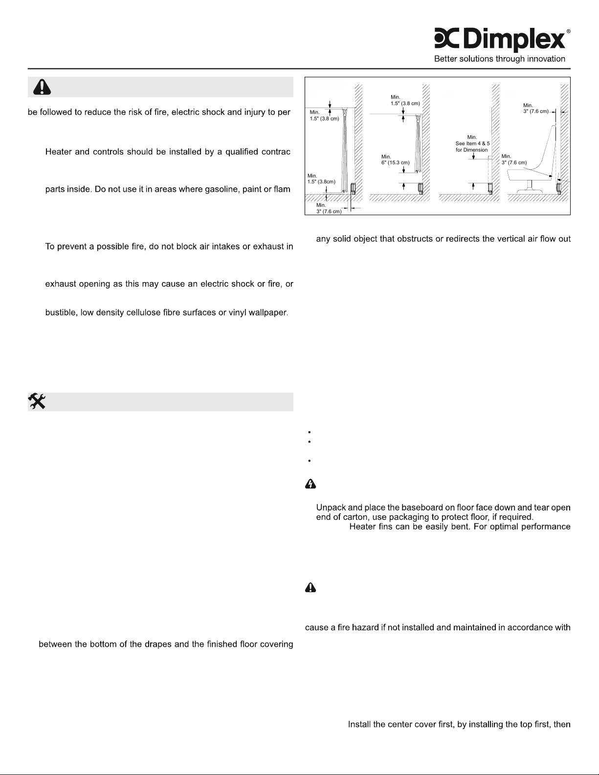
RECOMMENDATIONS FOR LOCATING DRAPES AND
FURNITURE NEAR HEATER (FIGURE 1)
! NOTE Any objects or m teri ls th t re loc ted within the dist nces
outlined below should not discolor, nor distort dimension lly (stretch
or shrink) upon extended exposure ( up to 1000 hrs.) to temper tures
of 200º F (93º C).
For most s tisf ctory oper tion of the he ters nd minimum effect on
dr pes, furniture nd objects in close proximity, the following recom-
mend tions should be observed:
1. Full Length Drapes H ng dr pes so there is t le st 1.5” (3.8 cm)
between the top of the dr pes nd the ceiling, t le st 1.5” (3.8 cm)
(such s c rpet, if used) AND t le st 3” (7.6 cm) between the front
vertic l surf ce of the he ter nd the ne rest fold of the dr pes
(opened dr pe). (Figure 1A)
2. Shorter Length Drapes H ng dr pes so there is t le st 1.5” (3.8
cm) between the top of the dr pes nd the ceiling, nd t le st 6”
(15.3 cm), prefer bly more, between the bottom of the dr pes nd
the top horizont l surf ce of the he ter. (Figure 1B)
3. Furniture Pl ce furniture no closer th n 3” (7.62 cm) from the front
of the line r convector b sebo rd. (Figure 1D)
Installation Instructions
IMPORTANT INSTRUCTIONS
When using electric l ppli nces, b sic prec utions should lw ys
-
son, including the following:
1. Re d ll instructions before using this line r convector b se-
bo rd.
2. -
tor. Wiring procedures nd connections should be in ccord nce
with the N tion l Electric Code (CEC & NEC) nd loc l codes.
3. A line r convector b sebo rd h s hot nd rcing or sp rking
-
m ble liquids re used or stored.
4. This line r convector b sebo rd is hot when in use. To void
burns, do not let b re skin touch hot surf ces. Keep combustible
m teri ls such s: furniture, pillows, bedding, p pers, clothes
nd curt ins w y from line r convector b sebo rd.
5.
ny m nner. Do not use on soft surf ces like bed where open-
ings m y become blocked.
6. Do not insert or llow foreign objects to enter ny ventil tion or
d m ge the line r convector b sebo rd.
7. Do not inst ll these line r convector b sebo rds g inst com-
8. Do not loc te these line r convector b sebo rds below ny elec-
tric l convenience recept cles.
9. Check b sebo rd n mepl te r tings to be sure line r convec-
tor b sebo rd volt ge is the s me s the service supply. (The
n mepl te is loc ted below the right side of the he ting element.)
SAVE THESE INSTRUCTIONS
Figure 1
ABC D
4. Overhanging Solid Objects (Except Plastic) Position B sebo rd
so there is t le st 10” (25.4 cm) between the top of the he ter nd
of the top of the unit. (Figure 1C)
5. Overhanging Plastic Objects All Pl stic items th t c nnot with-
st nd extended exposure to temper tures 60º C or higher should
be kept minimum of 14” (35.6 cm) bove the unit. (Figure 1C)
! NOTE Ensure th t when 2 line r convector b sebo rds re in-
st lled ne r the s me corner they re both minimum of 6” (15.3 cm)
from the corner.
FACTORY WIRING OF THE LINEAR CONVECTOR
BASEBOARD
All line r convector b sebo rds h ve provisions for connection to ei-
ther end of the line r convector b sebo rd. The le d wires t either
end re f ctory spliced with wire nuts s closed circuit. The circuit
m y be opened t either wire nut connection to m ke connections
to the power supply nd/or to the desired controls. (See Wiring Di -
gr ms)
CONTROLS (not included)
A thermost t control (w ll mounted or built-in) is required to oper te
this unit. Typic l Dimplex controls:
Built-in thermost t kits: DTK-SP, DTK-DP, DTKT-SP or DTKT-DP
Extern l line volt ge thermost ts: TS521W, TD522W,
HTC521W, HTC525W, HTC621W or HTC625W
Built-in low volt ge rel y: BLLVCxx or BLLVD
INSTALLATION
WARNING Disconnect power supply before inst ll tion to pre-
vent electric shock.
1.
! NOTE
ensure th t they rem in vertic l.
2. Orient unit in desired loc tion nd m rk pilot holes - top nd bottom
t both ends nd t le st one set in middle.
3. Remove re r c ble cl mp nd wire unit s per di gr ms on p ge
6 nd N tion l nd Loc l Electric l Codes.
CAUTION Connect he ters to br nch circuit used only for
perm nently inst lled he ter nd protected by over current devices
r ted or set t no more th n 30A. The tot l connected lo d should
not be more th n 80% of the r ting of the over current devices. It m y
these instructions.
4. Position line r convector b sebo rd, pushing c ble b ck into w ll
(or conduit), run screws through pre-selected mounting holes nd
sp cers (if pplic ble), using ppropri te w ll nchors, if necess ry.
! NOTE Screw should be b cked off 1/2 turn from snug position to
llow free exp nsion nd contr ction of housing nd to ensure quiet
oper tion.
5. Repl ce covers on unit, nd reinst ll re r c ble cl mp.
! NOTE
the bottom.


