Buchi C-660 User manual

Fraction Collector C-660
Operation Manual
096969 en

Imprint
Product Identification:
Operation Manual (Original), Fraction Collector C-660
096969 en
Publication date:
08.2015, Version D
BÜCHI Labortechnik AG
Meierseggstrasse 40
Postfach
CH-9230 Flawil 1
E-Mail: quality@buchi.com
BUCHI reserves the right to make changes to the manual as deemed necessary in the light of experience; espe-
cially in respect to structure, illustrations and technical detail.
This manual is copyright. Information from it may not be reproduced, distributed, or used for competitive pur-
poses, nor made available to third parties. The manufacture of any component with the aid of this manual with-
out prior written agreement is also prohibited.

Table of contents
3
C-660 Operation Manual, Version F
Table of contents
1 About this manual . . . . . . . . . . . . . . . . . . . . . . . . . . . . . . . . . . . . . . .5
1.1 Reference documents. . . . . . . . . . . . . . . . . . . . . . . . . . . . . . . . . .5
1.2 Trademarks . . . . . . . . . . . . . . . . . . . . . . . . . . . . . . . . . . . . . . . 5
1.3 Abbreviations . . . . . . . . . . . . . . . . . . . . . . . . . . . . . . . . . . . . . . 5
2 Safety. . . . . . . . . . . . . . . . . . . . . . . . . . . . . . . . . . . . . . . . . . . . . .6
2.1 User qualification . . . . . . . . . . . . . . . . . . . . . . . . . . . . . . . . . . . . 6
2.2 Proper use . . . . . . . . . . . . . . . . . . . . . . . . . . . . . . . . . . . . . . . 6
2.3 Improper use . . . . . . . . . . . . . . . . . . . . . . . . . . . . . . . . . . . . . . 6
2.4 Warning notices used in this manual . . . . . . . . . . . . . . . . . . . . . . . . . . 7
2.5 Product safety. . . . . . . . . . . . . . . . . . . . . . . . . . . . . . . . . . . . . .7
2.5.1 Instrument-related hazards . . . . . . . . . . . . . . . . . . . . . . . . . . . . . . . 7
2.5.2 Other hazards . . . . . . . . . . . . . . . . . . . . . . . . . . . . . . . . . . . . . .8
2.5.3 Safety measures . . . . . . . . . . . . . . . . . . . . . . . . . . . . . . . . . . . . 8
2.6 General safety rules . . . . . . . . . . . . . . . . . . . . . . . . . . . . . . . . . . . 8
3 Technical data . . . . . . . . . . . . . . . . . . . . . . . . . . . . . . . . . . . . . . . . . 9
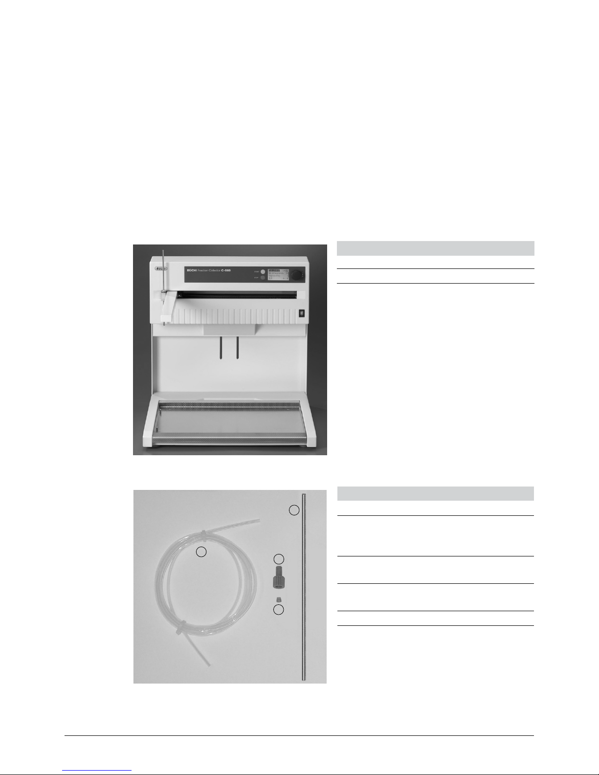
3.1 Scope of delivery . . . . . . . . . . . . . . . . . . . . . . . . . . . . . . . . . . . . 9
3.1.1 Standard instrument. . . . . . . . . . . . . . . . . . . . . . . . . . . . . . . . . . .9
3.1.2 Standard accessories . . . . . . . . . . . . . . . . . . . . . . . . . . . . . . . . . . 9
3.1.3 Optional accessories . . . . . . . . . . . . . . . . . . . . . . . . . . . . . . . . . 10
3.2 Materials used. . . . . . . . . . . . . . . . . . . . . . . . . . . . . . . . . . . . . 12
3.3 Technical data overview . . . . . . . . . . . . . . . . . . . . . . . . . . . . . . . . 12
4 Description of function . . . . . . . . . . . . . . . . . . . . . . . . . . . . . . . . . . . 14
4.1 Overview over the instrument . . . . . . . . . . . . . . . . . . . . . . . . . . . . . 14
4.2 Function prinicple . . . . . . . . . . . . . . . . . . . . . . . . . . . . . . . . . . . 14
5 Putting into operation . . . . . . . . . . . . . . . . . . . . . . . . . . . . . . . . . . . . 15
5.1 Installation site. . . . . . . . . . . . . . . . . . . . . . . . . . . . . . . . . . . . . 15
5.2 Electrical connections . . . . . . . . . . . . . . . . . . . . . . . . . . . . . . . . . 15
5.3 Installation. . . . . . . . . . . . . . . . . . . . . . . . . . . . . . . . . . . . . . . 16
5.3.1 Power connection . . . . . . . . . . . . . . . . . . . . . . . . . . . . . . . . . . . 16
5.3.2 Fitting and ferrule . . . . . . . . . . . . . . . . . . . . . . . . . . . . . . . . . . . 16
5.3.3 Optional waste diverter valve . . . . . . . . . . . . . . . . . . . . . . . . . . . . . 16
Read this manual carefully before installing and running your system and note the safety precautions
in chapter 2 in particular. Store the manual in the immediate vicinity of the instrument, so that it can be
consulted at any time.
No technical modifications may be made to the instrument without the prior written agreement of
BUCHI. Unauthorized modifications may affect the system safety or result in accidents.
This manual is copyright. Information from it may not be reproduced, distributed, or used for competi-
tive purposes, nor made available to third parties. The manufacture of any component with the aid of
this manual without prior written agreement is also prohibited.
The English manual is the original language version and serves as basis for all translations
into other languages. Other language versions can be downloaded at www.buchi.com.

Table of contents
4
C-660 Operation Manual, Version F
6 Operation . . . . . . . . . . . . . . . . . . . . . . . . . . . . . . . . . . . . . . . . . . 18
6.1 Control elements . . . . . . . . . . . . . . . . . . . . . . . . . . . . . . . . . . . 18
6.2 Display . . . . . . . . . . . . . . . . . . . . . . . . . . . . . . . . . . . . . . . . 19
6.3 Operating the instrument . . . . . . . . . . . . . . . . . . . . . . . . . . . . . . . 20
6.3.1 Remote Control . . . . . . . . . . . . . . . . . . . . . . . . . . . . . . . . . . . . 20
6.3.2 Manual control / manual mode . . . . . . . . . . . . . . . . . . . . . . . . . . . . 21
6.3.3 Setting the height of the collector arm . . . . . . . . . . . . . . . . . . . . . . . . . 24
6.3.4 Interface RS 232 . . . . . . . . . . . . . . . . . . . . . . . . . . . . . . . . . . . 25
6.3.5 Peak detection . . . . . . . . . . . . . . . . . . . . . . . . . . . . . . . . . . . . 25
7 Maintenance . . . . . . . . . . . . . . . . . . . . . . . . . . . . . . . . . . . . . . . . . 28
7.1 Cleaning. . . . . . . . . . . . . . . . . . . . . . . . . . . . . . . . . . . . . . . . 28
8 Troubleshooting . . . . . . . . . . . . . . . . . . . . . . . . . . . . . . . . . . . . . . . 29
8.1 Malfunctions and their remedy. . . . . . . . . . . . . . . . . . . . . . . . . . . . . 29
8.2 Customer service . . . . . . . . . . . . . . . . . . . . . . . . . . . . . . . . . . . 30
9 Shutdown, storage, transport and disposal . . . . . . . . . . . . . . . . . . . . . . . . 31
9.1 Storage and transport . . . . . . . . . . . . . . . . . . . . . . . . . . . . . . . . . 31
9.2 Disposal. . . . . . . . . . . . . . . . . . . . . . . . . . . . . . . . . . . . . . . . 31
10 Spare parts. . . . . . . . . . . . . . . . . . . . . . . . . . . . . . . . . . . . . . . . . . 32
11 Declarations and requirements. . . . . . . . . . . . . . . . . . . . . . . . . . . . . . . 33
11.1 FCC requirements (for USA and Canada) . . . . . . . . . . . . . . . . . . . . . . . 33
11.2 Declaration of conformity . . . . . . . . . . . . . . . . . . . . . . . . . . . . . . . 34

1 About this manual
5
C-660 Operation Manual, Version F
1 About this manual
This manual describes the Fraction Collector C-660 and provides all information required for its safe
operation and to maintain it in good working order.
It is addressed in particular to laboratory personnel and operators.
NOTE
The symbols pertaining to safety (WARNINGS and ATTENTIONS) are explained in chapter 2.
1.1 Reference documents
• Installation Guide SepacoreControl
• Pump Modules C-601 & C-605, Pump Controller C-610 / Pump Manager C-615,
Operation Manual numbers 96961 – 96965
• UV-Monitor C-630, Operation Manual numbers 96950 – 96953 and 96966
• UV-Photometer C-635, Operation Manual numbers 96957 – 96960 and 96967
• Cartridger C-670, Operation Manual numbers 96945 – 96949
1.2 Trademarks
The following product names and any registered and unregistered trademarks mentioned in this
manual are used for identification purposes only and remain the exclusive property of their respective
owners:
• Sepacore®is a registered trademark of BÜCHI Labortechnik AG
• Syncore®is a registered trademark of BÜCHI Labortechnik AG
• Cartridger®is a registered trademark of BÜCHI Labortechnik AG
1.3 Abbreviations
ETFE: Ethylene/Tetrafluoroethylene Copolymer
FEP: Fluorinated Ethylene Propylene
POM: Polyoxymethylene
PUR: Polyurethane

2 Safety
6
C-660 Operation Manual, Version F
2 Safety
This chapter highlights the safety concept of the fraction collector and contains general rules of
behavior and warnings from hazards concerning the use of the product.
The safety of users and personnel can only be ensured if these safety instructions and the safety-
related warnings in the individual chapters are strictly observed and followed, therefore, the manual
must always be available to all persons performing the tasks described herein.
2.1 User qualification
The instrument may only be used by laboratory personnel or other persons who on account of training
or professional experience have an overview of the dangers which can develop when operating the
instrument.
Personnel without this training or persons who are currently being trained require careful supervision.
The present Operation Manual serves as a basis for training.
2.2 Proper use
The Fraction Collector C-660 has been conceived of and constructed as a laboratory instrument. Its
correct usage is the optimal and reliable collection of individual aqueous and/or organic fractions in
predetermined or customized racks (e.g. chromatography or Syncore racks).
Correct usage of the Fraction Collector C-660 also includes its maintenance and careful handling of
the instrument on the basis of the specifications given in the Operation Manual.
2.3 Improper use
Applications beyond those described above are improper. Furthermore, applications which do not
comply with the technical data are also considered improper. The operator bears the sole risk for any
damages caused by such improper use.
The following applications are expressly forbidden:
• Use of the instrument in rooms which require ex-protected instruments.
• Collection of samples which can explode or inflame due to shock, friction, heat or spark formation
or that are combustible (e.g. explosive substances, etc.)
• Use in human medicine diagnostics.
• Preparation of food.

2 Safety
7
C-660 Operation Manual, Version F
2.4 Warning notices used in this manual
WARNING
Generally, the triangular warning symbol indicates the possibility of personal injury or even loss of life
if the instructions are not followed.
WARNING
Electrical hazard.
WARNING
Harmful to life forms.
WARNING
Inhalation of harmful substances.
ATTENTION
With the “Read this” symbol, ATTENTION indicates the possibility of equipment damage, malfunctions
or incorrect process results if the instructions are not followed.
NOTE
Useful tips for the optimum operation of the instrument.
2.5 Product safety
The Pump System is designed and built in accordance with current state-of-the-art technology,
however, risks to users, property, and the environment can arise when the instrument is used care-
lessly or improperly.
The manufacturer has determined residual dangers emanating from the instrument
• if the instrument is operated by insufficiently trained personnel.
• if the instrument is not operated according to its proper use.
Appropriate warnings in this manual serve to make the user alert to these residual dangers.
2.5.1 Instrument-related hazards
Pay attention to the following safety notices:
WARNING
Potential risk in case of damaged glassware.
• Beware of shivering glass parts.
• Beware of defective FEP tubing.
• Beware of leaky connections and insufficiently long connection tubings.
• Beware of defective valves.
• Beware of a false positioning of the collector arm

2 Safety
8
C-660 Operation Manual, Version F
WARNING
Potential risk if solvent vapors accumulate within the instrument housing.
• Beware of damaged or cracked glass parts.
• Beware of dangerous, flammable or explosive samples.
• Operate the instrument in a fume hood or in an adequately ventilated work area.
2.5.2 Other hazards
WARNING
Certain solvents within or in the vicinity of the Pump Systems can form peroxides and/or are highly
inflammable.
• Always be aware of the explosion risk when working with hazardous substances or with
substances of unknown composition.
• Always use the instrument in an adequately ventilated work area.
2.5.3 Safety measures
Always wear personal protective equipment such as protective goggles, protective clothing and gloves
when working with the instrument.
2.6 General safety rules
Responsibility of the operator
The head of laboratory is responsible for training his personnel.
The operator shall inform the manufacturer without delay of any safety-related incidents which might
occur during the operation of the instrument. Legal regulations, such as local, state and federal laws
applying to the instrument must be strictly followed.
Duty of maintenance and care
The operator is responsible for ensuring that the instrument is only operated in proper manner and
that maintenance, service, and repairs are performed with care, on schedule and by authorized
personnel only.
Spare parts to be used
Use only recommended consumables and spare parts for maintenance to ensure continued optimum
system performance and reliability. Any modifications to the spare parts used are only allowed with the
prior written permission of the manufacturer.
Modifications
Modifications to the instrument are only permitted after prior consultation with and written approval
obtained from the manufacturer. Modifications and upgrades should only be carried out by an autho-
rized BUCHI technical engineer. The manufacturer reserves the right to decline any claim resulting from
unauthorized modifications.

3 Technical data
9
C-660 Operation Manual, Version F
3 Technical data
This chapter introduces the reader to the fraction collector and its main components. It contains tech-
nical data, requirements and performance data.
3.1 Scope of delivery
Check the scope of delivery according to the order number.
NOTE
For detailed information on the listed products, see www.buchi.com or contact your local dealer.
3.1.1 Standard instrument
Table 3-1: Standard instrument
Product Order number
Fraction Collector C-660 44900
3.1.2 Standard accessories
1
3
4
2
Table 3-2: Standard accessories
Product Order number
a FEP tubing, 1/8”×1/16”, 5 m, green
FEP tubing thin, 1/16”×1/32”, 5 m,
gray
44354
44357
b 25 fittings, 1/8”, green
25 fittings, 1/16”, gray
40956
44816
c 25 ferrules, 1/8” green
25 ferrules, 1/16” gray
40961
44269
d Tubing guide 20780

3 Technical data
10
C-660 Operation Manual, Version F
Table 3-2: Standard accessories (cont.)
Product Order number
Regional power cord, 1.5 m:
Type CH 10010
Type Schuko (D,F) 10016
Type GB 17835
Type USA 10020
Type AUS 17836
Operation Manual:
German 96968
English 96969
Spanish 96970
French 96971
Italian 96972
3.1.3 Optional accessories
Table 3-3: Optional accessories
Product Order number
Waste valve, valve for the Fraction
Collector. Prevents dripping during the
fraction change.
51114
Tubing fitting set for connecting the
waste valve.
44021
Waste level sensor, optimal accessory for
the Fraction Collector. Mounted at the top
of the waste bottle the float type switch
prevents the running over of the waste
reservoir. Connector for GL 45 glass
threads.
45288

3 Technical data
11
C-660 Operation Manual, Version F
Table 3-3: Optional accessories (cont.)
Product Order number
6
7
8
9
10
5
e 4 racks FC 12, set of 4 racks FC 12
– each for 12 tubes at 250 mL with a
diameter of 40 mm (without tubes).
44957
f 4 racks FC 30, set of 4 racks FC 30
– each for 30 tubes at 50 mL with
diameter of 26 mm (without tubes).
44958
g 4 racks FC 60, Set of 4 racks FC 60
– each for 60 tubes at 20 mL with
diameter of 17 mm (without tubes).
44959
h 10×250 mL tubes for rack FC 12,
diameter of 39 mm; height of 300 mm
44960
i 20×50 mL tubes for rack FC 30,
diameter of 25 mm; height of 185 mm
44961
j 100×20 mL tubes for rack FC 60,
diameter of 16 mm; height of 160 mm
44962
11
Chromatography table
Pivoting table for the integration of
two pump modules, detectors, fraction
collector including support rod holder.
54290
12
Chromatography table with monitor
holder
Pivoting table for the compact integra-
tion of the Control Unit C-620, two pump
modules, detectors, fraction collector and
PC including monitor.
Easy access and safe working due to
clearly visible tubing guides. PC and
monitor are not included.
54292

3 Technical data
12
C-660 Operation Manual, Version F
3.2 Materials used
Table 3-4: Materials used
Component Material designation
Housing PUR foam
Tubing FEP
Fitting POM
Ferrule ETFE
Drip tray Steel
Chromatography table Aluminum
3.3 Technical data overview
Table 3-5: Technical data
Dimensions ( W×D) 465×470 mm
Height (H) Adjustable from 370 mm to 460 mm
Weight 14 kg
Connection voltage 100 – 230 VAC ± 15%
Power consumption max. 25 W
Frequency 50/60 Hz
Installation category II
Degree of protection IP20
Pollution degree 2
Environmental conditions
Temperature
Altitude
Humidity
for indoor use only
5 – 40 °C
up to 2000 m
maximum relative humidity 80% for temperatures up to
31 °C, and then linearly decreasing to 50% at 40 °C
Support racks 4× FC60: 4×(60×20 mL tubes)
4× FC30: 4×(30×50 mL tubes)
4× FC12: 4×(12×250 mL tubes)
Syncore racks (R4, R6, R12, R24, R48, R96)
Teach-in-function of 11 user-specific racks
Collection area (W×D) 440 mm×350 mm
Collection modes Time (interval timer 1 s – 100 h)
Volume (only with BUCHI Sepacore pumps)
Peak threshold (together with a detector)

3 Technical data
13
C-660 Operation Manual, Version F
Table 3-5: Technical data (cont.)
Fuse T500 mA L 250 V
Peak detection types Peak threshold
Peak detection, number Monitoring of 1 or 2 detector signals
Display Back-lit LCD graphic display 28×64 pixels (58×29 mm)
Dialog languages en / de / fr / it / es / jp
Interfaces 2× RS - 485 (system bus)
1× RS - 232 (process data output)
1× Mini-DIN (waste valve)
1× Mini-DIN (TTL In / alarm monitoring and/or ext. start)
1× Mini-DIN (level sensor for waste container)
2× Cinch In (detector signal input)
2× Cinch Out (detector signal and fraction change
marker)
Certificate CSA C, US

4 Description of function
14
C-660 Operation Manual, Version F
4 Description of function
This chapter explains the basic principle of the fraction collector and provides a functional description
of the assemblies.
The design of the fraction collector enables the automatic collection of both organic and aqueous
fractions without metal contact.
4.1 Overview over the instrument
2
4
7
13
5
6
a Tubing guide
bFEP tubing
c Collector arm
d Controls
e ON/OFF switch
fFC 60 rack with glass
tubes
g Drip tray
Fig. 4.1: Example of System 3
4.2 Function principle
The fraction collector is characterized by the following features:
• Up to 12 liters (48×250 mL) or up to 240 fractions of 20 mL can be collected.
• All Syncore racks are predefined.
• A simple teach-in enables the definition of up to 11 user-specific rack types.
Other features include:
• Fractionation with or without detector.
• Integrated RS-232 interface for data transfer to PC.
• Integrated peak detector.
• Two detector inlets and two recorder outlets.
• Optional monitoring of the waste bottle level.
• Optional waste diverter valve recommended for flow rates > 10 mL/min.

5 Putting into operation
15
C-660 Operation Manual, Version F
5 Putting into operation
This chapter describes the installation of the fraction collector and gives instructions on initial start-up.
NOTE
Inspect the instrument for damages during unpacking. If necessary, prepare a status report imme-
diately to inform the postal company, railway company or transport company. Keep the original
packaging for future transport.
5.1 Installation site
Place the instrument on a stable, horizontal surface, so that the rear side remains accessible and
consider the maximum product dimensions.
To avoid annoyance caused by bad smells or possible damage to health caused by volatile solutions,
we recommend setting up the Fraction Collector C-660 with an exhaust system. It should thereby be
ascertained that the instrument is not exposed to aggressive substances such as acids, bases and
solvents, which can have a negative influence on the useful life.
WARNING
The fraction collector is not explosion proof. Potential explosion risk.
• Never position potential ignition sources near the Fraction collector.
• Operate the instrument in a fume hood or in an adequately ventilated work area.
5.2 Electrical connections
ATTENTION
Make sure that the voltage on the socket corresponds to the voltage given on the type plate of the
instrument.
Ensure that the instrument is earthed. External connections and extension cables must be provided
with an earthed conductor lead (3-pole couplings, cable or plug equipment) as the mains lead has a
molded plug to avoid risks due to inadvertent defective wiring.
Make sure that no electric sparks form in the instrument or its surroundings as they might damage
the instrument.
An electrostatic discharge can damage the instrument and lead to fire.

5 Putting into operation
16
C-660 Operation Manual, Version F
5.3 Installation
5.3.1 Power connection
Connect the power cord.
Fig. 5.1: Connecting the power cord
5.3.2 Fitting and ferrule
1
23
The tubing acontaining the fraction comes
from the chromatography column. The fitting
band ferrule care attached to the free end.
Mount the fitting band ferrule c.
Press the suction tubing aand the ferrule c
against a table surface to firmly seal the tubing
end with the ferrule.
Fig. 5.2: Installing fitting and ferrule
5.3.3 Optional waste diverter valve
If the flow rate of the pumps exceeds 10 mL/
min a waste diverter valve is recommended.
To install the waste diverter valve, proceed as
follows:
Screw the tubing coming from the detector
into the inlet a. Outlet bleads to the collec-
tion arm of the fraction collector.
Ensure that the FEP tubing cis long enough
to reach even the farest corner position of the
collector arm h. Outlet dleads to the waste
bottle.
The waste diverter valve can be fixed at the
back side of the fraction collector.
3
4
2
1
2
4

5 Putting into operation
17
C-660 Operation Manual, Version F
3
6
7
8
The collector head e is found on the collec-
tor arm hof the fraction collector. Clamp the
tubing guide f(metal pipe) tightly into the
collector head g.
Ensure that the height of the tubing guide f
is correct. It should be at least 1 cm above the
tube rim, so that it will not damage the tubing
during operation.
Now direct the FEP-tubing cfrom valve out-
let band afterwards through the tubing guide
f, so that it pokes out approximately 3 mm.
Connect the valve to the WASTE VALVE con-
nection i.
9
Fig. 5.3: Installating the waste diverter valve
234
18
5
6 7 910
Fig. 5.4: Control arrangement on the Pump Controller
a Power cord
bFUSE 0.5 AT: Fuse
c WASTE VALVE: Valve control
d WASTE LEVEL: Monitoring of valve bottle
level
e TTL IN/OUT: TTL connection
fDETECTOR IN 1,2: Detector inputs 1 + 2
g X-T RECORDER 1,2: Chart recorder outlets
1 + 2
h RS 232: Series data interfaces
i RS 485: 2× bus interface for peripheral
devices (fraction collector, pumps, etc.)
j Address bus switch for remote control
position 1 or 2 for SepacoreControl,
position 0 for manual mode

6 Operation
18
C-660 Operation Manual, Version F
6 Operation
This chapter explains the operating elements and possible operating modes. It gives instructions on
how to operate the Fraction collector properly and safely.
ATTENTION
Check the glassware for damages prior to each operation and use only glassware in perfect condi-
tion. Glassware with cracks, stars or other damages can fail during operation.
Make sure that all fittings and tubings are hand-tight.
6.1 Control elements
1
234
5
a START/NEXT button
bSTOP/PAUSE button
c Display
d Selector switch (turn and press knob)
e ON/OFF (Power switch)
Fig. 6.1: Control elements of the fraction collector
Table 6-1: Functions of the Main Menu
Control Function
START/NEXT button
(green)
Starts the fraction collector from the rest or pause status. Simultaneously starts the
connected pump system. Carries out a tube change when the instrument is running.
STOP/PAUSE button
(red)
Pressing once results in pause, pressing twice stops the program.
Display Displays parameters and values.
Selector switch
(turn and press
knob)
Menu operation by turning and pressing.
ON
OFF
Power ON/OFF switch

6 Operation
19
C-660 Operation Manual, Version F
6.2 Display
Navigation mode Editing mode
Status line
Mode line
Fig. 6.2: Overview of the display
The display is divided into Status and Mode lines. The status line is fixed. On the left side it shows the
five potential states of the Fraction Collector. On the right side the status line shows the remaining lead
time, the remaining collection time or the residual volume of the relevant fraction.
The following states are possible:
Table 6-2: Instrument states
Status Description
Collect The fractions can be collected according to time, or volume.
Delay The solvent is directed into the waste container. The actual collection procedure begins only
after the end of the lead time.
The fraction collector is in collection status:
PAUSE Pressing the STOP/Pause button once The program sequence is interrupted and the BUCHI
pump modules are stopped (no reset).
Other brand pumps will not be stopped. The program
sequence is continued with the START key.
STOP Pressing the STOP/Pause button twice The fraction collector stops and the collector arm
returns to its initial position. Running programs are
permanently aborted. The pump modules are stopped.
START Pressing the START/NEXT button once The collector arm changes to the next tube.
The fraction collector is in pause status:
STOP Pressing the STOP/Pause button once The fraction collector stops and the collector arm
returns to its initial position. Running programs are
permanently aborted. The pump modules are stopped.
START Pressing the START/NEXT button once The program sequence is continued.
ERROR The error number is displayed and the START/STOP keys are locked. Report the incidence to the
BUCHI customer service.

6 Operation
20
C-660 Operation Manual, Version F
The mode line shows the navigation and editing mode you are in. It can be controlled with the selector
switch by rotating and pressing.
Parameters surrounded by lines cannot be
changed.
Fig. 6.3: Parameters surrounded by lines
Parameters highlighted with black background
can be selected and changed. The scroll bar on
the right indicates your position within the menu.
Fig. 6.4: Parameters highlighted with black background
With the selector switch you can navigate through the menu. You select the desired parameters by
turning the knob, and confirm your selection by pressing it. The cursor jumps into the editing mode or,
if it is already in the editing mode, into the next line (for program operation only in the stop mode). You
set the desired values by turning the selector switch. Press the selector switch in order to confirm the
new value. After 10 seconds without confirmation the cursor jumps back to the old parameters and
into the navigation mode.
6.3 Operating the instrument
Turn on the fraction collector with the Power ON/OFF switch. The display shows the software version
for a few seconds. The main menu with the last used values and parameters now appears automati-
cally.
You can move through the menu by turning the selector switch. Select your parameters or compose a
new program.
6.3.1 Remote Control
If the fraction collector is part of a system controlled by SepacoreControl, “Remote Control” is indi-
cated on the display. In this mode no menu is accessible.
For this purpose set the address bus switch to position 1 or 2 (see Fig. 5.4). Now all settings have to
be done within the SepacoreControl software (see Installation Guide SepacoreControl).
Table of contents
Other Buchi Laboratory Equipment manuals

Buchi
Buchi K-370 User manual

Buchi
Buchi S-300 User manual

Buchi
Buchi Rotavapor R-220 User manual

Buchi
Buchi Syncore User manual

Buchi
Buchi HydrolEx H-506 User manual

Buchi
Buchi Rotavapor R-100 User manual

Buchi
Buchi R-210 User manual

Buchi
Buchi K-314 User manual

Buchi
Buchi Inert Loop S-395 User manual

Buchi
Buchi K-424 User manual

Buchi
Buchi Rotavapor R-300 User manual

Buchi
Buchi K-437 User manual

Buchi
Buchi S-300 User manual

Buchi
Buchi KjelMaster K-375 User manual

Buchi
Buchi FatExtractor E-500 User manual

Buchi
Buchi Rotavapor R-220 SE User manual

Buchi
Buchi Process Analyser X-One User manual

Buchi
Buchi Pure C-805 User manual

Buchi
Buchi ProxiMate User manual

Buchi
Buchi Pure C-805 User manual