manuals.online logo
Brands
  1. Home
  2. •
  3. Brands
  4. •
  5. DMP Electronics
  6. •
  7. Keypad
  8. •
  9. DMP Electronics Security Command 670 User manual

DMP Electronics Security Command 670 User manual

Description
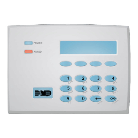
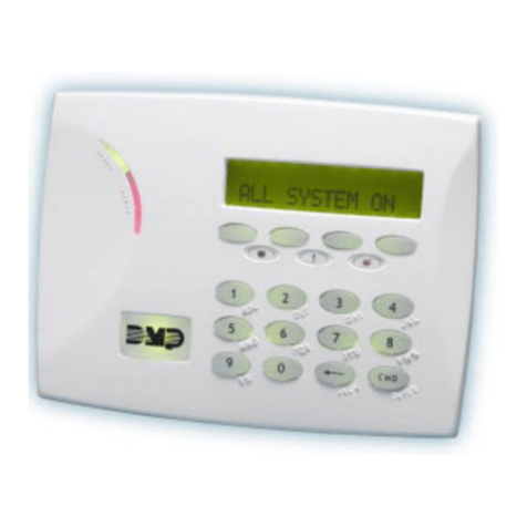
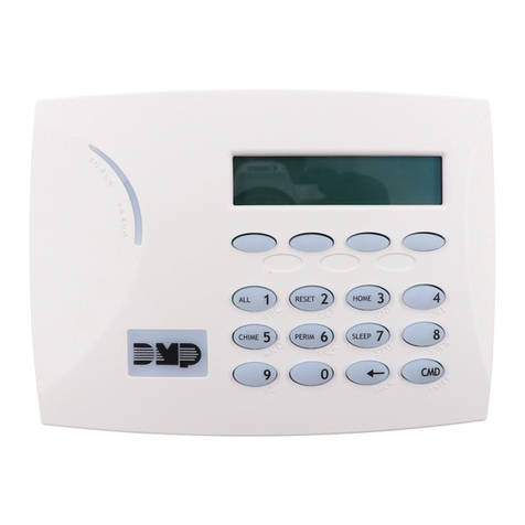
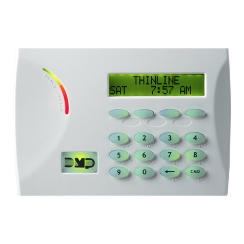
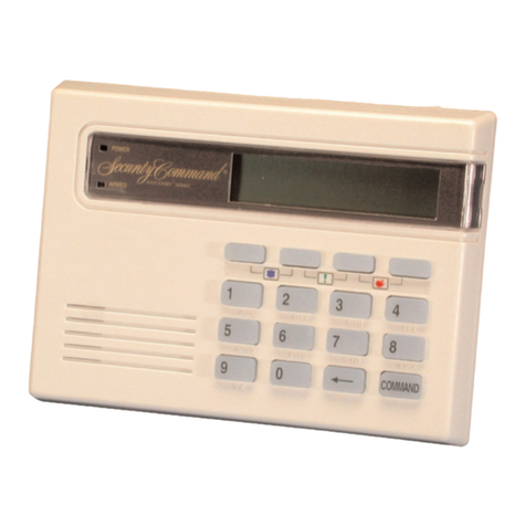
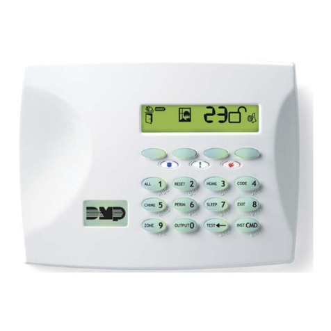
The DMP 670, 770, and 771 Security Command keypads
provide an attractive, user friendly control with optional 2-
buttonPanickeysforusewithDMPCommandProcessor™
panels.Eachkeypadprovidessupervisedorunsupervised
operation, an easy to read 16 character fluorescent blue
display, AC LED, backlit keyboard, low profile styling, and
choice of designer colors to compliment a variety of room
decors.
The770and771 keypadsalsoprovidefour programmable
expansion zones to which you can connect a variety of
burglaryandnon-poweredfiredevices.The771additionally
providesaninternal FormCdoor strikerelayfor controlling
magnetic locks or electric door strikes on protected
entrances.
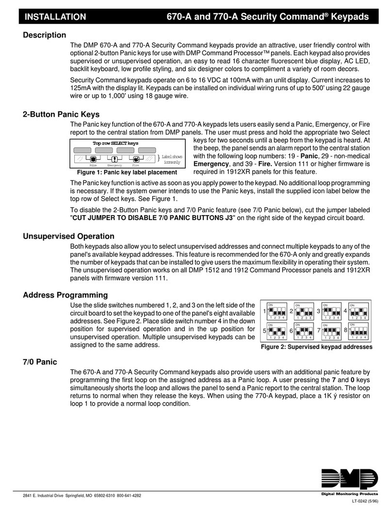
2-Button Panic Keys
The 670, 770, and 771 keypads also provide an optional
Panic key function that lets users easily send a Panic,
Emergency, or Fire report to the central station. The user
just presses and holds two top row Select keys for two
seconds until a beep from the keypad is heard.
At the beep, the panel sends the following zone alarm
reports to the central station: Panic (left two Select keys) -
Zone 19, non-medical Emergency (center Select keys) -
Zone 29, and Fire (right two Select keys) - Zone 39.For
1912XRpanels, version 111 orhigher firmware isrequired
for this feature.
ThePanickeyfunctionisactiveassoonasyouapplypower
tothekeypad.Noadditionalzoneprogrammingisnecessary.
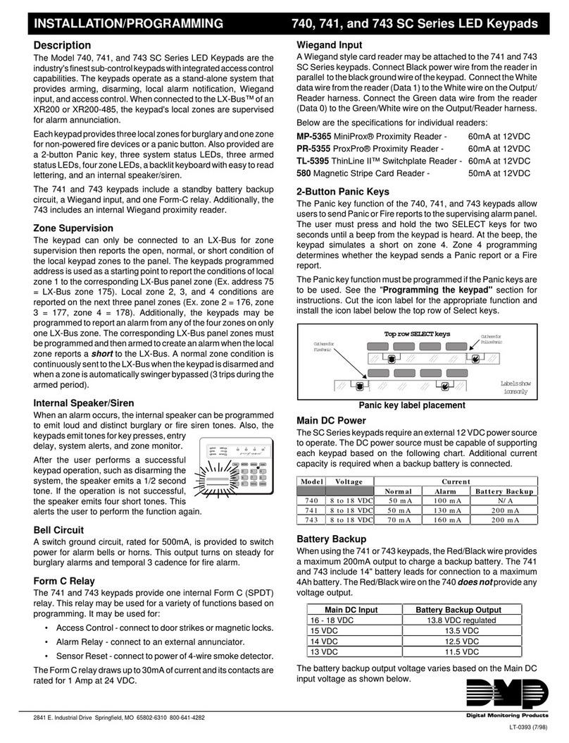
IfthesystemownerintendstousethePanickeys,installthe
supplied icon label below the top row of Select keys.
To disable the 2-Button Panic keys, cut the jumper labeled
"J8" on the bottom left side of the keypad circuit board.
7/0 Panic Keys
The Security Command keypads also allow the user to
initiate a Panic alarm by pressing the 7 and 0 (zero) keys
simutaneously when zone one on the assigned keypad
address is programmed as a Panic type zone.
For the Model 770 and 771 keypads, place a 1k ý End of
Line resistor across the White/Brown pair of zone wires
(zone one).
Todisablethe7/0Panickeyfeature,cutthejumperlabeled
"J7" on the bottom left side of the keypad circuit board.
LT-0110 (5/97)
2841 E. Industrial Drive Springfield, MO 65802-6310 800-641-4282
INSTALLATION 670, 770, and 771 Security Command®Keypads
Unsupervised Operation
The 670, 770, and 771 Security Command keypads also
allow unsupervised operation for connecting multiple
keypadstoone ofthepanel's availablekeypadaddresses.
See Address Programming below. This feature greatly
expands the number of keypads you can install to give
users the maximum flexibility in operating their system.
Unsupervised keypads respond to the panel only when
keys are pressed by the user and work on all DMP panels
and 1912XR panels with firmware version 111 or higher.
Address Programming
Usetheslideswitchesnumbered1,2,and3ontheleftside
of the circuit board to set the keypad to one of the panel's
eight available addresses. See Figure 2.
Moveslideswitch number4
down
forsupervised operationand
up
for unsupervised operation. Multiple unsupervised keypads
can be assigned the same address.
Harness Color Code
Wiring to Panel 770/771 Zone Wiring
Red - Auxiliary Power White/Brown - Zone 1
Yellow - Data Transmit White/Red - Zone 2
Green - Data Receive White/Orange - Zone 3
Black - Ground White/Yellow - Zone 4
Dimming the Keypad Display
Pressing and holding the Command and back arrow keys
for two or more seconds turns off the vacuum fluorescent
display, keyboard backlighting, and Power LED as an
addedcustomerconvenience.Theseindicatorsarerestored
whenever the keypad speaker is turned on or any key on
the keyboard is pressed.
The keyboard backlighting turns off automatically after 30
secondsifnokeysarepressedandthetroublebuzzerisnot
active.
Figure 1: Panic key label placement
}Labelshows
iconsonly
Top row SELECT keys
Police Emergency Fire
Figure 2: Supervised keypad addresses
Figure 3: Unsupervised keypad addresses
5
1
8
7
6
4
32
1 2 3 4
ON
1 2 3 4
ON
1 2 3 4
ON
1 2 3 4
ON
1 2 3 4
ON
1 2 3 4
ON
1 2 3 4
ON
1 2 3 4
ON
5
1
8
7
6
4
32
1 2 3 4
ON
1 2 3 4
ON
1 2 3 4
ON
1 2 3 4
ON
1 2 3 4
ON
1 2 3 4
ON
1 2 3 4
ON
1 2 3 4
ON
Self-Test Diagnostics
The 670, 770, and 771 keypads allow you to test all
system keypad functions. To test the keypads:
• Disconnect the red (+12 VDC), yellow, and green
keypad wires from the panel.
• Twist the yellow and green keypad wires together.
Reconnect the red wire to the panel.
TEST 1 DISPLAY TEST
This test begins immediately and scrolls a series of
characters across the display allowing you to visually
inspect each display segment.
Togotothenexttest,presstheCOMMANDkey.Torepeat
a test, press the ARROW key.
TEST 2 KEY TEST
Thisallowsyoutocheckeachkeyforproperoperation.The
displayshows:PRESSKEY—.Asyoupressandholdeach
key, its name is displayed.
TEST 3 ZONE TEST (Not available on the 670 keypad)
This allows you to check each keypad zone for proper
operation. The display shows: L1 L2 L3 L4.
Following each zone number is the status of the zone. (O)
= Open, (–) = OKAY, and (S) = Short.
TEST 4 FUNCTION TEST
This allows you to check the AC LED and keypad tone for
proper operation. The display reads: LED RLY TONE. To
test each function, press the select key beneath its name.
The keyboard backlight turns off during this test. The RLY
(relay) function is only available on 771 keypads.
TEST 5 ADDRESS TEST
Thistest displays theaddress selectionof the keypad.The
display ADDRESS 3 U indicates thekeypad being tested
is set to address 3 and is also unsupervised. Supervised
keypadsshowonlytheaddressnumber.ToendtheAddress
Test, press COMMAND.
Reconnecting the keypad wiring
Disconnecttheredwirefromthepanel.Separatetheyellow
and green keypad wires and reconnect them to the panel.
Connect the red wire to the panel. Press COMMAND to
start the keypad's normal operation.
Additional Diagnostics
If a key is pressed and the keypad has not been polled by
the panel within the past 5 seconds, the keypad displays
SYSTEM BUSY.
Also, if at any time during normal operation a supervised
keypadcannotdetectpollingfromthepanelfor90seconds,
thedisplayshows:SYSTEMTROUBLE.Thiscouldindicate
a broken green wire, reset jumper installed, or a problem
with the keypad.
If a supervised keypad detects polling, but its particular
address is not being polled, the display shows: NON-
POLLED ADDR. To clear this display, check the address
selectiononthekeypadorthenumberofkeypadaddresses
you've assigned during system programming.
2841 E. Industrial Drive Springfield, MO 65802-6310 800-641-4282
Digital Monitoring Products
Additional Power Supply
If current draw for all keypads connected to the panel
exceeds the panel's output, you can provide additional
current by adding an auxiliary power supply. Connect all
keypadGround(common)wirestothenegativeterminalof
the power supply.
Run a jumper wire from the power supply's negative
terminal to terminal 10 of the panel. Connect all keypad
power(+12VDC)wirestothepositiveterminalofthepower
supply.Do NOT connectthe positive terminalof the power
supply to any terminal of the panel.
AC LED
The keypads contain an AC LED that's off when AC power
to the panel is off or while the panel is resetting.
771 Door Strike Relay
The771providesoneFormC (drycontact)relayoutputfor
controlling magnetic locks or electric door strikes on
protecteddoors.ThesedevicesconnecttotheViolet(N/C),
Gray (Common), and Orange (N/O) conductors on the
harness supplied with the 771 keypad. The relay contacts
are rated for 1 Amp at 24 VDC.
Electrical Specifications
The keypads operate on 8 to 16 VDC at 100mA when idle
withthedisplaylit,110mAwiththekeyboardanddisplaylit,
and up to 120mA with the buzzer on steady and all lighting
on.The771 keypad's internal relay candraw an additional
25mA when a door strike is activated.
Youcaninstallindividualkeypadsonwirerunsofupto500'
using 22 gauge wire or up to 1,000' using 18 gauge wire.
Mounting Options
Formountingthekeypadsonsolidorunevenwalls,youcan
use the DMP Model 776 Metal Keypad Backbox. The 776
is 1/2" deep with a baked enamel finish and provides 1/4"
wire entry holes on the back and sides for convenient
wiring.
For applications where conduit is required to the keypad,
use the DMP Model 775 Metal Keypad Backbox. The 775
is1-1/2"deepwiththree1/2"x3/4"knockoutsforconnecting
conduit.
To provide additional protection for the keypad against
tampering or unauthorized use, you can install the DMP
Model 777 Plastic Keypad Cover that provides a wall-
mountedclear 1/8" thick polycarbonatehousing with lifting
cover and integral locking mechanism.
This manual suits for next models

2

Other DMP Electronics Keypad manuals

DMP Electronics 9800 Series Installation guide

DMP Electronics

DMP Electronics 9800 Series Installation guide

DMP Electronics Thinline Aqualite 7000 Series Installation guide

DMP Electronics

DMP Electronics Thinline Aqualite 7000 Series Installation guide

DMP Electronics Aqualite 7560A User manual

DMP Electronics

DMP Electronics Aqualite 7560A User manual

DMP Electronics 9800 Series User manual

DMP Electronics

DMP Electronics 9800 Series User manual

DMP Electronics 9000 Series Installation guide

DMP Electronics

DMP Electronics 9000 Series Installation guide

DMP Electronics Thinline Series User manual

DMP Electronics

DMP Electronics Thinline Series User manual

DMP Electronics 692F Assembly instructions

DMP Electronics

DMP Electronics 692F Assembly instructions

DMP Electronics Thinline 7060 User manual

DMP Electronics

DMP Electronics Thinline 7060 User manual

DMP Electronics 7800 Series Installation guide

DMP Electronics

DMP Electronics 7800 Series Installation guide

DMP Electronics 9000 Series Installation guide

DMP Electronics

DMP Electronics 9000 Series Installation guide

DMP Electronics 7800 Series Installation guide

DMP Electronics

DMP Electronics 7800 Series Installation guide

DMP Electronics Thinline Series User manual

DMP Electronics

DMP Electronics Thinline Series User manual

DMP Electronics 7760 User manual

DMP Electronics

DMP Electronics 7760 User manual

DMP Electronics 7000INT Series Installation guide

DMP Electronics

DMP Electronics 7000INT Series Installation guide

DMP Electronics Thinline Series Installation guide

DMP Electronics

DMP Electronics Thinline Series Installation guide

DMP Electronics 532XR User manual

DMP Electronics

DMP Electronics 532XR User manual

DMP Electronics 9000 Series User manual

DMP Electronics

DMP Electronics 9000 Series User manual

DMP Electronics ePAD 5.0 Operating instructions

DMP Electronics

DMP Electronics ePAD 5.0 Operating instructions

DMP Electronics 9000 Series User manual

DMP Electronics

DMP Electronics 9000 Series User manual

DMP Electronics XR5FC User manual

DMP Electronics

DMP Electronics XR5FC User manual

DMP Electronics 7872 User manual

DMP Electronics

DMP Electronics 7872 User manual

DMP Electronics 691 User manual

DMP Electronics

DMP Electronics 691 User manual

DMP Electronics 781 User manual

DMP Electronics

DMP Electronics 781 User manual

DMP Electronics 7872 User manual

DMP Electronics

DMP Electronics 7872 User manual

Popular Keypad manuals by other brands

Ksenia ergo A KSI2100030.301 WHITE installation manual

Ksenia

Ksenia ergo A KSI2100030.301 WHITE installation manual

CUE keypadCUE-1G user manual

CUE

CUE keypadCUE-1G user manual

CDVI Digicode Series installation manual

CDVI

CDVI Digicode Series installation manual

DSC RF5501-433 installation manual

DSC

DSC RF5501-433 installation manual

AMC K-LCDW800 installation manual

AMC

AMC K-LCDW800 installation manual

Vimar ELVOX 41020 Installer manual

Vimar

Vimar ELVOX 41020 Installer manual

International Electronics prox.pad plus Installer's guide

International Electronics

International Electronics prox.pad plus Installer's guide

BEA 10KEYPADU user guide

BEA

BEA 10KEYPADU user guide

CDVI KCIENSBP installation manual

CDVI

CDVI KCIENSBP installation manual

ELRO SC11 owner's manual

ELRO

ELRO SC11 owner's manual

Comelit VEDO5TPR Technical manual

Comelit

Comelit VEDO5TPR Technical manual

Texecom Premier LCDLP installation guide

Texecom

Texecom Premier LCDLP installation guide

CDVI KCIEN manual

CDVI

CDVI KCIEN manual

Bticino Terraneo 342610 instruction sheet

Bticino

Bticino Terraneo 342610 instruction sheet

FJM security KeyGuardPro SL-500 instructions

FJM security

FJM security KeyGuardPro SL-500 instructions

Clarion iClock 560 instructions

Clarion

Clarion iClock 560 instructions

NAPCO RP2000LED operating guide

NAPCO

NAPCO RP2000LED operating guide

Gemini GEM-DXK2 operating guide

Gemini

Gemini GEM-DXK2 operating guide

manuals.online logo
manuals.online logoBrands
  • About & Mission
  • Contact us
  • Privacy Policy
  • Terms and Conditions

Copyright 2025 Manuals.Online. All Rights Reserved.