DMT 820MS User manual

1MUSCLE STRIP MYOGRAPH SYSTEM - 820MS - USER MANUAL
USER GUIDE

MUSCLE STRIP MYOGRAPH 820MS
USER GUIDE

3MUSCLE STRIP MYOGRAPH SYSTEM - 820MS - USER MANUAL
CONTENTS
Chapter 1 - Muscle Strip Myograph overview .....................................................................................................................................................................3
Chapter 2 - setting up muscle strip myograph....................................................................................................................................................................4
2.1 Changing and adjusting the mounting supports .......................................................................................................................................................4
2.1.1 Changing the mounting supports.................................................................................................................................................................................4
2.2 Calibration of the force transducer...................................................................................................................................................................................5
3.1 Mounting supports and how to mount muscle strips ..............................................................................................................................................6
3.2 Normalization...........................................................................................................................................................................................................................7
3.3 Standard start ...........................................................................................................................................................................................................................7
3.5 In vitro experiment 1: Noradrenaline contractile response.....................................................................................................................................7
3.6 In vitro experiment 2: Acetylcholine relaxation curve...............................................................................................................................................7
Chapter 3 - Cleaning and Maintenance .................................................................................................................................................................................8
3.1 Cleaning the Muscle Strip Myograph .............................................................................................................................................................................8
3.2 Maintenance of the force transducer...............................................................................................................................................................................9
3.2.1 Checking the force transducer........................................................................................................................................................................................9
3.2.2 Force Transducer Replacement.................................................................................................................................................................................... 10
3.3 Maintenance of the micropositioner??......................................................................................................................................................................... 11

4
CHAPTER 1
CHAPTER 1 MUSCLE STRIP MYOGRAPH OVERVIEW
Micropositioner Connection to Interface
Muscle Strip Myograph clamp support
connected to micrometer
Force transducer pin
Muscle Strip Myograph clamp support
connected to force transducer
Figure 1.1 Muscle Strip Myograph with close-up of chamber
Transducer house

5MUSCLE STRIP MYOGRAPH SYSTEM - 820MS - USER MANUAL
CHAPTER 2 SETTING UP MUSCLE STRIP MYOGRAPH
2.1 Changing and adjusting the mounting supports
2.1.1 Changing the mounting supports
2.1.2 Coarse adjusting the jaws for small vessels (gure 2.1)
2.1.3 Fine adjusting the jaws for small vessels (gure 2.2 and gure 2.3)
2.1.4 Fine adjusting the pins for larger vessels (gure 2.4 and gure 2.5):

6
2.2 Calibration of the force transducer
As a part of the general maintenance of the Muscle Strip Myograph, DMT recommends that the Muscle Strip Myograph is force
calibrated at least once a month. The Muscle Strip Myograph should also be force calibrated every time it has been moved. Al-
though lab benches are all supposedly perfectly horizontal, small differences in lab bench pitch can affect the calibration of the
system. The Muscle Strip Myograph should also be calibrated if the system has been idle for longer than a month. A step-by-step
procedure is explained in chapter 3.5.1.3 in Multi Myograph System - User Manual.

7MUSCLE STRIP MYOGRAPH SYSTEM - 820MS - USER MANUAL
CHAPTER 3 EXPERIMENTAL SETUP
3.1 Mounting supports and how to mount muscle strips
Each chamber contains supports with mounting clamps to facilitate the mounting of muscle strips in the Muscle Strip Myograph
chambers. These clamps have been designed to optimally “clamp” the tissue without slipping during a contraction. They are also
designed to effectively “grab” tendon on whole striated muscle preparations without “slippage” during a whole striated muscle
contraction.
1. Start position
1. Loosen the screws on the mounting clamps.
2. Turn the upper wings of the mounting clamps to expose
the base of the support.
3. Place the muscle strip onto the base of the mounting
clamp.
4. Turn the upper wings back into position so that the
muscle strip is clamped between the wings and base of
the mounting clamp.
5. Secure the screws.
IMPORTANT
BE VERY CAREFUL WHEN TIGHTENING THE SCREW ON
THE TRANSDUCER SIDE. EXCESSIVE PRESS ON THE
SCREW OR EXCESSIVE TORQUE FORCE WILL DAMAGE
THE FORCE TRANSDUCER.

8
3.2 Normalization
3.3 Standard start
3.5 In vitro experiment 1: Noradrenaline contractile response
3.6 In vitro experiment 2: Acetylcholine relaxation curve

9MUSCLE STRIP MYOGRAPH SYSTEM - 820MS - USER MANUAL
CHAPTER 3 CLEANING AND MAINTENANCE
3.1 Cleaning the Muscle Strip Myograph
DMT STRONGLY RECOMMENDS THAT THE MUSCLE STRIP MYOGRAPH AND SURROUNDING AREAS ARE CLEANED AFTER
EACH EXPERIMENT.
At the end of each experiment, use the following procedure to clean the chambers and supports:
1. Fill the chamber to the edge with an 8% acetic acid solution and allow it to work for a few minutes to dissolve calcium de-
posits and other salt build-up. Use a cotton-tipped applicator to mechanically clean all chamber surfaces.
2. Remove the acetic acid and wash the chamber and supports several times with double distilled water.
3. If any kind of hydrophobic reagents have been used which might be difcult to remove using steps 1 and 2, then try incubat-
ing the chamber and supports with 96% ethanol or a weak detergent solution (i.e. 0.1% triton-100).
4. To remove more resistant or toxic chemicals, incubate the chamber and supports with 1M HCl for up to 1 hour. In excep-
tional cases, incubate the chamber and supports with no stronger than a 3M HNO3solution for about 15 minutes.
5. Wash the chamber and supports several times with double distilled water.
6. If acids such as 1M HCl and 3M HNO3 are used to clean the chambers, make sure ALL surfaces are thoroughly dried after
copious washes with double distilled water. Any residual acid will cause corrosion of the stainless steel chamber and/or
mounting supports.
To prevent the tubing from becoming blocked with buffer salt deposits after an experiment, remove the chamber cover. Fill the
chamber with distilled water and turn on the vacuum and press the vacuum valve for about 10 seconds by holding down the
valve button(s) down. Repeat this at least two times. Press the vacuum valve for about 10 seconds by holding the valve button
down to empty chamber and tubes. Turn off the vacuum and gas supply. Remove any water or buffer remaining in the chamber
or on the tubing using absorbent paper.
IMPORTANT NOTES
BE VERY CAREFUL USING HCL OR HNO3 BECAUSE THESE ACIDS MAY CAUSE EXTREME DAMAGE TO THE STAINLESS STEEL
CHAMBERS AND SUPPORTS, AS WELL AS POSE A SAFETY HAZARD TO THE USER. DO NOT USE BLEACH TO CLEAN THE
CHAMBERS. REPEATED USE OF CHLORINATED SOLUTIONS SUCH AS BLEACH AND HCL WILL CAUSE DAMAGE TO THE
STAINLESS STEEL PARTS OF YOUR MUSCLE STRIP MYOGRAPH SYSTEM. VOID USING THEM IF AT ALL POSSIBLE.
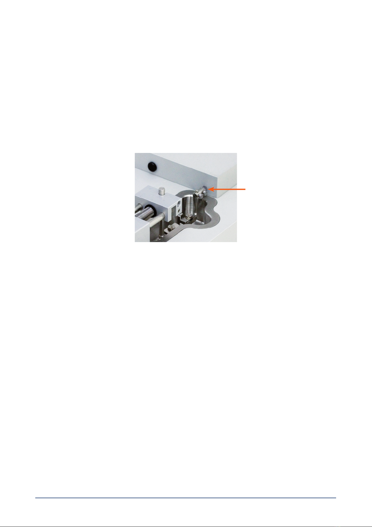
AFTER CLEANING, ALWAYS CHECK THAT THE GREASE AROUND THE TRANSDUCER PIN IS SUFFICIENT TO KEEP THE BUFFER
AND WATER FROM ENTERING THE TRANSDUCER HOUSING SEE FIGURE 3.1.
If red or brown discolorations appear on the chamber sides or on the supports, the following cleaning procedure will work in most
cases:
1. Incubate the chamber and supports for 30 minutes with 2mM T-1210 Tetrakis- (2-pyridylmethyl)-ethylenediamine solution
dissolved in double distilled water.
2. Use a cotton-tip applicator to mechanically clean all the affected surfaces during the last 15 minutes of the incubation period.
3. Wash the chamber and supports several times with double distilled water.
4. Incubate the chamber with 96% ethanol for 10 minutes while continuing the mechanical cleaning with a cotton-tip applicator.
5. Remove the ethanol solution and wash a few times with double distilled water. Incubate the chamber and supports with an
8% acetic acid solution for 10 minutes and continue the mechanical cleaning with a swab-stick.
6. Wash the chamber and supports several times with double distilled water.
7. Dry the surfaces using absorbent paper (i.e. Kim-Wipes) or cotton-tip applicators.
IMPORTANT NOTES
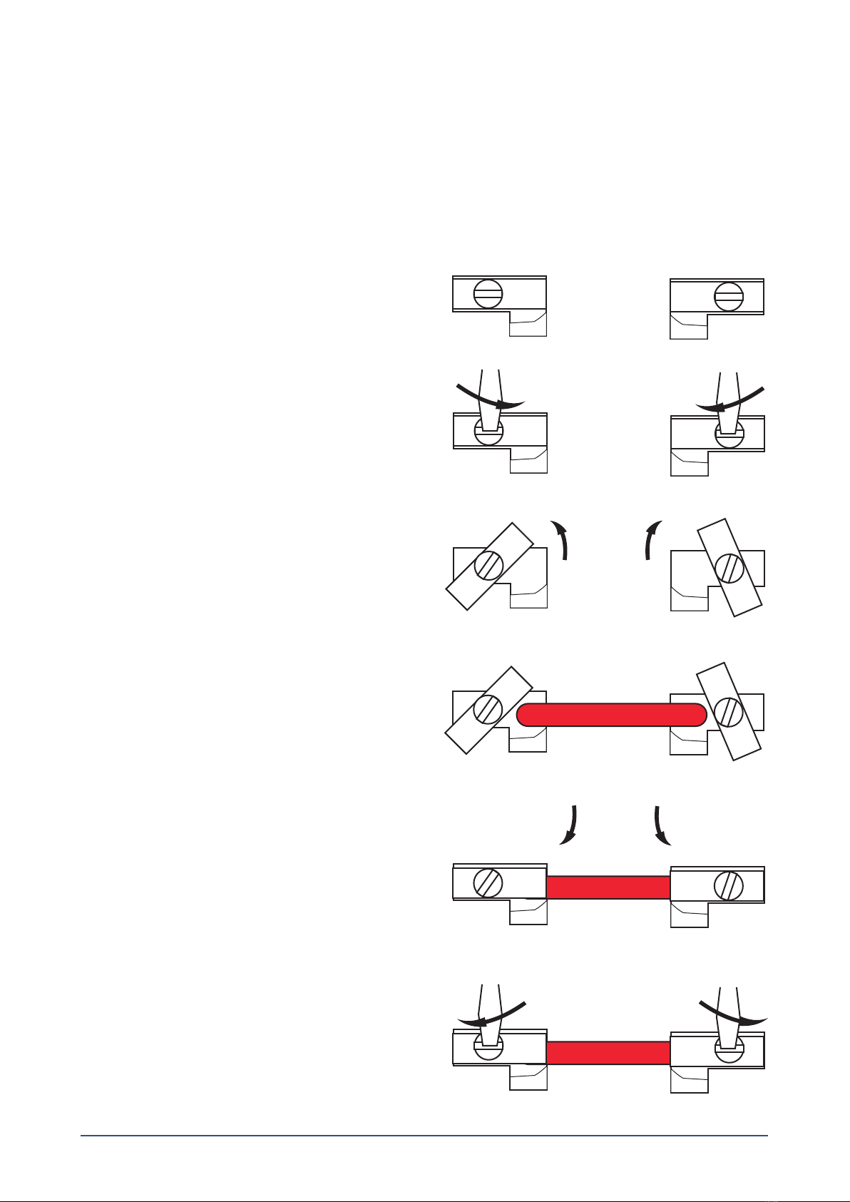
IN EXCEPTIONAL CASES, THE SUPPORTS CLAMP MAY NEED TO BE REMOVED FROM THE CHAMBER AND CLEANED
INDIVIDUALLY TO ASSURE PROPER CLEANING OF ALL SUPPORT SURFACES. NEVER SOAK THE SUPPORTS IN ANYTHING
STRONGER THAN 8% ACETIC ACID FOR EXTENDED PERIODS OF TIME I.E. SEVERAL HOURS OR OVERNIGHT!

10CHAPTER 4
3.2 Maintenance of the force transducer
The force transducer is the most delicate and fragile component of the Muscle Strip Myograph. Extreme care must be used when
handling or touching the force transducers.
As a part of daily maintenance, inspect the grease around the transducer pin extending from the transducer housing pinhole
(see gure 3.1) before starting any experiment. Insufcient grease in this area will allow buffer and water to enter the transducer
housing and cause damage to the force transducer.
IMPORTANT
DMT RECOMMENDS USE OF HIGH VACUUM GREASE ONCE A WEEK TO SEAL THE TRANSDUCER HOLE BY FRE QUENTLY USE.
DMT TAKES NO RESPONSIBILITIES FOR THE USE OF ANY OTHER KINDS OF HIGH VACUUM GREASE THAN THE ONE
PURCHASED FROM DMT.
DMT TAKES NO RESPONSIBILITIES FOR ANY KIND OF DAMAGE APPLIED TO THE FORCE TRANSDUCER.
3.2.1 Checking the force transducer
The Muscle Strip Myograph force transducer is a strain gauge connected to a Wheatstone bridge. The force transducers for each
chamber are housed in a separate, protective compartment (transducer house). Although the protective cover offers some me-
chanical protection for the force transducers, they are still very vulnerable to applied forces exceeding 1 Newton (100 grams) or
uid running into the transducer compartment due to insufcient greasing of the transducer pinhole, see gure 3.1.
If the force readings on the Multi Interface appear unstable or noisy, then rst check that the chambers are connected properly
to the Multi Interface and that the Muscle Strip Myographs are plugged all the way into the Multi Interface.
If the force reading(s) are still unstable or noisy, then perform a new calibration of the force transducer as described in chapter
3.5.1 in Multi Myograph System User Manual.
During the new calibration, monitor the relative force reading values in the FORCE CALIBRATION sub-menu on the Multi Interface
(Steps 4 and 5 of the calibration procedure):
• If the value is 0, a single digit, or above 6500, then the force transducer is broken and needs to be replaced.
If the message “OFF” is displayed on the main page of the Multi Interface even though the Muscle Strip Myographs is plugged in
at the rear of the Multi Interface, then the force transducer is broken and needs to be replaced. In addition, if the force reading(s)
appear yellow in color, cannot be reset to zero, AND the transducer cannot be recalibrated, then the force transducer is broken
and needs to be replaced.
If any other problems related to the force transducer are encountered, please contact DMT for advice or further instructions.
Figure 3.1 Close-up of transducer pin from outside.
The arrow indicates the place that the grease needs to be applied to prevent water and buffer from damaging the transducer.

11 MUSCLE STRIP MYOGRAPH SYSTEM - 820MS - USER MANUAL
4. The replacement transducer will be shipped with the new transducer inside a new transducer house.
5. Place a VERY small amount of vacuum grease (clear or whitish grease) around the bottom inside of the transducer hous-
ing to seal the transducer housing when put back in place. An arrow in gure 3.3 below indicates the place that the grease
needs to be applied
6. Carefully realign the transducer housing with the new transducer on the Muscle Strip Myograph and reinsert the Allen
screws through the bottom of the Muscle Strip Myograph.
7. Tighten the screws and place some vacuum grease from the outside around the transducer pin that protrudes from the
transducer housing. Make sure that the hole is completely sealed to prevent buffer solution or water from entering the
transducer housing and damaging the new force transducer. Arrow in gure 3.3 indicates the place that the grease needs
to be applied.
IMPORTANT
CALIBRATE THE NEW FORCE TRANSDUCER BEFORE PERFORMING A NEW EXPERIMENT!
Figure 3.3 The transducer in the transducer housing and close-up of transducer pin inside the transducer
The arrow indicates the place that the grease needs to be applied to prevent water and buffer from damaging the transducer.
3.2.2 Force Transducer Replacement
If the force transducer breaks and needs to be replaced, follow this step-by-step replacement procedure carefully:
1. Remove the clamp from the transducer pin coming out of the transducer house.
2. Disconnect the Muscle Strip Myograph from the Multi Interface.
3. Turn the Muscle Strip Myograph upside down and remove the transducer housing by loosening the two screws “A” + ”B” as
illustrated in gure 3.2 below.
Figure 3.2 - The 2 screws that secure the transducer house to the chamber
B
A

12CHAPTER 4
Figure 3.4 The areas where linear slide grease may be applied for smooth micropositioner movement
3.3 Maintenance of the micropositioner
Check the micropositioner for grease at least ONCE A WEEK. There are 3 main parts that will need to be greased on the mi-
cropositioner, those parts being the micropositioner screw thread and the 2 slide bars to the left and right of the micropositioner
screw thread. In case of insufcient lubrication, grease the micropositioner with the “Grease for Linear Slides” included with your
system. Apply the linear slide grease in the areas indicated by the arrows in gure 3.4 below.
Other manuals for 820MS
2
Table of contents
Other DMT Laboratory Equipment manuals
Popular Laboratory Equipment manuals by other brands

Coltene
Coltene SciCan STATIM 2000S Operator's manual

HTA
HTA HT2800T user guide

caron
caron 6540-1 Preventive Maintenance Instructions

Pasco Scientific
Pasco Scientific OS-8523 Instruction manual and experiment guide

VWR
VWR PCR Workstation instruction manual

Speakman
Speakman SE-925 Installation, Maintenance & Operation Instructions