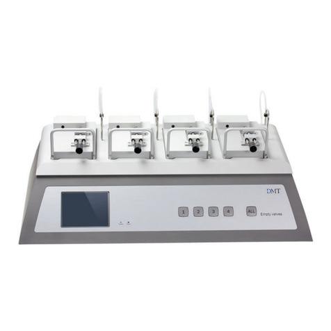
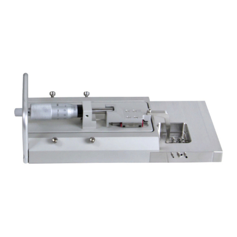
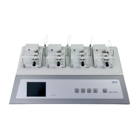
DMT 560TP User manual

USER MANUAL, VOL.2.0
TISSUE PULLER - 560TP

2
TISSUE PULLER 560TP
USER MANUAL

3TISSUE PULLER - MODEL 560TP - USER MANUAL
TISSUE PULLER
MODEL 560TP
TRADEMARKS
Danish Myo Technology A/S reserves the right to alter specications as required.
This document was, as far as possible, accurate at the time of printing.
Changes may have been made to the software and hardware it describes since then.
New information may be supplied separately.
This documentation is provided with the
Tissue Puller - 560TP
No part of this document may be reproduced by any means without the
prior written permission of Danish Myo Technology A/S.
Copyright © Danish Myo Technology A/S

4
CONTENTS
CONTENTS
Trademarks .......................................................................................................................................................................................................................................2
Safety ..................................................................................................................................................................................................................................................4
EC Declaration of Conformity ....................................................................................................................................................................................................4
Unpacking the Tissue Puller System........................................................................................................................................................................................5
Chapter 1 - System overview .....................................................................................................................................................................................................6
1.1 Tissue Puller - 560TP front and rear ................................................................................................................................................6
Chapter 2 - Setting up ..................................................................................................................................................................................................................7
2.1 The complete Tissue Puller System - 560TP ...................................................................................................................................7
2.2 Setting up step-by-step .....................................................................................................................................................................7
2.3 Conguration of the MyoPULL and 560TP System .........................................................................................................................8
2.4 Force Calibration ...............................................................................................................................................................................9
Chapter 3 - The MyoPULL Menus .......................................................................................................................................................................................... 11
3.1 MyoPULL Menu ............................................................................................................................................................................... 11
3.2 View Menu ...................................................................................................................................................................................... 12
3.3 Experimental setup ........................................................................................................................................................................ 12
Chapter 4 - Maintenance.......................................................................................................................................................................................................... 14
4.1 Checking the force transducer ..................................................................................................................................................... 14
4.2 Force Transducer Replacement .................................................................................................................................................... 15
4.3 Maintenance .................................................................................................................................................................................. 15
Appendix 1 - Reading a millimetre micrometer............................................................................................................................................................... 16
Appendix 2 - System specications ..................................................................................................................................................................................... 17

5TISSUE PULLER - MODEL 560TP - USER MANUAL
SAFETY
560TP has been designed for use only in teaching and research applications. It is not intended for clinical or critical life-care
use and should never be used for these purposes; nor for the prevention, diagnosis, curing, treatment, or alleviation of disease,
injury, or handicap.
• Do not open the unit: the internal electronics pose a risk of electric shock.
• Do not use this apparatus near water.
• To reduce the risk of re or electric shock, do not expose this apparatus to rain or moisture. Objects lled with liquids should
not be placed on the apparatus.
• Do not block any ventilation openings. Install in accordance with the manufacturer’s instructions.
• Only use secure industry standard connectors and tubing for pressure connections. Faults, defects and mistakes due to
wrong connections void warranty. We are not liable for errors and mistakes due to inappropriate pressure connection.
• Do not install near any heat sources such as radiators, heat registers, stoves, or any other apparatus that produces heat.
• Only use attachments and accessories specied by the manufacturer.
• Unplug this apparatus during lightning storms or when unused for long periods of time.
The 560TP is delivered with an external 100-240V AC to 24V DC ADAPTER. Protect the power ADAPTER and cord from being
walked on or pinched. Particularly at power plugs and at the point where they connect to the apparatus.
Refer all servicing to qualied service personnel. Servicing is required when the apparatus has been damaged in any way,
including: the power-supply cord or plug being damaged, liquid spilling onto or objects falling into the apparatus, exposure to rain
or moisture, abnormal operation, or the unit being dropped.
EC DECLARATION OF CONFORMITY
Danish Myo Technology A/S
Certify and declare that the following apparatus:
Tissue Puller 560TP
Restrictive use: Only for laboratory use.
Manufactured by:
Danish Myo Technology A/S
Skejbyparken 152
8200 Aarhus N.
Denmark
Conforms with the essential requirements of the EMC Directive 2004/108/EC.
Based on the following specications applied by:
EN 61326-1:2006
EN 61326-2-6:2006
EN 61326-2-6/Corr.:2007
And with the LVD Directive 2006/95/EC.
Based on the following specications applied by:
EN 61010-1:2010
EN 61010-2-030:2010
General warnings regarding EMC:
Do not use this device in close proximity to sources of strong electromagnetic radiation (e.g. unshielded intentional RF sources),
as these may interfere with the proper operation.

6UNPACKING THE TISSUE PULLER SYSTEM
UNPACKING THE TISSUE PULLER SYSTEM
Take a few minutes to carefully inspect your new Tissue Puller System - 560TP for damage which may have occurred during
handling and shipping. If you suspect any kind of damage, please contact DMT immediately and the matter will be pursued
as soon as possible. If the packing material appears damaged, please retain it until a possible claim has been settled. We
recommend that you store the packing material for any future transport of the 560TP System. In case of transport and the
original packing material is unavailable, please contact DMT Sales Department for advice and packing instructions.
After unpacking your new 560TP System, please use the following list to check that the system is complete:
• 1 Tissue Puller - 560TP System unit (electromechanical)
• 1 USB cable
• 1 power cord* (24V Powerconverter)
• 1 box with mounting hook or other customer dened mounting supports
• 1 calibration weight 5g weight
• 1 Allen key
• 1 CD with MyoPULL Software (Windows 7)
• 1 CD with User Manual
* The shape of the AC plug varies by country; be sure that the plug ts the outlets for your location.

7TISSUE PULLER - MODEL 560TP - USER MANUAL
CHAPTER 1 SYSTEM OVERVIEW
1.1 Tissue Puller - 560TP front and rear
Figure 1.1 Tissue Puller - 560TP front
Figure 1.2 Tissue Puller - 560TP back rear
USB port
ON/OFF switch
Power inlet - 24VDC 0,75A (V+ on center pin)
Micrometer
Motor
Force transducer
Force transducer hook
Jaws
Power ON indicator

8CHAPTER 2
CHAPTER 2 SETTING UP
2.1 The complete Tissue Puller System - 560TP
Figure 2.1 Set-up for the Tissue Puller with MyoPULL Data Acquisition Software
Data Acquisition Software - MyoPULLTissue Puller 560TP
2.2 Setting up step-by-step
To set up the 560TP System as illustrated in gure 2.1:
1. Connect the 560TP to the PC with the supplied USB cable.
2. Follow the supplied Quick Installation Guide for MyoPULL.
3. Connect the supplied 24V power converter to the 560TP.
4. Turn on the power to the 560TP.
5. Start the MyoPULL software on the PC.
The following MyoPULL screen should now be visible on the screen:
Figure 2.2 MyoPULL Software

9TISSUE PULLER - MODEL 560TP - USER MANUAL
2.3 Conguration of the MyoPULL and 560TP System
On the right hand side of the MyoPULL window the 560TP Puller controller window is shown.
The 560TP Puller controller window has the following functions:
• Position - This is used to enter the position the micrometer positioner should
move to when clicking the ‘Move’ button. Enter the position in micrometers and
hit the ‘Enter’ key on the key board.
• Move - Activating this function will cause the micrometer positioner to move to
the position set in the ‘Position’ eld.
• Reset Position - Used to synchronize the 560TP micrometer positoner and the
MyoPULL program.
IMPORTANT
ALWAYS SYNCHRONIZE MICRO POSITIONER AND MyoPULL BEFORE START
ING AN EXPERIMENT.
• Arrow up and down - Manually move the micrometer positioner up or down by
clicking the Arrow Up or Arrow Down button, respectively.
• Current Force - This box will always show the current force of the force trans-
ducer.
• Zero force - Zero the force transducer.
• Calibrate Force - Force calibrate the force transducer (see chapter 2.4).
Figure 2.3 MyoPULL Software - Puller controller at the far right
Figure 2.4 Puller Controller close-up
The 560TP will not remember the position of the micrometer after the MyoPULL software has been closed and the 560TP has
been turned off. Therefore it is vital to synchronize the 560TP and the MyoPULL software by clicking the ‘Reset Position’ button
on the far right in the MyoPULL window. A box will appear on the screen and here the actual position of the micrometer should
be entered, see gure 2.5 (see Appendix 1 - Reading a millimetre micrometer). Carefully read the position of the micrometer on
the 560TP and enter the value in the ‘Reset Position’ box and hit enter. The actual position of the micrometer is now entered in
the MyoPULL software and it will store this position until the MyoPULL software is closed or the power of the 560TP is turned off.
NOTE
RESETTING OF MICROMETER POSITION IS VERY IMPORTANT BEFORE STARTING AN EXPERIMENT.

10
Figure 2.4 Puller Controller close-up
CHAPTER 2
Figure 2.5 ‘Current position’ box
2.4 Force Calibration
Before the 560TP is packed and shipped it has gone through two days of continuous testing, including a nal force transducer
calibration. However, DMT recommends that a force transducer calibration is performed before using the 560TP System for the
rst time. The force transducer calibration is described in the following section.
1. Click on the ‘Calibrate Force’ button on the right hand side of the MyoPULL software window (see gure 2.5).
2. Read the calibrate information on the screen carefully. Please note that even very small vibrations or slight instability of
mounting supports will affect the calibration.
3. Zero the force by clicking the ‘Zero Force’ button (see gure 2.6). The force transducer is now zeroed.
4. Press ‘Next’.
Figure 2.6 ‘Zero Force’ button and ‘Next’ button

11 TISSUE PULLER - MODEL 560TP - USER MANUAL
5. Read the new ‘Calibrate Menu’ box carefully.
6. Carefully place the supplied 5 g weight or another precise weight on the mounting device attached to the force transducer.
7. Wait until the weight on the force transducer mounting support is no longer moving. This is very Important. Please note that
even very small vibrations or slight instability of mounting supports will affect the calibration.
8. Enter the corresponding force (see gure 2.7) in mN of the weight placed on the force transducer. 1 gram equals 9,81mN
and therefore a 5 g weight is 5x 9,81mN = 49,05mN
9. Press the ‘Set Force’ button and the 560TP force transducer has now been calibrated.
10. To complete and store the calibration press ‘Finish’.
The 560TP System is now ready for an experiment.
Figure 2.7 ‘Set force’ button

12
CHAPTER 3 THE MYOPULL MENUS
The 560TP is operated via the MyoPULL software. The function of the software is to record force/displacement curves of tensile
strength tests with a force between 0 – 3000 mN over a displacement distance of 0 – 50000 µm, with speeds of 1 – 150 µm/
sec.
In the MyoPULL program there are two main menus: the MyoPULL menu and the View menu.
3.1 MyoPULL Menu
In the MyoPULL menu there are four sub-menus, the Pull, Start Position, Selection and Stress - Strain Preset menu.
Figure 3.1 MyoPULL menu
CHAPTER 3
Pull sub-menu:
• Target Velocity - setting of the velocity of the motor in µm/second.
• Pull Range - Setting of the distance the motor will pull from the given start point.
• Start Pull and Stop Pull - Clicking these buttons will either start the motor or stop it.
Start Position sub menu:
• Start Position - Enter the start position of the motor in µm.
• Move to Start Position - Activating this button will move the micrometer to the position entered in the Start Position.
Selection sub menu:
• Add Selected Range - Select a part of the curve of interest by dragging the mouse across the curve. The maximum force,
stress and distance of the selected part of a Pull-curve is transferred to the Experiments window by clicking the Add Select-
ed Range button. The selected part will be shown on the screen. To return to the original Pull experiment simply double-click
on the appropriate Pull in the Experiments list.
Strain - Stress presets: MyoPULL needs information on the mounted segment length, thickness and diameter to be able to cal-
culate and draw a Stress - Strain Graph.
• Segments Length – Enter the length of the mounted segment in µm.
• Segment Thickness – Enter the thickness of the mounted segment in µm.
• Segment Diameter – Enter the diameter of the mounted segment in µm.

13 TISSUE PULLER - MODEL 560TP - USER MANUAL
3.2 View Menu
In the View menu there are two sub-menus: the View and Graph Type sub-menu.
View sub-menu:
• Show Puller 560 Control Panel - Show or hide 560TP control panel.
• Show Experiment List Panel - Show or hide the Experiment List containing all the experiments performed.
Graph Type sub-menu:
• Selection of the Graph Type - MyoPULL can display the experiment as Displacement-Force Graphs or Strain - Stress Graphs.
In Displacement-Force Graphs the x-axis is shown in µm and the Y-axis in mN. In the Strain - Stress Graphs the X-axis is
Strain and the Y-axis is Stress (mN/mm2).
3.3 Experimental setup
The 560TP is a system specically designed to perform tensile strength tests.
1. Mount the sample you wish to test tensile strength for between the motor (via the force transducer) and the jaw.
2. Enter the µm the tissue is to be stretched in Pull Range.
3. Enter the velocity (0-150µm/sec) the motor is to use during the stretch in Target Velocity.
4. If you want to repeat a stretch enter the micro-positioner position in the Start Position box and press Enter.
5. If you want to display the experiment as a Stress - Strain Graph enter the values for segments length, segment thickness
and segment diameter, all in µm.
6. Select how the experiment should be displayed; either as a Force-Displacement Graph or a Stress - Strain Graph.
7. To start the Pull experiment press Start Pull. The force that the sample is exposed to and the motor’s present position is
plotted by the MyoPULL software, thereby creating a Force-Displacement Curve as seen in gure 3.3 on next page or as a
Stress - Strain Curve as shown in gure 3.4 on next page.
8. After a completed Pull experiment MyoPULL automatically transfers the maximum force or stress value to the Experiment
List where the Micrometer Position, Max Force and Max Stress will be recorded.
Figure 3.2 View menu

14
CHAPTER 3
Figure 3.3 Example of a Tensile Strength Test Curve.
The force (mN)readings are shown on the Y-axis and the displacement in µm is shown on the X-axis
Figure 3.4 Example of a Stress - Strain Test Curve.
The stress (YY) readings are shown on the Y-axis and the strain in mN/mm2 is shown on the X-axis.

15 TISSUE PULLER - MODEL 560TP - USER MANUAL
CHAPTER 4 MAINTENANCE
4.1 Checking the force transducer
The 560TP force transducer is a strain gauge connected to a Wheatstone bridge. The force transducer is housed in a separate,
protective compartment (see gure 4.1 below). While the protective cover offers some mechanical protection for the force trans-
ducers, it is still very vulnerable to applied forces exceeding 1 Newton (100 grams) or uid running into the transducer compart-
ment due to inadequate greasing of the transducer pinhole (see chapter 4.3 Maintenance). If the force readings in MyoPULL ap-
pear unstable or noisy, then perform a new calibration of the force transducer as described in chapter 2.4. During the calibration
monitor the relative force reading values in the FORCE CALIBRATION sub-menu in the MyoPULL Software. The normal operating
values for the force transducer during calibration should be between 3000 and 3500.
• If the value is 0, a single digit, or a three digit number, the force transducer is broken and needs to be replaced.
• If the value is less than 2000 or greater than 4500, the force transducer is broken and needs to be replaced.
In addition, if the force reading cannot be reset to zero AND the transducer cannot be recalibrated, the force transducer is broken
and needs to be replaced. If any other problems related to the force transducer are encountered, please contact DMT for advice
or further instructions.
Figure 4.1 Illustration of the transducer compartment

16
4.2 Force Transducer Replacement
If the force transducer breaks and needs to be replaced the 560TP need to be shipped back to DMT for replacement. The ship-
ping address is:
Danish Myo Technology A/S
Skejby Science Center
Skejbyparken 152
DK-8200 Aarhus N.
Denmark
Tel: +45 8741 1100
Please contact your Sales Representative and request a Return to Manufacturer Authorisation (RMA) Number to attach to your
shipping documentation.
4.3 Maintenance
The 560TP is a very delicate and sophisticated piece of research equipment. DMT recommends that the following sections are
read carefully and that the instructions are followed at all times.
Force transducer: The force transducer is the most delicate and fragile component of the 560TP. Extreme care must be used
when handling or touching the force transducer. As part of daily maintenance, inspect the grease around the transducer pin ex-
tending from the transducer compartment pinhole before starting any experiment. Insufcient grease in this area will allow buffer
and water to enter the transducer compartment and cause irreparable damage to the force transducer.
IMPORTANT NOTES
• DMT RECOMMENDS THAT THE HIGH VACUUM GREASE SEALING THE TRANSDUCER PINHOLE IS CHECKED AND RE
PLACED AT LEAST ONCE A WEEK, ESPECIALLY IF THE MYOGRAPH IS USED FREQUENTLY
• DMT TAKES NO RESPONSIBILITY FOR THE USE OF ANY OTHER KIND OF GREASE OTHER THAN THE GREASE SUPPLIED
BY DMT FOR THIS PURPOSE
• DMT TAKES NO RESPONSIBILITY FOR ANY KIND OF DAMAGE CAUSED BY MISHANDLING OF THE FORCE TRANSDUCERS
CHAPTER 4

17 TISSUE PULLER - MODEL 560TP - USER MANUAL
APPENDIX 1 READING A MILLIMETRE MICROMETER
Sleeve scale
The micrometer sleeve scale has a total length of 25 mm divided into fty equal parts. Each part of division above the horizontal
line represents 1 mm where each fth line is marked by a longer line and a number, which designates the length in mm. Each part
of division below the horizontal line is placed between each 1 mm mark (scale above the horizontal line) and represents 0.5 mm.
Thimble scale
The thimble is divided into fty equal parts, and one complete rotation of the thimble is indicated by the smallest division on the
sleeve, which equals 0.5 mm. Each divi¬son on the thimble scale is 10 μm. If the thimble scale falls between two lines, then a
number between 0 and 10 μm must be approximated.
Example 1
1. Note that the thimble has stopped at a point beyond “10” on the sleeve indicating 10000 µm (10 mm).
2. Note that there is no mark completely visible between the 10 mm mark and the thimble.
3. Read the value on the thimble corresponding to the intersection with the horizontal line on the sleeve.
A. Reading on sleeve:
B. No additional mark visible:
C. Thimble reading:
Total reading:
Example 2
1. Note that the thimble has stopped at a point beyond “16” on the sleeve indicating 16000 µm (16 mm).
2. Note that this time a mark is visible between the 16 mm mark and the thimble indication 500 µm.
3. Read the value on the thimble corresponding to the intersection with the horizontal line on the sleeve.
A. Reading on sleeve:
B. One additional mark visible:
C. Thimble reading:
Total reading:
Figure A1.1 Overview of the micrometer parts (actual reading 20000 µm = 20 mm)
Sleeve scale Thimble scale
Figure A1.2 Example 1:
reading = 10380 µm
10000 µm
0 µm
380 µm
10380 µm
Figure A1.3 Example 2:
reading = 16780 µm
16000 µm
500 µm
280 µm
16780 µm

18APPENDIX 2
APPENDIX 2 SYSTEM SPECIFICATIONS
Technical specications
Vessel size/tissue length: >500 μm – 20 mm
Force range: 0 – 2N (0 – 2000 mN or ~ 204 g)
Tare range: 0 – 1N (0 – 1000 mN or ~ 104 g)
Force resolution: 1 mN (~ 0.1 g)
Displacement range: 0 – 50 mm (5 cm or 50,000 μm)
Displacement resolution: 1 μm
Max displacement speed: 150 μm/second (~9 mm/minute)
Weight calibration: Semi-automatic (via software)
Data communication: USB (2.0)
Voltage: 100 to 240 VAC (auto) 50/60 Hz via external power supply
Data Acquisition software: MyoPULL software - Requirements:
Windows 7 (32- and 64-bit)
Optional accessories
Mounting supports: Different mounting support available
Other manuals for 560TP
1
Table of contents
Other DMT Laboratory Equipment manuals
Popular Laboratory Equipment manuals by other brands

Dosmatic
Dosmatic Advantage A20-10% Installation & operating instructions

WPI
WPI PV850 instruction manual

Centurion Scientific
Centurion Scientific PrO-Hospital Ambient instruction manual

Holland Green Science
Holland Green Science Ygrasia 10813001 user manual

TESTING
TESTING 1.0206.07 operating instructions

Forma Scientific
Forma Scientific 1284 instruction manual