DMT 620M User manual

USER GUIDE, VOL.2.0
WIRE MYOGRAPH SYSTEM - 620M

User Guide
Version 1.0
WIRE MYOGRAPH 620M
USER GUIDE

3
CONTENTS
Chapter 1 - Wire Myograph overview .................................................................................................................................................................................... 3
Chapter 2 - setting up the wire myograph - 620M............................................................................................................................................................ 4
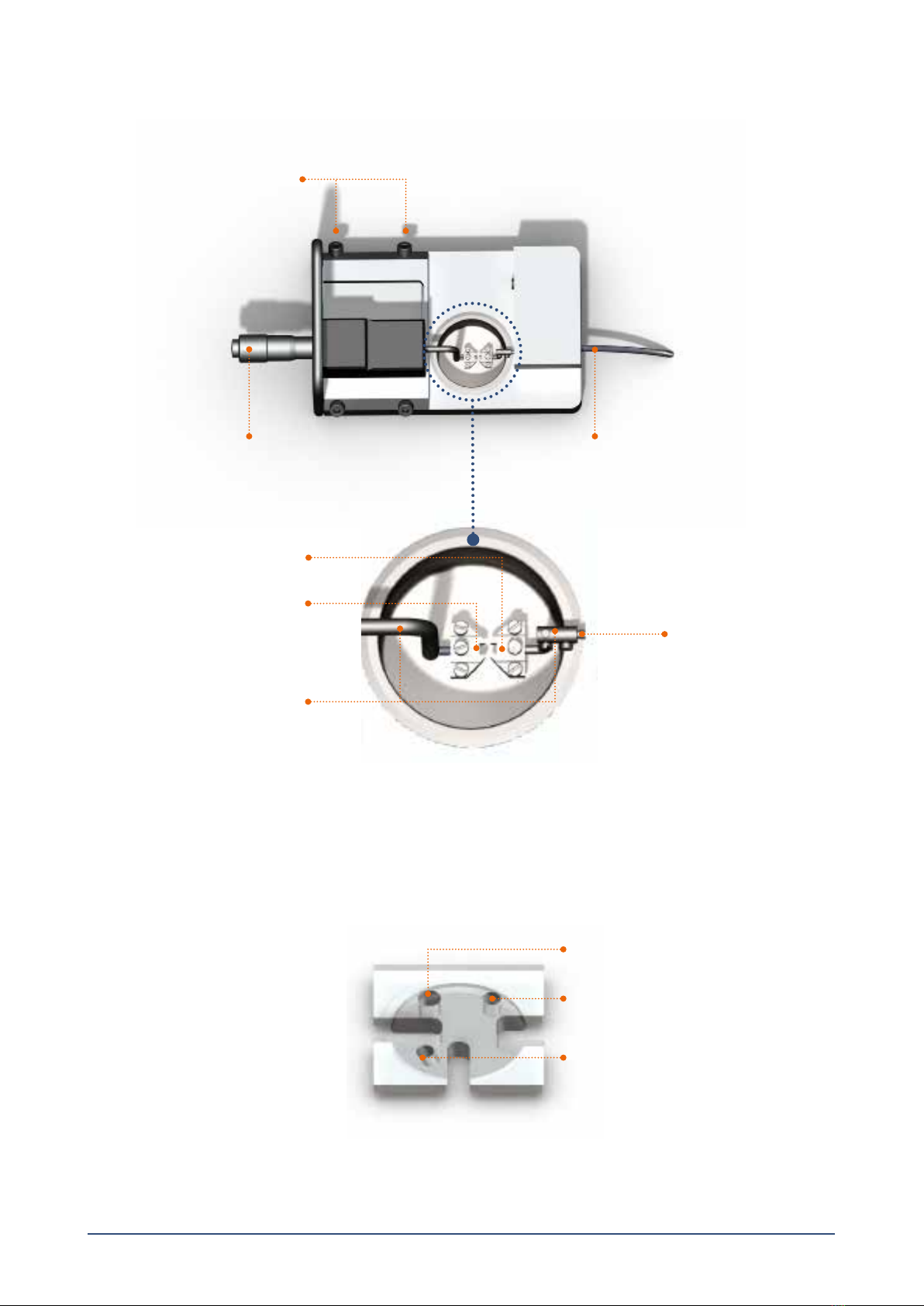
2.1 Changing and adjusting the mounting supports ...................................................................................................................................................... 4
2.1.1 Changing the mounting supports (gure 2.1)......................................................................................................................................................... 4
2.1.2 Coarse adjusting the jaws for small vessels (gure 2.1)........................................................................................................................................ 4
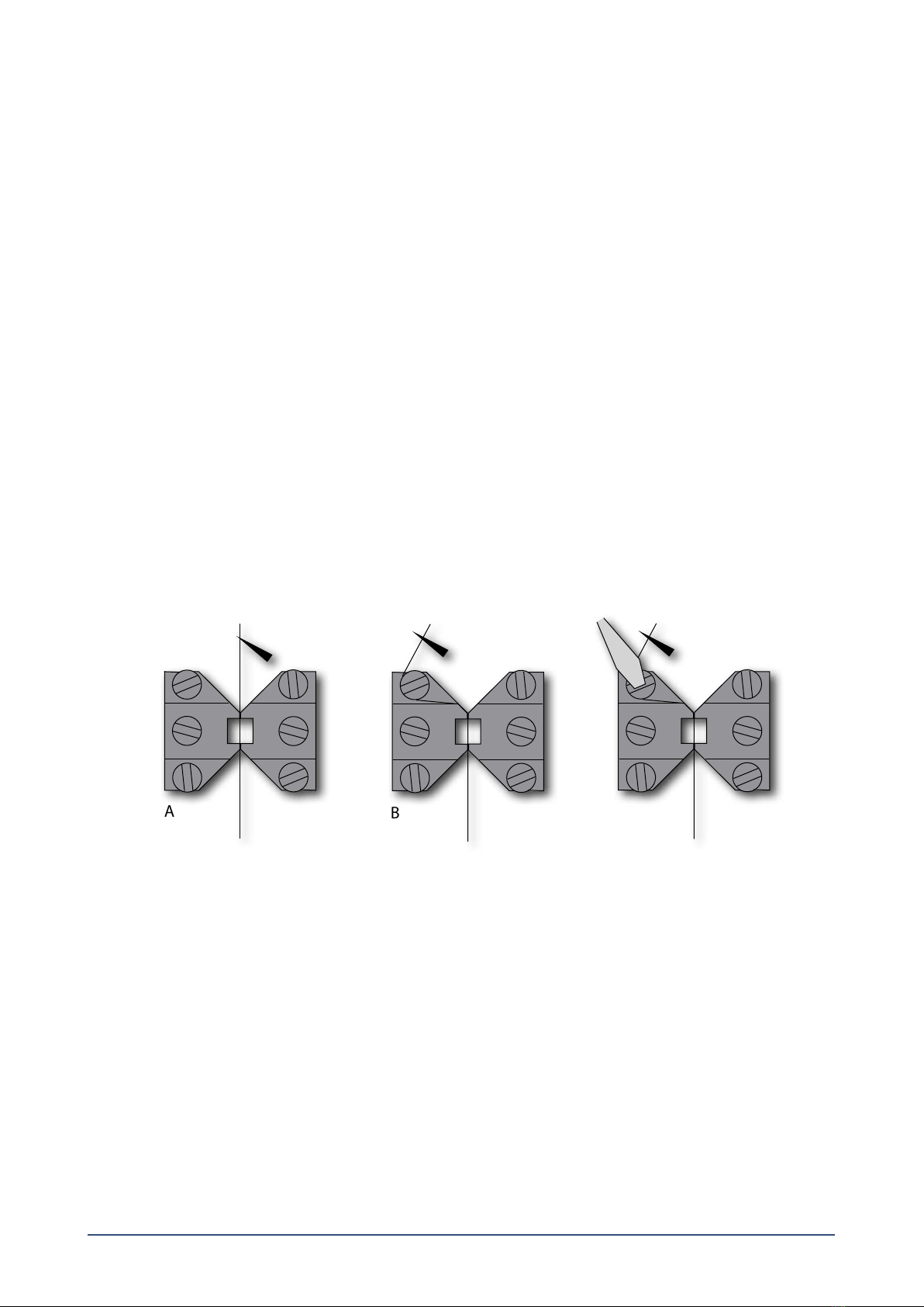
2.1.3 Fine adjusting the jaws for small vessels (gure 2.2 and gure 2.3)................................................................................................................. 5
2.1.4 Fine adjusting the pins for larger vessels (gure 2.4 and gure 2.5):............................................................................................................... 6
2.2 Calibration of the force transducer.................................................................................................................................................................................. 6
Chapter 3 - Experimental set-up ............................................................................................................................................................................................. 7
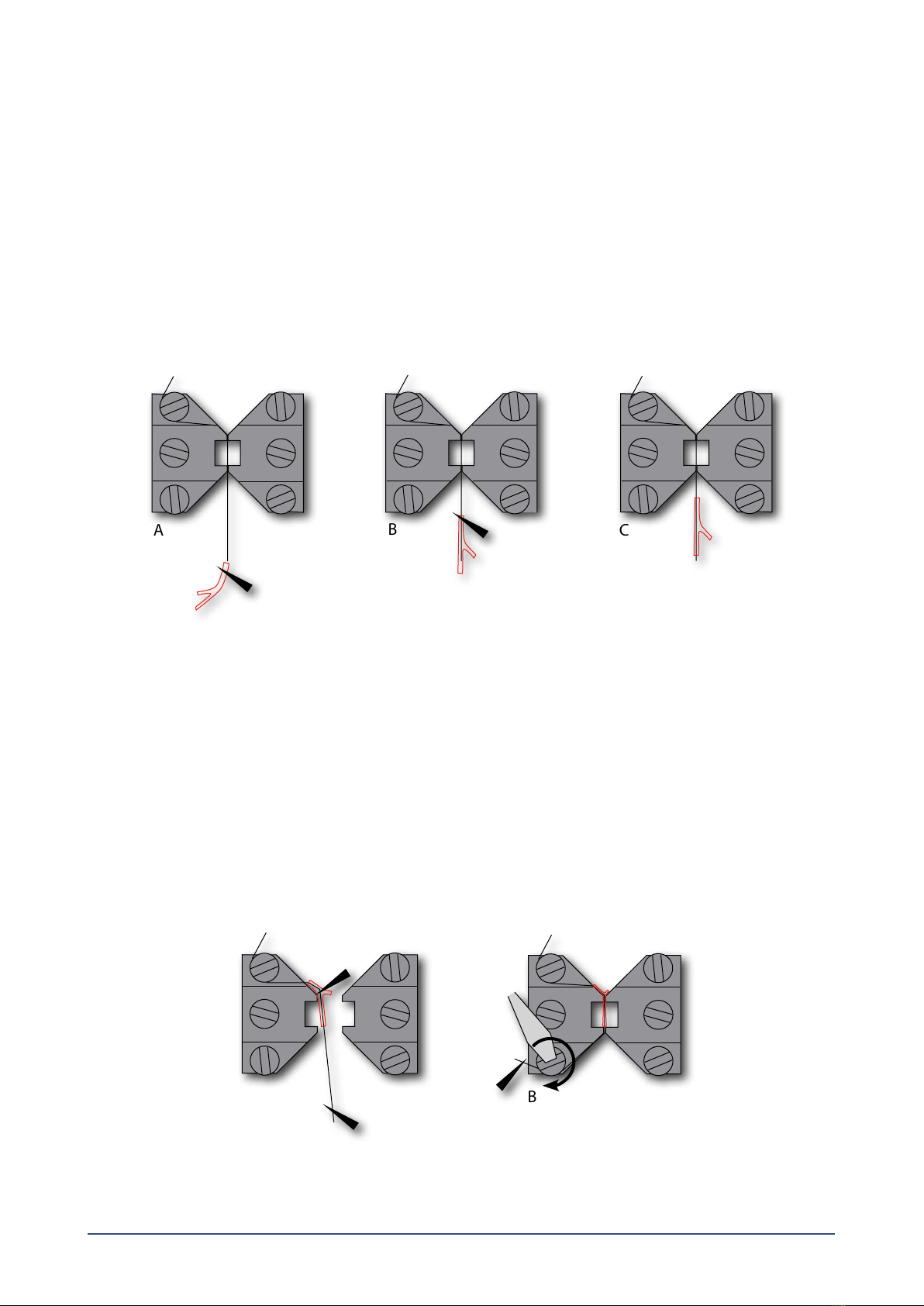
3.1 Mounting protocol for small arteries .............................................................................................................................................................................. 7
3.1.1 Mounting step one............................................................................................................................................................................................................. 7
3.1.2 Mounting step two............................................................................................................................................................................................................. 8
3.1.3 Mounting step three.......................................................................................................................................................................................................... 8
3.1.4 Mounting step four............................................................................................................................................................................................................ 9
3.1.5 Mounting step ve............................................................................................................................................................................................................. 9
3.1.6 Mounting step six.............................................................................................................................................................................................................10
3.1.7 Mounting step seven.......................................................................................................................................................................................................10
3.2 Normalization........................................................................................................................................................................................................................10
3.2.1 Principles of the normalization procedure..............................................................................................................................................................11
3.3 Standard start ........................................................................................................................................................................................................................11
3.3.1 Principles of the standard start procedure..............................................................................................................................................................11
3.4 Endothelium function ........................................................................................................................................................................................................12
3.4.1 Principles of checking endothelium function........................................................................................................................................................12
3.5 In vitro experiment 1: Noradrenaline contractile response..................................................................................................................................13
3.5.1 Background.........................................................................................................................................................................................................................13
3.5.2 Protocol ................................................................................................................................................................................................................................13
3.6 In vitro experiment 2: Acetylcholine relaxation curve............................................................................................................................................14
3.6.1 Background.........................................................................................................................................................................................................................14
3.6.2 Protocol ................................................................................................................................................................................................................................14
Chapter 4 - Cleaning and maintenance ..............................................................................................................................................................................15
4.1 Cleaning the Wire Myograph ..........................................................................................................................................................................................15
4.2 Maintenance of the force transducer............................................................................................................................................................................16
4.2.1 Checking the force transducer.....................................................................................................................................................................................16
4.2.2 Force Transducer Replacement....................................................................................................................................................................................17
4.3 Maintenance of the linear slides.....................................................................................................................................................................................18
Appendix 1 - Buer recipes .....................................................................................................................................................................................................19
Appendix 2 - Normalization theory ......................................................................................................................................................................................21
Appendix 3 - Reading a millimetre micrometer...............................................................................................................................................................23

4WIRE MYOGRAPH SYSTEM - 620M - USER GUIDE
Connection to Interface
Allen screws for ne alignment
of the Wire Myograph jaws
Micrometer
Jaw connected
to Micrometer
Jaw connected
to force transducer
Force transducer pin
Supports
Figure 1.1 Wire Myograph with close-up of chamber
CHAPTER 1
Figure 1.2 Chamber cover
Access for drug application
Access or funnel
Access for temperature probe
CHAPTER 1 WIRE MYOGRAPH OVERVIEW

5
CHAPTER 2 SETTING UP THE WIRE MYOGRAPH 620M
2.1 Changing and adjusting the mounting supports
Each chamber can accommodate mounting supports for either small vessels (>50µm) or larger segments (>500µm).The mount-
ing supports can be changed easily and experiments can be performed with dierent vessels of varying internal diameter.
Continuous use and repeated greasing of the transducer arm holes will cause some misalignment of the mounting supports.
Therefore whether it is mounting supports for jaws or for pins they will need occasional adjustments. Changing and adjustment
of the mounting supports is performed using the following step-by-step procedure.
OBS
THE TRANSDUCERS ARE FRAGILE AND SENSITIVE TO MECHANICAL STRAIN. BE VERY CAREFUL WHEN CHANGING OR AD-
JUSTING THE MOUNTING SUPPORTS!
2.1.1 Changing the mounting supports (gure 2.1)
1. Use the micrometer to separate the supports as far apart as possible.
2. Use the small screwdriver provided to gently loosen screw “D” on the support attached on the transducer side using the
small screwdriver. Screw“D” is the screw on the transducer-side support closest to the transducer.
3. Gently pull the support away from the transducer pin.
4. Loosen screw“B” on the micrometer side with the appropriate tting Allen key.
5. Pull the support away.
NOTE
NUMBER THE SUPPORTS WITH THE NUMBER OF THE CHAMBER THEY WERE REMOVED FROM USING SOME KIND OF
PERMANENT MARKER. STORE THE SUPPORTS IN THE PROVIDED PLASTIC CASE. NUMBERING THE SUPPORTS WILL SAVE
TIME WHEN THE SUPPORTS ARE CHANGED AGAIN, LIMITING THE AMOUNT OF ADJUSTMENTS NEEDED AFTER EACH CHANGE.
2.1.2 Coarse adjusting the jaws for small vessels (gure 2.1)
1. Loosen screw“A” to move the micrometer side jaw toward or away from the micrometer.
6. Loosen screw“D” to move transducer-side jaw toward or away from the transducer.
3. Loosen screw ”C” to vertically alight the transducer side jaw. Screw ”C” is the screw on the transducer side support that is
furthest away from the transducer.
A B C D
Figure 2.1 Illustration of the screws for changing supports and coarse adjustment of the jaws
Micrometer
Transducer

6WIRE MYOGRAPH SYSTEM - 620M - USER GUIDE
2.1.3 Fine adjusting the jaws for small vessels (gure 2.2 and gure 2.3)
1. Tightening Screw“D” will move the micrometer side jaw downward and to the left.
2. Tightening both screws “D” and“B”will move the micrometer side jaw straight down.
3. Tightening both screws “C” and “A” will move the micrometer side jaw straight up.
CHAPTER 2
Figure 2.2 Fine adjustments of the jaws in the Wire Myograph chamber
Figure 2.3 - Illustrations of properly aligned jaws (depicted on the far left) and incorrectly aligned jaws
(depicted in the middle and far right).
A B
C D
Jaws from top view
Jaws from side view

7
2.1.4 Fine adjusting the pins for larger vessels (gure 2.4 and gure 2.5):
1. Loosen screw“A” to move the micrometer side arm holder sideways
2. Loosen screw ”B”to move the micrometer side pin toward or away from the transducer.
3. Loosen screw ”C” to align the transducer side pin horizontally.
4. Loosen screws ”D” and ”E” to align the heights of the pins vertically.
Figure 2.4 - Fine adjustments of the pins in the Myograph chamber
A B E D C
Pins from top view
Pins from side view
Figure 2.5 - Illustrations of properly aligned pins (depicted on the far left) and incorrectly
aligned pins (depicted in the middle and far right).
2.2 Calibration of the force transducer
As a part of the general maintenance of the Wire Myograph , DMT recommends that the Wire Myograph is force calibrated at
least once a month. The Wire Myograph should also be force calibrated every time the interface has been moved. Although lab
benches are all supposedly perfectly horizontal, small dierences in lab bench pitch can aect the calibration of the system.
The Wire Myograph should also be calibrated if the system has been idle for longer than a month. A step-by-step procedure is

8WIRE MYOGRAPH SYSTEM - 620M - USER GUIDE
CHAPTER 3 EXPERIMENTAL SETUP
This chapter contains experimental set-up for the Wire Myograph. For dissection of a vessel, please see Procedures for investi-
gations of small vessels using a small vessel Myograph by M.J. Mulvany.
3.1 Mounting protocol for small arteries
The procedure involves attaching the mounting wires to jaws which are in turn mounted on the force transducer. This force trans-
ducer is capable of measuring with a sensitivity of about 0.01 mN (1 mg), but can be damaged if the applied force exceeds about
1 N (100 g). Therefore care must be taken to avoid pressing the jaws too hard together. A movement of ~20 µm after they have
touched is sufficient to hold the wires clamped.
3.1.1 Mounting step one
• Cut lengths of 40 m wire ~2.2 cm long. Mount one wire on left-hand jaw of the Wire Myograph as follows.
• Holding wire at far end, place centre of wire between jaws and screw jaws together so that the wire is clamped (gure 3.1 A).
NOTE
DO NOT CLOSE THE JAWS TOO HARD AGAINST EACH OTHER.
• Bend the far end of the wire towards the left, and wrap it around under xing screw, so the wire is wound clockwise: tighten-
ing the screw will then tighten the wire. This procedure should result in the wire being clamped between the jaws and with
near end of wire pointing towards operator (gure 3.1 B-C).
• Fill the Wire Myograph chamber with PSS (at room temperature). See appendix 1 for example of buer recipes.
Figure 3.1 A, B and C Mounting step 1
ABC
CHAPTER 3

9
3.1.2 Mounting step two
• Using forceps to hold the handle segment, transfer excised vessel from Petri dish to the Auto Dual Wire Myograph chamber.
Hold the vessel as close to the proximal end as possible and try to mount the vessel onto the wire.
• If the lumen is shut, try one of the following possibilities:
1. Use the wire to gently push the lumen open (blood streaming out is a good sign).
2. Hold excised vessel about 3 mm from the cut end with one set of forceps and use the other forceps to squeeze the blood
remaining in lumen out through the cut end.
• Pull the proximal end of the excised vessel segment along the wire such that the vessel segment acts as its own feeder to be
feed into the wire into the vessel (gure 3.2 A-C). Be careful not to stretch the vessel segment if the end of the wire catches
the vessel wall.
3.1.3 Mounting step three
• Once the vessel segment is threaded onto the wire, catch the free end of the wire (nearest you) with the forceps and move
the jaws apart.
• While controlling the movement of the wire with the forceps, use the other forceps to gently pull the vessel segment along
the wire until the area of interest is situated in the gap between the jaws. The near end of the vessel segment shall lie about
0.1 mm inside the jaw gap to insure no point of contact (gure 3.3 A).
• Still controlling the free wire end with the forceps, move the jaws together to clamp the wire and in one movement secure
the wire under the near xing screw on the left-hand jaw. Again in a clockwise direction so that tightening the screw also
tightens the wire (gure 3.3 B).
Figure 3.3 A and B Mounting step 3
ABC
B
Figure 3.2 A, B and C Mounting step 2

10 WIRE MYOGRAPH SYSTEM - 620M - USER GUIDE
Figure 3.5 A, B and C Mounting step 5
ABC
ABC
Figure 3.4 A, B and C Mounting step 4
3.1.5 Mounting step ve
• Move the jaws apart (gure 3.5 A). Take a second wire holding it about one third down from the far end using a forceps.
Align the wire parallel with the vessel segment such that the wire can be passed into the far end of the lumen. Gently feed
the wire through the lumen of the vessel segment in one movement using the rst mounted wire as a guide (gure 3.5 B-C).
Hold the wire at a point at least 10 mm from the vessel to prevent the vessel being stretched during the manoeuvre. Be
careful not to touch the lumen of the vessel with the end of the wire and when pushing the wire end through the near end
of the lumen. Once the wire has successfully passed through the lumen of the vessel segment, place the wire in a position,
which ensures sucient length for the wire to be secured both at the near and far xing screws on the right-hand jaw.
3.1.4 Mounting step four
•Using forceps, gently rub the vessel segment on the far side of the jaw to separate any excess vessel segment from the area
of interest clamped in the gap between the jaws (gure 3.4 A). Make sure that the vessel segment is separated as close as
possible to the jaws (gure 3.4 B). The excessive vessel segment is nally dissected free and removed from the wire (gure
3.4 C).
CHAPTER 3

11
3.1.6 Mounting step six
• Carefully move the jaws together while ensuring that the second mounted wire lies underneath the rst one secured on the
left-hand jaw (gure 3.6 A). The procedure clamps the second wire to prevent it from damaging the vessel segment when
securing the wire to the right-hand jaw (connected to the transducer). Secure the near end of the wire in a clockwise direc-
tion under the far xing screw on the right-hand jaw (gure 3.6 B).
Figure 3.6 A and B Mounting step 6
AB
3.1.7 Mounting step seven
• Secure the far end of the wire under the near xing screw on the right-hand jaw. Again the wire is passed clockwise around
the screw stretching the wire as the screw is tightened (gure 3.7 A-B). Move the jaws apart to slightly stretch the vessel seg-
ment. Make sure that the vessel on the far side of the jaws does not extend beyond the jaws, as even a small extension will
aect the normalisation procedure. In case of excess of vessel on the far side of the jaws then move the jaws together again
and remove excessive tissue using a forceps as described in mounting step four. A better method for the skilled operator is
to move the jaws slightly apart and use scissors to make a small slit in the vessel wall where the vessel is clamped.
B
A
Figure 3.7 A and B Mounting step 7
3.2 Normalization
The importance of normalizing the preparation is three-fold:
1. Experiments with elastic preparations like vessels can only have meaning if they are performed under conditions where the
size is clearly dened.
2. Clearly dened conditions are required in pharmacological experiments as the sensitivity of preparations to agonists and
antagonists is dependent on the amount of stretch.
3. The active response of a preparation is dependent on the extent of stretch, which makes it important to set the preparation
to an internal circumference giving maximal response.

12 WIRE MYOGRAPH SYSTEM - 620M - USER GUIDE
Figure 3.9 Illustration of the exponential
curve tting and determination of IC100
Figure 3.8 Illustration of the stepwise
normalization procedure
The aim of the normalization procedure is to stretch the segment to a so-called normalized internal circumference (IC1): dened
as a set fraction of the internal circumference (IC100) that a fully relaxed segment would have at a specied transmural pressure.
For small rat arteries the target transmural pressure is typically 100 mmHg = 13.3 kPa.
3.2.1 Principles of the normalization procedure
In practice the normalization is performed by distending the segment stepwise and measuring sets of micrometer and force read-
ings (gure 3.8). These data are converted into values of internal circumference (m) and wall tension T (mN/mm) respectively.
Plotting wall tension against internal circumference reveals an exponential curve and by applying the isobar curve corresponding
to 100 mmHg, IC100 is calculated from the point of intersection using the Laplace relation (gure 3.9). IC1 is calculated from IC100
by multiplying a factor giving an internal circumference at which the active force production as well as the sensitivity to agonists
of the segment is maximal. For rat mesenteric arteries the factor is 0.9 but both this factor as well as the transmural pressure has
to be optimized for each particular segment. The normalized internal diameter is calculated by dividing IC1 with .
3.3 Standard start
The purpose of performing a standard start is to:
1. Re-activate the mechanical and functional properties of the vessel segment.
2. Check that responses to dierent types of stimuli are normal in appearance and thereby ensuring that the functionality of
the vessel segment has not been damaged during the dissection or mounting procedures.
3. Ensure that the tension development gives an eective active pressure that is above the chosen accepted value (usually
13.3 kPa = 100 mmHg).
The standard start is performed after the vessel segment has been heated, equilibrated and normalized. The present procedure
is suitable for rat mesenteric arteries. Another procedure may be needed for other animal species and tissue or vessel types.
3.3.1 Principles of the standard start procedure
The standard start procedure consists of a series of ve stimuli and washout periods. The rst two stimuli are performed using
a mixture of KPSS and 10 M noradrenaline to give a maximum contractile response. The third stimulus is performed using a
mixture of PSS and 10 M noradrenaline to give a maximum pure agonist mediated (α-adrenoceptor) contraction. The fourth
stimulus is performed using KPSS to give a depolarising contractile response (this stimulus also includes a component from neu-
rally released noradrenaline). The nal stimulus is performed using a mixture of PSS and 10 M noradrenaline. All solutions are
preheated to 37oC and aerated with a mixture of 95% O2and 5% CO2before use. Instructions for making the necessary solutions
are described in appendix 1.
CHAPTER 3

13
-- Stimulus 1 & 2 --
KPSS + 10 M NA
Stimulate for 3 minutes
-- Wash out --
4 x with PSS
Wait 5 minutes
-- Stimulus 3 --
PSS + 10 M NA
Stimulate for 3 minutes
-- Wash out --
4 x with PSS
Wait 5 minutes
-- Stimulus 4 --
KPSS
Stimulate for 3 minutes
-- Wash out --
4 x with PSS
Wait 5 minutes
-- Stimulus 5 --
KPSS + 10 M NA
Stimulate for 3 minutes
-- Wash out --
4 x with PSS
Ready for experiment
Repeat 1 x
3.4 Endothelium function
The reasons for checking endothelium function may include:
1. To check whether the relaxing function of the endothelium is intact. The procedure is performed to make sure that the en-
dothelium is not damaged during the dissection or mounting procedure.
2. If an experiment requires removal of the endothelium this procedure is useful to check whether the endothelial cells were
successfully removed.
The procedure can be performed after the vessel segment has been heated, equilibrated and normalized. Preferably the proce-
dure should be done after performing a standard start to make sure that the vessel segment is viable.
The present procedure is for use with rat mesenteric arteries. Another procedure may be needed for other animal species and
tissue or vessel types.
3.4.1 Principles of checking endothelium function
Stimulating a vessel segment with acetylcholine causes a release of nitric oxide (NO, also known as EDRF) from the endothelium
cells and subsequent relaxation of the vascular smooth muscle cells. If the endothelium is undamaged by the dissection and
mounting procedures, then a substantial relaxation will occur. With complete removal or damaged endothelium, a partial relaxa-
tion or no relaxation to acetylcholine is observed.
It is important to note that the amount of NO or EDRF in a vessel is often dependent upon its size. In certain vessels, endothelium-
derived hyperpolarizing factor (EDHF) can contribute more or less than EDRF, and in other vessels the same stimulation with ACh
can promote release of endothelium-derived contracting factor (EDCF). Therefore, it is important to check the existing literature
in order to determine the expected response in your particular vessel with the given concentration of agonist.

14 WIRE MYOGRAPH SYSTEM - 620M - USER GUIDE
3.5 In vitro experiment 1: Noradrenaline contractile response
The purpose of the present protocol is to determine the sensitivity of rat mesenteric small arteries to the vasoconstrictor
noradrenaline/norepinephrine with a cumulative concentration-response curve.
3.5.1 Background
Noradrenaline (norepinephrine) causes contraction of mesenteric small arteries through activation of α-adrenoceptors whereas
noradrenaline activation of β-adrenoceptors causes vasodilatation. As the purpose is to determine the contraction sensitivity to
noradrenaline, the vasodilatory eect of noradrenaline is eliminated throughout the experiment by the constant presence of the
β-adrenoceptor antagonist, propranolol.
Rat mesenteric arteries are densely innervated by sympathetic nerves, which have a highly ecient reuptake mechanism that
removes noradrenaline from the neuromuscular junction. The reuptake mechanism will create a concentration gradient between
the solution around the vessel segment and the receptors on the smooth muscle. To correctly determine the sensitivity to
noradrenaline it is necessary to eliminate this concentration gradient by performing the experiment in the presence of cocaine
to block the noradrenaline reuptake.
To determine the sensitivity to noradrenaline the vessel segment is exposed to increasing concentrations of noradrenaline.
Each concentration is applied until a steady response has been reached and then the next concentration is applied. When the
vessel segment is fully contracted or does not response more upon increasing the noradrenaline concentration, the experiment
is ended.
3.5.2 Protocol
Prepare the following stock solutions:
Noradrenaline: 10-4, 10-3, 10-2 M
Propranolol: 10-3 M
Cocaine: 10-3 M
1. Mount and normalize the vessels as described in chapter 3.1 and 3.2.
2. Perform a standard start as described in chapter 3.3.
3. Incubate the vessel segment in 1 M propranolol (add 5 µL of 10-3 M to 5 mL PSS in chamber) and 3 M cocaine (add 15
µL of 10-3 M to 5 mL PSS in chamber) for at least 10 minutes.
4. Add increasing concentrations of noradrenaline into the bath (use the table below as a guideline). Wait for a stable contractile
response or a standard time such as 2 minutes between each application.
[NA] in chamber (µM)* Volume of stock solution to add to chamber
0.1 5 L of 10-4 M
0.3 1 L of 10-3 M
0.5 1 L of 10-3 M
1 2.5 L of 10-3 M
1.3 1.5 L of 10-3 M
1.5 1 L of 10-3 M
3 7.5 L of 10-3 M
5 1 L of 10-2 M
10 2.5 L of 10-2 M
*In calculating the [NA] in the Wire Myograph chamber, the applied volume of noradrenaline is ignored.
CHAPTER 3

15
3.6 In vitro experiment 2: Acetylcholine relaxation curve
The purpose of the present protocol is to determine the sensitivity of the endothelium dependent vasodilator acetylcholine in
noradrenaline pre-contracted rat mesenteric small arteries.
3.6.1 Background
Acetylcholine causes relaxation of rat mesenteric small arteries by activating of muscarinic M3 receptors at the endothelial cell
layer leading to release of endothelium-derived relaxing factors.
Rat mesenteric arteries do not show spontaneous tone in the wire myograph, which is why it is necessary to rst induce a con-
traction to be able to observe the relaxation to acetylcholine. In this protocol the contraction is induced by noradrenaline. The
required concentration of noradrenaline needs to be optimized since a too low concentration makes it impossible to evaluate the
relaxation. On the other hand it may be dicult to relax super maximally contracted arteries, which may lead to an underestima-
tion of the sensitivity to acetylcholine. Therefore it is recommended to apply a concentration of noradrenaline inducing 60-70%
of maximal contraction response. In practice this concentration is found by performing a noradrenaline concentration-response
curve as described in the previous section.
The vessel segment is exposed to the noradrenaline concentration and when the response has stabilised, increasing concentra-
tions of acetylcholine are added to relax the vessel. Each concentration is applied until a steady response has been reached and
then the next concentration is applied. When the vessel segment is either fully relaxed or does not relax more upon increasing
the acetylcholine concentration, the experiment is ended.
3.6.2 Protocol
Prepare the following stock solutions:
Acetylcholine: 10-4, 10-3, 10-2 M
Noradrenaline: 10-2 M
1. Mount and normalize the vessels as described in chapter 3.1 and 3.2.
2. Perform a standard start and check the vessel segment for endothelium function, as described in chapter 3.3 and 3.4.
3. Add noradrenaline to obtain a response around 60% of maximum (determined from the previous noradrenaline concen-
tration-response curve). When the contractile response is stable, add increasing concentrations of acetylcholine to the
chamber, using the table below as a guideline. Wait for a stable contractile response or a standard time such as two minutes
between each application.
[ACh] in chamber (µM)* Volume of stock solution to add to chamber
0.1 5 L of 10-4 M
0.3 1 L of 10-3 M
0.5 1 L of 10-3 M
1 2.5 L of 10-3 M
1.3 1.5 L of 10-3 M
1.5 1 L of 10-3 M
3 7.5 L of 10-3 M
5 1 L of 10-2 M
10 2.5 L of 10-2 M
*In calculating the [ACh] in the Wire Myograph chamber, the applied volume of ACh is ignored.

16 WIRE MYOGRAPH SYSTEM - 620M - USER GUIDE
CHAPTER 4 CLEANING AND MAINTENANCE
4.1 Cleaning the Wire Myograph
DMT STRONGLY RECOMMENDS THAT THE WIRE MYOGRAPH AND SURROUNDING AREAS ARE CLEANED AFTER EACH
EXPERIMENT.
At the end of each experiment, use the following procedure to clean the Wire Myograph.
1. Fill the chamber to the edge with an 8% acetic acid solution and allow it to work for a few minutes to dissolve calcium de-
posits and other salt build-up. Use a cotton-tipped applicator to mechanically clean all chamber surfaces.
2. Remove the acetic acid and wash the chamber and supports several times with double distilled water.
3. If any kind of hydrophobic reagents have been used which might be dicult to remove using steps 1) and 2), then try incu-
bating the chamber and supports with 96% ethanol or a weak detergent solution (i.e. 0.1% triton-100).
4. To remove more resistant or toxic chemicals, incubate the chamber and supports with 1M HCl for up to 1 hour. In excep-
tional cases, incubate the chamber and supports with no stronger than a 3M HNO3 solution for about 15 minutes.
5. Wash the chamber and supports several times with double distilled water.
6. If acids such as 1M HCl and 3M HNO3 are used to clean the chambers, make sure ALL surfaces are thoroughly dried after
copious washes with double distilled water. Any residual acid will cause corrosion of the stainless steel jaws and pins.
To prevent the tubing from becoming blocked with buer salt deposits after an experiment, remove the chamber cover from the
chamber and turn on the vacuum and press the vacuum valve for about 10 seconds by holding down the valve button(s) down.
Turn o the vacuum and gas supply. Remove any water or buer remaining in the chamber or on the tubing using absorbent
paper.
IMPORTANT NOTES
BE VERY CAREFUL USING HCL OR HNO3BECAUSE THESE ACIDS MAY CAUSE EXTREME DAMAGE TO THE STAINLESS STEEL
CHAMBERS AND SUPPORTS. DO NOT USE BLEACH TO CLEAN THE CHAMBERS. REPEATED USE OF CHLORINATED SOLUTIONS
SUCH AS BLEACH AND HCL WILL CAUSE DAMAGE TO THE STAINLESS STEEL PARTS OF YOUR WIRE MYOGRAPH SYSTEM. AVOID
USING THEM IF AT ALL POSSIBLE.
AFTER CLEANING, ALWAYS CHECK THAT THE GREASE AROUND THE TRANSDUCER PIN IS SUFFICIENT TO KEEP THE BUFFER
AND WATER FROM ENTERING THE TRANSDUCER HOUSING.
If red or brown discolorations appear on the chamber sides or on the supports, the following cleaning procedure will work in most
cases:
7. Incubate the chamber and supports for 30 minutes with 2mM T-1210 Tetrakis- (2-pyridylmethyl)-ethylenediamine solution
dissolved in double distilled water.
8. Use a cotton-tip applicator to mechanically clean all the aected surfaces during the last 15 minutes of the incubation
period.
9. Wash the chamber and supports several times with double distilled water.
10. Incubate the chamber with 96% ethanol for 10 minutes while continuing the mechanical cleaning with a cotton-tip applica-
tor.
11. Remove the ethanol solution and wash a few times with double distilled water. Incubate the chamber and supports with an
8% acetic acid solution for 10 minutes and continue the mechanical cleaning with a swab-stick.
12. Wash the chamber and supports several times with double distilled water.
13. Dry the surfaces using absorbent paper (i.e. Kim-Wipes) or cotton-tip applicators.
IMPORTANT NOTES
IN EXCEPTIONAL CASES, THE SUPPORTS JAWS OR PINS MAY NEED TO BE REMOVED FROM THE CHAMBER AND CLEANED
INDIVIDUALLY TO ASSURE PROPER CLEANING OF ALL SUPPORT SURFACES. NEVER SOAK THE SUPPORTS IN ANYTHING
STRONGER THAN 8% ACETIC ACID FOR EXTENDED PERIODS OF TIME I.E. SEVERAL HOURS OR OVERNIGHT!
CHAPTER 4

17
4.2 Maintenance of the force transducer
The force transducer is the most delicate and fragile component of the Wire Myograph. Extreme care should be used when han-
dling or touching the force transducers.
As a part of daily maintenance, inspect the grease around the transducer pin extending from the transducer housing pinhole
before starting any experiment (see gure 4.1). Insucient grease in this area will allow buer and water to enter the transducer
housing and causing damage to the force transducer.
IMPORTANT NOTES
DMT RECOMMENDS THAT THE HIGH VACUUM GREASE SEALING THE TRANSDUCER PINHOLE IS CHECKED AND SEALED AT
LEAST ONCE A WEEK, ESPECIALLY IF THE WIRE MYOGRAPH IS USED FREQUENTLY.
DMT TAKES NO RESPONSIBILITIES FOR THE USE OF ANY OTHER KINDS OF HIGH VACUUM GREASE OTHER THAN THE ONE
AVAILABLE FROM DMT.
DMT TAKES NO RESPONSIBILITIES FOR ANY KIND OF DAMAGE APPLIED TO THE FORCE TRANSDUCERS.
Figure 4.1 Close-up of transducer pin from outside.
The orange arrow indicates the place that the grease needs to be applied to prevent water and buer from damaging the transducer.
4.2.1 Checking the force transducer
The force transducer is a strain gauge connected to a Wheatstone bridge. The force transducers for each Wire Myograph are
housed in a separate, protective compartment (see gure 4.2). While the protective cover oers some mechanical protection for
the force transducers, they are still very vulnerable to applied forces exceeding 1 Newton (100 grams) or uid running into the
transducer compartment due to insucient greasing of the transducer pinhole.
If the force readings on the Multi Interface appear unstable or noisy, then rst check that the Wire Myographs are connected
properly to the Multi Interface and that the chambers are plugged all the way into the Multi Interface.
If the force reading(s) are still unstable or noisy, then perform a new calibration as described in chapter 3.5.1 in Multi Myograph
System User Manual.
During the new calibration, monitor the relative force reading values in the Force Calibration sub-menu on the Multi Interface
The normal operating values for the force transducer during calibration should be between 3000 and 3500.
• If the value is 0, a single digit, or a three digit number, the force transducer is broken and needs to be replaced.
• If the value is less than 2000 or greater than 4500, the force transducer is broken and needs to be replaced.
• If the message “OFF” is displayed on the main page of the Multi Interface, even though the Wire Myograph is plugged in at
the rear of the Multi Interface, the force transducer is broken and needs to be replaced. In addition, if the force reading(s)
appear yellow in color, cannot be reset to zero, AND the transducer cannot be recalibrated, the force transducer is broken
and needs to be replaced.
If any other problems related to the force transducer are encountered, please contact DMT for advice or further instructions.

18 WIRE MYOGRAPH SYSTEM - 620M - USER GUIDE CHAPTER 4
Transducer house
Figure 4.2 Illustration of the transducer house
4.2.2 Force Transducer Replacement
If the force transducer breaks and needs to be replaced, follow this step-by-step replacement procedure carefully:
1. Remove the pin or jaw from the transducer pin coming out of the transducer house.
2. Disconnect the Wire Myograph from the Multi Interface.
3. Turn the Wire Myograph upside down and remove the transducer housing by loosening the two screws (A+B) as illustrated
in gure 4.3.
4. The replacement transducer will be shipped with the new transducer inside a new transducer house.
5. Place a small amount of vacuum grease (clear or whitish grease) around the bottom of the transducer housing to seal when
set back in place (see gure 4.4).
6. Carefully realign the transducer housing with the new transducer on the Wire Myograph and reinsert the Allen screws
through the bottom of the Wire Myograph .
7. Tighten the screws and place some vacuum grease around the transducer pin that protrudes from the transducer housing,
see gure 4.2. Make sure that the hole is completely sealed to prevent buer solution or water from entering the transducer
housing and damaging the new force transducer.
IMPORTANT NOTE
CALIBRATE THE NEW FORCE TRANSDUCER BEFORE PERFORMING A NEW EXPERIMENT.
A
B
Figure 4.3 - The 2 screws that secure the transducer house to the chamber

19
Figure 4.5 The areas where linear slide grease may be applied for smooth micropositioner movement
4.3 Maintenance of the linear slides
Check the linear slides (under the black covers) for grease at least once a week. In case of insucient lubrication, grease the
slides with the “Grease for Linear Slides”included with your system. See gure 4.5 below.
Figure 4.4 Inside the transducer housing and close-up of transducer pin.
The orange arrows in the dashed frame indicates the place that the vacuum grease needs to be applied
to prevent water and buer from damaging the transducer.

20 WIRE MYOGRAPH SYSTEM - 620M - USER GUIDE APPENDIX 1
APPENDIX 1 BUFFER RECIPES
Physiological Saline Solution (PSS)
1x PSS:
Chemical Mol.Wt mM g/0.5L g/L g/2L g/4L
NaCl (58.45) 130 3.799 7.598 15.20 30.39
KCl (74.557) 4.7 0.175 0.35 0.70 1.40
KH2PO4 (136.09) 1.18 0.08 0.16 0.32 0.64
MgSO47H2O (246.498) 1.17 0.145 0.29 0.58 1.16
NaHCO3 (84.01) 14.9 0.625 1.25 2.50 5.00
Glucose (180.16) 5.5 0.5 1.00 2.00 4.00
EDTA (380) 0.026 0.005 0.01 0.02 0.04
CaCl2(110.99) 1.6 0.8mL 1.6mL 3.2mL 6.4mL
(1.0 M solution)
1. Make a 1.0M solution of CaCl2(110.99) in double-distilled H2O. Filter-sterilize the calcium solution through a 0.22 m lter.
The sterilized solution can be stored in the refrigerator for up to 3 months.
2. Dissolve all the chemicals except the CaCl2in approximately 80% of the desired nal volume of double distilled H2O while
being constantly stirred. For example, if 1 litre of PSS is to be made, then dissolve all the chemicals in 800mL of double
distilled H2O.
3. Add the appropriate volume of 1.0M CaCl2for the total volume of PSS being made (for example, 1.6mL of 1.0M CaCl2for 1
litre of buer). Continue to stir the PSS while the CaCl2is being added.
4. Bring the solution up to the nal volume with double-distilled H2O. Continue to stir the solution until the EDTA is fully
dissolved. This takes about 15 minutes at room temperature.
5. Aerate the solution with carbogen (95% O2+ 5% CO2) for about 20 minutes.
25x Concentrated PSS:
Chemical Mol.Wt mM g/0.5L g/L g/2L g/4L
NaCl (58.45) 3250 94.98 189.96 379.92 759.84
KCl (74.557) 117.5 4.375 8.75 17.5 35.0
KH2PO4 (136.09) 29.5 2.0 4.0 8.0 16.0
MgSO47H2O (246.498) 29.25 3.625 7.25 14.5 29.0
NaHCO3 (84.01) 14.9 0.625 1.25 2.50 5.00
Glucose (180.16) 5.5 0.5 1.00 2.00 4.00
EDTA (380) 0.65 0.125 0.25 0.50 1.0
CaCl2(110.99) 40 20mL 40mL 80mL 160mL
(1.0 M solution)
Table of contents
Other DMT Laboratory Equipment manuals