DMT 360CW User manual

USER MANUAL, VOL.2.0
WIRE MYOGRAPH SYSTEM - 360CW & 320A

User Manual
Version 1.0
WIRE MYOGRAPH SYSTEMS
360CW AND 320A
USER MANUAL

3WIRE MYOGRAPH SYSTEM - 360CW/320A - USER MANUAL
TRADEMARKS
PowerLab® and LabChart® are registered trademarks of ADInstruments Pty. Ltd. The names of specic recording units,
such as PowerLab 4/35, are trademarks of ADInstruments Pty. Ltd.
DMT reserves the right to alter specications as required.
This document was, as far as possible, accurate at the time of printing. Changes may have been made to the software and
hardware it describes since then. New information may be supplied separately.
This documentation is provided with the Wire Myograph system
No part of this document may be reproduced by any means without the prior written permission of DMT A/S.
Copyright © Danish Myo Technology A/S

4
CONTENTS
CONTENTS
Trademarks .......................................................................................................................................................................................................................................2
Safety ..................................................................................................................................................................................................................................................4
EC Declaration of Conformity ....................................................................................................................................................................................................4
Chapter 1 - System overview .....................................................................................................................................................................................................6
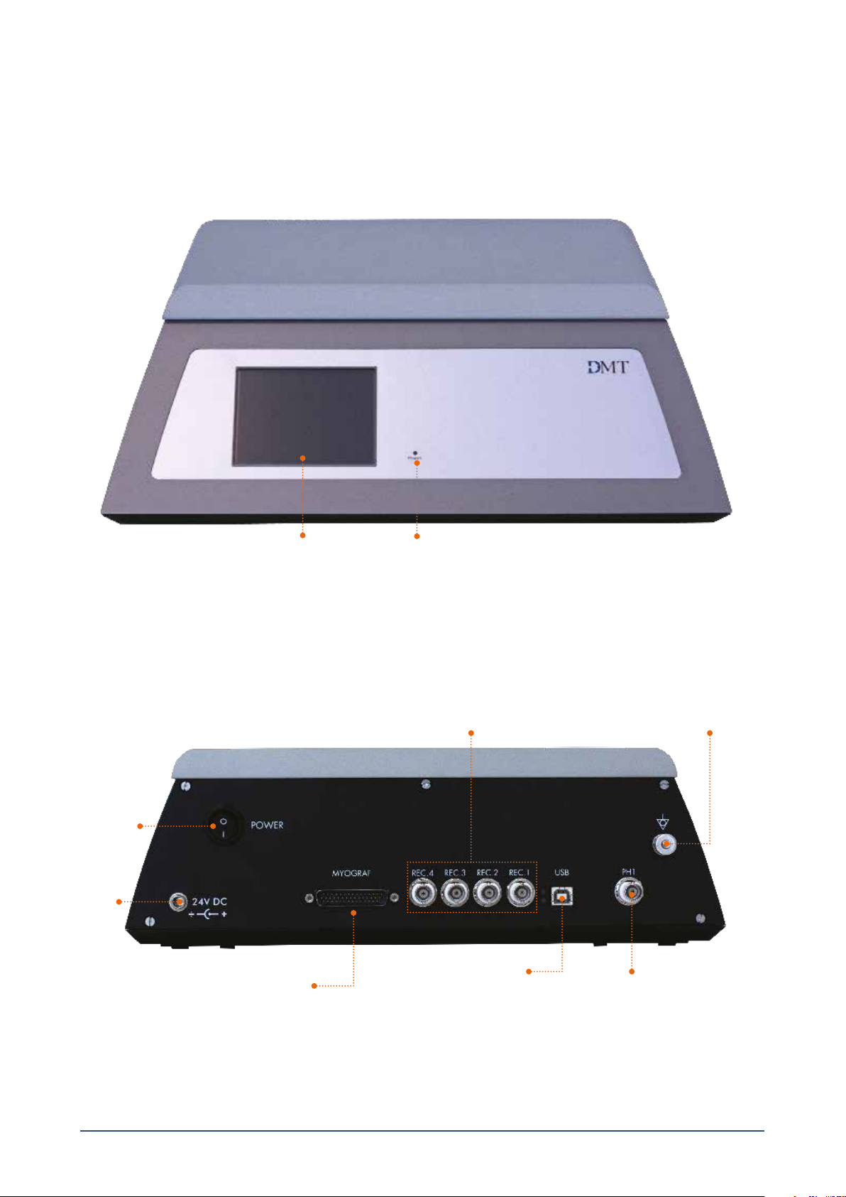
1.1 Wire Interface - front and rear.............................................................................................................................................................................................6
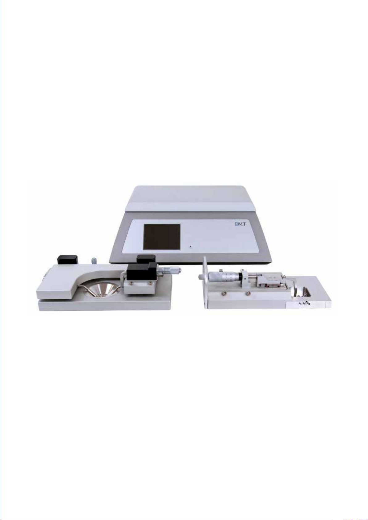
1.2 Wire Myographs.......................................................................................................................................................................................................................7
1.2.1 Confocal Wire Myograph - 360CW.............................................................................................................................................................................7
1.2.2 Single Wire Myograph - 320A......................................................................................................................................................................................8
Chapter 2 - Setting up ..................................................................................................................................................................................................................9
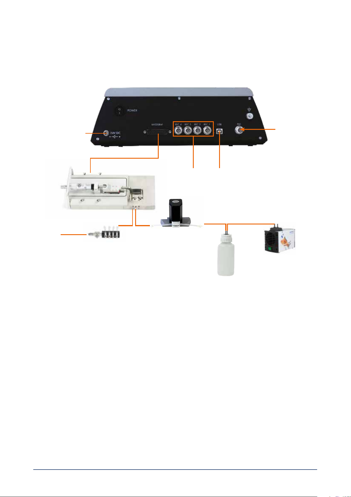
2.1 Setting up the complete Wire Myograph System .......................................................................................................................................................9
2.2 The rst force calibration................................................................................................................................................................................................... 10
Chapter 3 - The wire Interface Menus.................................................................................................................................................................................. 11
3.1 General description on how to navigate the touch screen................................................................................................................................... 11
3.2 Power-up screen................................................................................................................................................................................................................... 11
3.3 Main Menu.............................................................................................................................................................................................................................. 12
3.4 Zero Menu............................................................................................................................................................................................................................... 12
3.5 Heat Menu .............................................................................................................................................................................................................................. 13
3.6 Timer and Buzzer Menu ..................................................................................................................................................................................................... 13
3.7 Settings Menu ....................................................................................................................................................................................................................... 14
3.7.1 Force Calibration Menu............................................................................................................................................................................................... 14
3.7.2 pH Calibration Procedure........................................................................................................................................................................................... 18
3.7.3 Select Analog Output (optional) ............................................................................................................................................................................ 19
3.7.4 Interface Settings.......................................................................................................................................................................................................... 20
3.7.4.1 Temperature Dierence (oset)........................................................................................................................................................................ 20
3.7.4.2 pH Set-up Menu..................................................................................................................................................................................................... 20
3.7.4.3 Factory Diagnostics............................................................................................................................................................................................... 20
Appendix 1 - System specications...................................................................................................................................................................................... 21
Notes................................................................................................................................................................................................................................................ 23

5WIRE MYOGRAPH SYSTEM - 360CW/320A - USER MANUAL
SAFETY
The Wire Myograph System has been designed for use only in teaching and research applications. It is not intended for clinical
or critical life-care use and should never be used for these purposes. Nor for the prevention, diagnosis, curing, treatment, or
alleviation of disease, injury, or handicap.
• Do not open the apparatus: the internal electronics pose a risk of electric shock.
• Do not use this apparatus near water.
• To reduce the risk of re or electric shock, do not expose this apparatus to rain or moisture. Objects lled with liquids should
not be placed on the apparatus.
• Do not block any ventilation openings. Install in accordance with the manufacturer’s instructions.
• Do not install near any heat sources such as radiators, heat registers, stoves, or other apparatus that produce heat.
• Only use attachments and accessories specied by the manufacturer.
• Unplug this apparatus during lightning storms or when unused for long periods of time.
The Wire Interface is delivered with an external 100-240VAC to 24VDC adapter. Protect the power adapter and cord from being
walked on or pinched. Particularly at power plugs and the point where they connect to the apparatus. Refer all servicing to
qualied service personnel. Servicing is required when the apparatus has been damaged in any way; such as, the power-supply
cord or plug is damaged, liquid has spilled onto or objects have fallen into the apparatus, the apparatus has been exposed to rain
or moisture, does not operate normally, or has been dropped.
EC DECLARATION OF CONFORMITY
Danish Myo Technology A/S
Certify and declare that the following apparatus:
Wire Myograph System - DMT360CW, DMT320A
Restrictive use: Only for laboratory use.
Manufactured by:
Danish Myo Technology A/S
Skejbyparken 152
8200 Aarhus N.
Denmark
Conforms with the essential requirements of the EMC Directive 2004/108/EC.
Based on the following specications applied by:
EN 61326-1:2006
EN 61326-2-6:2006
EN 61326-2-6/Corr.:2007
And with the LVD Directive 2006/95/EC.
Based on the following specications applied by:
EN 61010-1:2010
EN 61010-2-030:2010
General warnings regarding EMC:
Do not use this device in close proximity to sources of strong electromagnetic radiation (e.g. unshielded intentional RF sources),
as these may interfere with the proper operation.

6UNPACKING THE WIRE MYOGRAPH SYSTEM
UNPACKING THE WIRE MYOGRAPH SYSTEM
Please take a few minutes to carefully inspect your new Wire Myograph System for damage which may have occurred during
handling and shipping. If you suspect any kind of damage, please contact DMT immediately and the matter will be pursued as
quickly as possible. If the packing material appears damaged, please retain it until a possible claim has been settled.
We recommend that you store the packing material for any possible future transport of the Wire Myograph System. Please
contact DMT Sales Department for packing instructions if the original packing material is unavailable.
After unpacking your new Wire Myograph System, please use the following list to check that the system is complete:
Wire Interface
• Power supply (the shape of the AC plug varies by country; be sure that the plug has the right shape for your location)
Confocal Wire Myograph - 360CW or Wire Myograph - 320A
• Myograph connection cable with a temperature probe
• Plastic mounting jaws (360CW) or stainless steel mounting jaws with supports (320A)
• Chamber cover
Accessories:
• 1 x calibration kit (including bridge, T-balance and 2 gram weight)
• 1 x funnel
• 1 x stainless steel wire 40 µm
• 2 x Allen keys (360CW) or 3 x Allen keys (320A)
• 1 x high vacuum grease
• 1 x grease for protection of linear slides
• 4 x spare screws (360CW) for mounting of jaws or 5 x spare screws (320A)
• 1 x screwdriver
• 10 x spare cover glass od 12,0 x 0,17 mm
Optional Accessories:
• PowerLab
• LabChart
• DMT Device Enabler
• Stimulator
• pH meter
• Vacuum Pump
• Electronic vacuum valve
• Waste bottle
• Gas supply manifold

7WIRE MYOGRAPH SYSTEM - 360CW/320A - USER MANUAL
CHAPTER 1 SYSTEM OVERVIEW
1.1 Wire Interface - front and rear
Figure 1.2 Wire Interface - rear
ON/OFF switch
24V DC port
for power
Connection port for
Wire Myograph
Analogue recorder output - connection to
external data acquisition software (optional)
USB connection port
for computer Connection port
for pH meter
(optional)
Grounding, connect to
Data Acquisition
Figure 1.1 Wire Interface - front
Power indicator
Touch display

8CHAPTER 1
Window in the base of the
chamber for imaging
Figure 1.3 Confocal Wire Myograph - 360CW with close-up of the chamber
25-pin serial cable for communication
with Wire Interface
Allen screws for ne alignment
of the wire jaws
Wire jaw connected to
force transducer
Force transducer pin
Vertical micrometer screw
Wire jaw connected to
horizontal micrometer
Horizontal micrometer
1.2 Wire Myographs
1.2.1 Confocal Wire Myograph - 360CW

9WIRE MYOGRAPH SYSTEM - 360CW/320A - USER MANUAL
1.2.2 Single Wire Myograph - 320A
Port for connection to Wire Interface
Wire jaw connected to force transducer
Wire jaw connected to
micrometer
Micrometer
Suction pipe for connection
to vacuum pump
Pipe for gas supply Pipe for lling the chamber
(using the 40 mm funnel)
Window at the bottom of the
chamber for imaging
(under the wire jaws)
Force transducer pin
Figure 1.1 Single Wire Myograph with close-up of chamber
Transducer house
Allen screws for ne alignment of the
wire jaws (2 on each side)

10
CHAPTER 2 SETTING UP
2.1 Setting up the complete Wire Myograph System
Figure 2.1 Example of a complete Wire Myograph System - 320A
CHAPTER 2
Figure 2.1 is an example of a complete set-up for the Wire Myograph System - 320A. A set-up for Confocal Wire Myograph would
look the same but with a Confocal Wire Myograph instead. The set-up includes optional equipment such as pH meter for measur-
ing pH in the buer, an electronic vacuum valve, suction bottle, vacuum pump, a computer and Data Acquisition System.
IMPORTANT
TO RECORD A NOISEFREE SIGNAL IT IS IMPORTANT TO CONNECT THE WIRE INTERFACE GROUND CONNECTION TO THE
DATA ACQUISITION SYSTEM’S GROUND CONNECTION.
1. Wire Myograph to Wire Interface connection:
Connect the Wire Myograph to the Wire Interface using the grey 44/25-pin connector cable. The end of the cable with the
temperature probe is attached to the Wire Myograph.
2. Wire Interface to computer connection:
Data acquisition is possible either by connecting the Wire Interface directly to a computer, or through a Data Acquisition
System able to collect voltage output (0-2.5volts) such as a PowerLab Data Acquisition System or similar system.
• Direct computer USB connection for Labchart (AD Instruments) users (latest version of Labchart):
Connect the Wire Interface to the computer with the USB cable from the back panel to the USB port.
• Analog Data Output through a PowerLab or similar Data Acquistion System (optional):
Connect the Wire Interface to the analog data acquisition system using BNC cables. Connect Rec 1 (Chamber 1) on the
Wire Interface to Input 1 on the analog data acquisition system. Rec 2 (Chamber 2) to Input 2 on the analog data acqui-
sition system 2, and so forth. Connect the analog data acquisition system to one of the USB-ports on the computer.
Gas supply manifold
Data Acquisition System
via BNC cables or USB
Wire Interface
rear panel
Wire Myograph
pH Meter
Oxygen/
Carbogen/
Compressed air
Vacuum Pump
Suction Bottle
Electronic vacuum valve
Power supply

11 WIRE MYOGRAPH SYSTEM - 360CW/320A - USER MANUAL
Suction pipe for connection
to vacuum pump
Pipes for gas supply
Figure 2.3 Chamber cover for for Confocal Wire Myograph 360CW
2.2 The rst force calibration
Prior to shipping, the Wire Myograph System has gone through two days of continuous testing including nal force calibrations.
However, DMT recommends that a new force calibration is performed before using the Wire Myograph System. The force calibra-
tion procedure is described in detail in chapter 3.7.1.
Figure 2.4 Pipes on the side of Wire Myograph 320A
Suction pipe for connection
to vacuum pump
Pipe for gas supply
3. Turn on the Power:
Turn on the power to the Wire Interface at the power switch and then turn on the computer. Start the data acquisition pro-
gram on the computer and the Wire Myograph System is now ready for use.
4. Gas supply:
Connect the pipes for gas supply on the Confocal Wire Myograph 360CW chamber cover (see gure 2.3) to an adjustable
gas supply using thin silicone tubing. For the Wire Myograph 320A connect the pipe for gas supply on the Wire Myograph
side, see gure 2.4.
5. Suction connection:
Connect the suction pipe on the Confocal Wire Myograph 360CW chamber cover (see gure 2.3) to a vacuum pump via a
suction bottle and the electronic vacuum valve (optional). For the Wire Myograph 320A connect the suction pipe on the Wire
Myograph side, see gure 2.4.
6. pH electrode (optional):
Connect the pH electrode to the pH port on the rear of the Wire Interface.
Pipe for lling the chamber

12
CHAPTER 3 THE WIRE INTERFACE MENUS
This chapter contains a detailed description of how to navigate the touch screen menus and how to use the special features of
the Wire Interface.
3.1 General description on how to navigate the touch screen
Menus on the Wire Interface are all accessible by a touch screen. To access
a menu, simply touch the screen. When a setting needs to be changed,
press SELECT beside the line to be changed.
The line to be modied will turn blue, indicating that the Wire Interface is
waiting for input. When ALL is chosen, all lines corresponding to all four
channels will turn blue.
Changing the numeric value for the chosen parameter can be done by
pressing UP or DOWN arrows.
Once the desired setting has been chosen, pressing ENTER will lock the
selection and be stored in memory.
Pressing the white X in the red box will exit the menu and take you automati-
cally to the Main Menu.
3.2 Power-up screen
After turning on the Wire Interface, an introduction screen appears. It dis-
plays the product system, model no., software version number, date and the
system ID number.
The system is auto-initializing while this screen is displayed.
The login screen appears after a few seconds if it is a new unregistered Wire
Interface. If already registered the Main Menu display will appear.
Before the Wire Interface can be used you need a login code. Go to the DMT
website www.dmt.dk and follow the registration procedure to obtain the
login code.
Enter the login code and press ENTER.
CHAPTER 3

13 WIRE MYOGRAPH SYSTEM - 360CW/320A - USER MANUAL
Buzzer icon:
This icon indicates the status on the Buzzer.
If the icon is grey the Buzzer is OFF.
If the icon is green the Buzzer is ON (active) and will make a sound when
the timer reaches zero.
Timer:
The Timer is a countdown timer that can be set to maximum 24 hours. If the
Buzzer is activated it will buzz when the timer reach zero.
Heat icon:
This icon indicates the status of the chamber heat.
If the icon is grey the Heat is OFF.
If the icon is green the Heat is ON (active).
Four sub-menus are accessible from the Main Menu screen:
Zero Menu
Heat Menu
Timer/Alarm Menu
Setting Menu
Icon for Heater ON/OFF *
Timer
Icon for Buzzer ON/OFF *
* If ON the icon is green
Zero Menu
Heat Menu
Timer/Alarm Menu
Settings Menu
OFF ON
00:00:00
OFF ON
3.3 Main Menu
The Main Menu gives a good overall status on how the Wire Interface is working. It displays the force, pH, probe temperature,
timer and the active status (buzzer, timer, heat).
3.4 Zero Menu
Is used to zero the output from the force transducer. Pressing ZERO will reset the baseline of the chart traces without aecting
the calibrations.

14
CHAPTER 3
3.5 Heat Menu
The heating temperatures are controlled from this menu. To turn the heat
on, or to change the temperature for the system, press HEAT in the Main
Menu. The Heat Menu will be displayed allowing the user to change the
system temperature, as well as turn the heat on or o. Pressing DEFAULT
will automatically reset the temperature setpoint to 37°C. Manually change
the temperature by pressing UP or DOWN arrows. Pressing ENTER will save
the new temperature setpoint.
To turn the heat on press ON and it will turn green. The system will heat to
the desired temperature setpoint. In the Main Menu the heat icon turns
green when the heat is on.
3.6 Timer and Buzzer Menu
The timer and buzzer are controlled from this menu. Use SELECT to program
the timer. The timer can be programmed in the interval from 0 to 23:59:59
(Hours : minutes : seconds). When Set Timer is selected use the UP and
DOWN arrows to program the timer. Use the RIGHT arrow to move from
hours, minutes and seconds. Press ENTER to save the programmed time.
To start the timer press ON and it will turn green.
When the timer reaches zero it automatically switches to OFF.
If the buzzer is turned on it will make a tone when the timer reaches zero.
ON

15 WIRE MYOGRAPH SYSTEM - 360CW/320A - USER MANUAL
To activate the buzzer press ON and it will turn green.
In Main Menu the bell icon also turns green.
3.7 Settings Menu
The Setting Menu contains several sub-menus. These sub-menus include:
Force calibration
pH calibration
Record out select
Interface settings
ON
3.7.1 Force Calibration Menu
Prior to shipping the Wire Myograph System has gone through two days of continuous testing, including nal force calibrations.
However, DMT recommends that new force calibrations are performed before starting to use the Wire Myograph System for the
rst time.
Begin the calibration procedure by pressing Force Calibration in the Settings Menu. The calibration procedure is listed in 6 indi-
vidual steps and needs to be performed to calibrate the system. Before starting the Force calibration the following is performed.
• Place the calibration bridge and T-balance on the Wire Myograph (see gure 3.1 for 360CW or 3.2 for 320A) allowing it to
be warmed up together with the Wire Myograph. Turn on the heating in the Heat sub-menu to the appropriate temperature
used during your experiments
• Mount a 40 m stainless steel wire on the jaws connected to the force transducers.
NOTE
THE WEIGHT SHOULD NOT BE PLACED ON THE TBALANCE YET.
Step 1 - Involves setting up the chamber for calibration. Fill the chamber to
a normal level with double distilled water. Move the jaws apart.
Press NEXT STEP.
IMPORTANT
TURN ON THE HEAT AND SET THE TEMPERATURE AT THE LEVEL AT WHICH
THE EXPERIMENTS WILL BE PERFORMED.

16CHAPTER 3
Figure 3.2 Force calibration set-up - showing placement of the calibration bridge and T-balance
for Wire Myograph - 320A
Figure 3.1 Force calibration set-up - showing placement of the calibration bridge and T-balance
(with weight in place) for Wire Myograph - 360CW
The 2 g weight is placed on the pan

17 WIRE MYOGRAPH SYSTEM - 360CW/320A - USER MANUAL
Figure 3.3 Illustration of how to t the T-balance pin between the wire and the gap in the jaw support
Step 2 - Involves setting up the Calibration Kit for the actual force calibra-
tion. Make sure that the T-balance pin is placed between the wire and the
jaw as illustrated in gure 3.3. Carefully move the calibration bridge until the
tip of the T-balance pin is placed freely between the wire and the jaw, which
means it does not touch the wire or the jaw, see gure 3.3.
Press NEXT STEP when the calibration kit has been properly placed.
Step 3 - Initiates the heating process for the chambers if not already done.
In order for the calibration to be accurate, the transducers must be heated
to the experimental temperature to be used. This accommodates heat-in-
duced expansion of the electronic parts in the transducer. Otherwise, inac-
curate readings and transducer drift may occur, producing errors into the
experiment.
Covering the chamber with the chamber cover will expedite the heating.
Place the temperature probe into the chamber for the rst calibration to
determine when the chamber has reached the target temperature. Heating
will take about 20 to 30 minutes for the chamber and transducer to reach
37°C with the chamber cover in place. Once the chamber are heated and
have reached the target temperature, press NEXT STEP.

18CHAPTER 3
Step 4 - is the rst step in the actual force calibration process. A four digit
number will be displayed in blue at the bottom of the screen. If nothing has
been disturbed during the heating process, the zero, 0 gram, or 0.0 mN
calibration should be stable as indicated by the four digit number. Wait at
least 30 to 45 seconds until the four digit number is stable before pressing
NEXT STEP.
NOTE:
NORMAL OPERATING VALUES FOR THE FORCE TRANSDUCER DURING
CALIBRATION SHOULD BE BETWEEN 3000 AND 3500. IF THE VALUE
IS 0, A SINGLE DIGIT, OR A THREE DIGIT NUMBER, THE FORCE TRANS
DUCER IS BROKEN AND NEEDS TO BE REPLACED. IF THE VALUE IS LESS
THAN 2000 OR GREATER THAN 4500 BUT STILL A FOUR DIGIT NUM
BER, THE FORCE TRANSDUCER IS BROKEN BUT SHOULD BE ABLE TO BE
REPAIRED BY A TEMPERATURE COMPENSATION DONE BY DMT. IF THE
MESSAGE OFF IS DISPLAYED ON THE MAIN PAGE OF THE INTER FACE,
EVEN THOUGH THE CHAMBER IS PLUGGED IN AT THE REAR OF THE
WIRE INTERFACE, THE FORCE TRANSDUCER IS BROKEN AND NEEDS TO
BE REPLACED. IN ADDITION, IF THE FORCE READINGS APPEAR YEL
LOW, CANNOT BE RESET TO ZERO, AND THE TRANSDUCER CANNOT BE
RECALIBRATED, THE FORCE TRANSDUCER IS BROKEN AND NEEDS TO
BE REPLACED.
Step 5 - At this step, place the 2 gram weight at the pan on the calibration
T-balance closest to the transducer (over the transducer) see gure 3.1 or
3.2, to simulate the stretch created by the contraction of a mounted ring
preparation.
Remember, a 2 gram weight in a 90° vector is divided, and the transducer
will only detect 1 gram or 9.81 mN of force. The weight placement should
cause a positive increase in the four digit number. Wait at least 30 to 45
seconds for the applied force to stabilize before pressing NEXT STEP.
Step 6 - is to verify that the calibration was performed correctly. The Force
Chamber reading should be 9.81 ± 0.1 mN. If the Force Chamber reading is
o by more than 0.1 mN, then remove the weight, press BACK to return to
Step 4, and repeat the calibration process. If the Force Chamber reading is
satisfactory, then press NEXT STEP to end the calibration.
After calibrating the force transducer, carefully remove weight, T-balance
and calibration bridge. The Wire Myograph System is now ready for force
measurements.

19 WIRE MYOGRAPH SYSTEM - 360CW/320A - USER MANUAL
3.7.2 pH Calibration Procedure
Before the pH calibration is performed, be sure to select the way the pH electrode is intended to be used. See pH Set-up Menu
(under Interface Settings) in chapter 3.7.4.2.
The temperature is an important parameter in the calibration formula and is obtained automatically if the Temperature com-
pensation has AUTO selected. If MANUAL is chosen, the Manual temperature is used in the pH calibration formula, and the
temperature probe is not used. In the MANUAL mode, the temperature of the calibration buers is measured with a thermometer
and entered manually in the Manual temperature line.
The calibration procedure is listed in 4 individual steps and needs to be performed one by one to calibrate the pH
Step 1 - Involves cleaning the pH electrode and the temperature probe with
double-distilled water. When ready press NEXT STEP.
Step 2 - Place the pH electrode and temperature probe in the high buer
solution (here pH 7) and turn on stirring. When the relative pH output in the
blue line is stable, press NEXT STEP.
Step 3 - Place the pH electrode and temperature probe in the low buer
solution (here pH 4) and turn on stirring. When the relative pH output in the
blue line is stable, press NEXT STEP.

20CHAPTER 3
Step 4 - The calibration is now nished. The readings in the two bottom lines
are the actual pH and temperature readings.
3.7.3 Select Analog Output (optional)
The Analog Output Menu determines what will be sent to the BNC analogue
output (REC 1, REC 2 REC 3, REC 4 at the back of the Wire Interface). There
are 4 analog outputs, and each output is individually programmable. Any
change made to the analog output will aect the data sent from the Wire
Interface to a data acquisition system such as AD Instruments PowerLab.
Therefore remember to check the data acquisition system’s set-up when a
change is made. The analog output is working in range of -2,5V to +2,5V.
Use SELECT to select the out channel number to be changed. Press ENTER
to go to the output set-up.
Use SELECT to select the line to be changed. Use the UP and DOWN arrow
or DEFAULT to change/select a new set-up.
The following parameters in the Wire Interface can be selected as output to
the analog channels. Force Near, Force Far, Temperature Probe, Chamber
Temperature, pH1, (Optional: Digital Output 1, Digital Output 2, Digital Input
1, Digital Input 2).
When the chosen parameter is selected press ENTER to save the value in
the memory.
The output range is -2,5V to +2,5V. The user can select the parameter value
that gives -2,5V and the value that gives +2,5V. In this example -100mN is
-2,5V and +100mN is +2,5V. Selecting asymmetrical values is also valid.
They can be -2,5V = 0mN and +2,5V = 100mN.
NOTE
REMEMBER TO PRESS ENTER TO SAVE THE LINE CHANGES IN MEMORY.
This manual suits for next models
1
Table of contents
Other DMT Laboratory Equipment manuals