6LG 5929 / 121113 / 284
Caractéristiques techniques Caractéristiques techniques
Entrée
Tension assignée UN:24 V AC/DC, 110 / 115V AC/DC,
110 / 115 V AC, 230 / 240 V AC *)
*) voir marquage appareil
Plage de tensions 0,85 ... 1,1 UN AC
à 10% d'ondulation résiduelle: 0,9 ... 1,1 UN DC
à 48% d'ondulation résiduelle: 0,85 ... 1,1 UN DC
Consommation nominale à UN
24 V AC/DC: 1,8 VA
110 / 115 V AC/DC: 2,0 VA
110 / 115 V, 230 / 240 V AC: 3,0 VA
Fréquence assignée: 50 / 60 Hz
Courant de commande
à 24 V sur 2 modules: 75 mA
Sortie
Garnissage en contacts
LG 5929.60, LG 5929.60/100: 5 contacts NO,
1 NF pour le circuit de retour
LG 5929.54, LG 5929.54/100: 4 contacts NO, 1 NF,
1 NF pour le circuit de retour
Temps de réponse: max. 20 ms
Temps de retombée: max. 35 ms
Type de contacts: relais à sécurité positive
Tension assignée de sortie: 250 V AC
Courant thermique Ith:voir courbe de courant totalisateur*)
max. 5 A
*) voir fiche LG 5929 sur www.dold.com
Pouvoir de coupure
en AC 15
contact NO: 3 A / 230 V AC IEC/EN 60 947-5-1
contact NF: 2 A / 230 V AC IEC/EN 60 947-5-1
en DC 13
contact NO: 2 A / DC 24 V IEC/EN 60 947-5-1
contact NF: 2 A / DC 24 V IEC/EN 60 947-5-1
en DC 13
contact NO: 4 A / 24 V à 0,1 Hz IEC/EN 60 947-5-1
contact NF: 4 A / 24 V à 0,1 Hz IEC/EN 60 947-5-1
Longévité électrique
en AC 15 pour 2 A, 230 V AC: 105manoeuvres IEC/EN 60 947-5-1
Cadences admissibles : 1200 manoeuvres / h
Tenue aux courts-circuits,
calibre max. de fusible: 10 A gL IEC/EN 60 947-5-1
petit disjoncteur: B 6 A
Caractéristiques générales
Type nominal de service: service permanent
Plage de températures
opération: - 15 ... + 55 °C
stockage: - 25 ... + 85 °C
altitude: < 2.000 m
Distances dans l'air
et lignes de fuite
Catégorie de surtension /
degré de contamination: 4 kV / 2 (isolation de base)IEC 60 664-1
CEM
Décharge électrostatique: 8 kV (dans l'air) IEC/EN 61 000-4-2
Rayonnement HF: 10 V / m IEC/EN 61 000-4-3
HF induite par conducteurs: 10 V IEC/EN 61 000-4-6
Tensions transitoires : 4 kV IEC/EN 61 000-4-4
Surtensions
entre câbles d'alimentation: 1 kV IEC/EN 61 000-4-5
0,5 kV IEC/EN 61 000-4-5
en 24 V AC / DC
entre câbles et terre: 4 kV IEC/EN 61 000-4-5
HF induite par conducteurs: 10 V IEC/EN 61 000-4-6
Antiparasitage: seuil classe B EN 55 011
Degré de protection:
boîtier: IP 40 IEC/EN 60 529
bornes: IP 20 IEC/EN 60 529
Boîtier: thermoplastique à extinguibilité V0
selon UL Subj. 94
Résistance aux vibrations: amplitude 0,35 mm
fréquence: 10 ... 55 Hz, IEC/EN 60 068-2-6
Résistance climatique: 15 / 055 / 04 IEC/EN 60 068-1
Repérage des bornes: EN 50 005
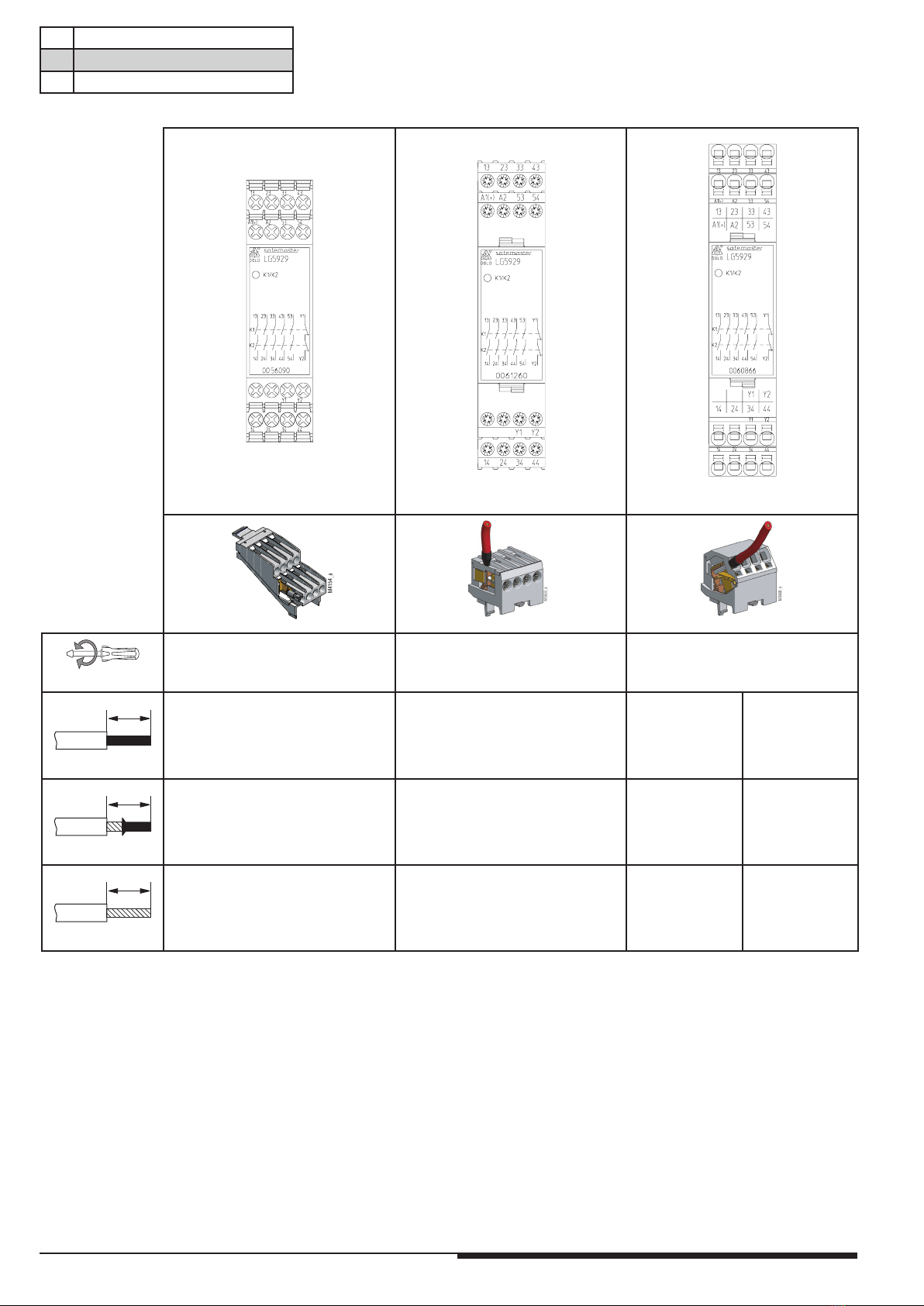
Fixation des conducteurs: vis de serrage cruciformes imperdables
M 3,5 bornes intégrées avec protection
contre la rupture de conducteur ou
bornes ressorts
Fixation instantanée: sur rail IEC/EN 60 715
Poids net: 205 g
Diagnostics des défauts
Défaut Cause possible
DEL "K1/K2" ne s'allume pas L'alimentation n'est pas connectée
Entretien et remise en état
- Cet appareil ne contient pas de composants requérant un entretien.
- En cas de disfonctionnement, ne pas ouvrir l'appareil, mais le renvoyer
au fabricant.
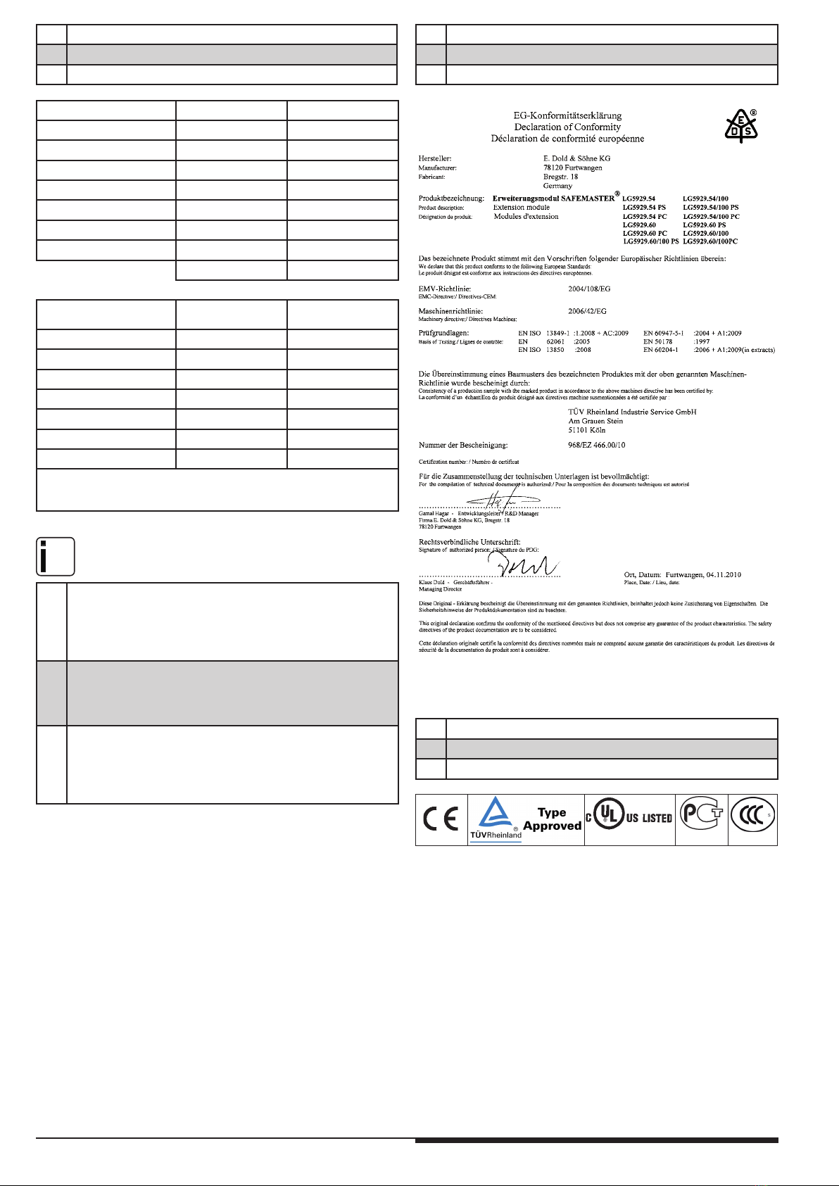
Données UL
Les fonctions sécuritaires de l‘appareil n‘ont pas été analysées
par UL. Le sujet de l‘homologation est la conformité aux standards
UL 508, „ general use applications“
Pouvoir de coupure:
Température ambiante 45°C: Pilot duty B300
5A 250Vac G.P.
5A 24Vdc
Température ambiante 55°C: Pilot duty B300
4A 250Vac G.P.
4A 24Vdc
Connectique: uniquement pour 60°/75°C
Fixes avec bornes à vis: AWG 20 - 12 Sol/Str Torque 0.8 Nm
Débrochables avec bornes à vis: AWG 20 - 14 Sol Torque 0.8 Nm
AWG 20 - 16 Str Torque 0.8 Nm
Débrochables avec bornes ressorts: AWG 20 - 12 Sol/Str
nfo
Les valeurs techniques qui ne sont pas spécifiées ci-dessus
sont spécifiées dans les valeurs techniques générales.
Variantes
LG 5929._ _ /100: pour couplages à 2 canaux,
avec 2 DEL