Doran 4100XL User manual

Digital Checkweigher Scale
INSTRUCTION MANUAL
DORAN SCALES, INC.
1315 PARAMOUNT PKWY.
1-800-262-6844
FAX: (630) 879-0073
http://www.doranscales.com
MANUAL REVISION: 0.3
MAN0197 12/3/2001
Model 4100XL
Made in USA

1
Table of Contents
Table of Contents.......................................................................................1
Introduction................................................................................................3
Quick Start User's Guide...........................................................................4
Fig. 1: Model 4100XL Front Panel Layout.................................................................4
Power Up: ....................................................................................................................4
Basic Weighing Operation:...........................................................................................4
Controls and Display Operation: ..................................................................................5
Zero:.............................................................................................................................5
Units: (Optional) ...........................................................................................................5
Print: (Optional)............................................................................................................5
Installation:...................................................................................................................5
Electrical Connections:.................................................................................................5
Quick Setup Guide.....................................................................................6
Load Cell and Power Connections:..............................................................................6
Fig. 2: Load Cell / Power connections.......................................................................6
Option Connections:.....................................................................................................6
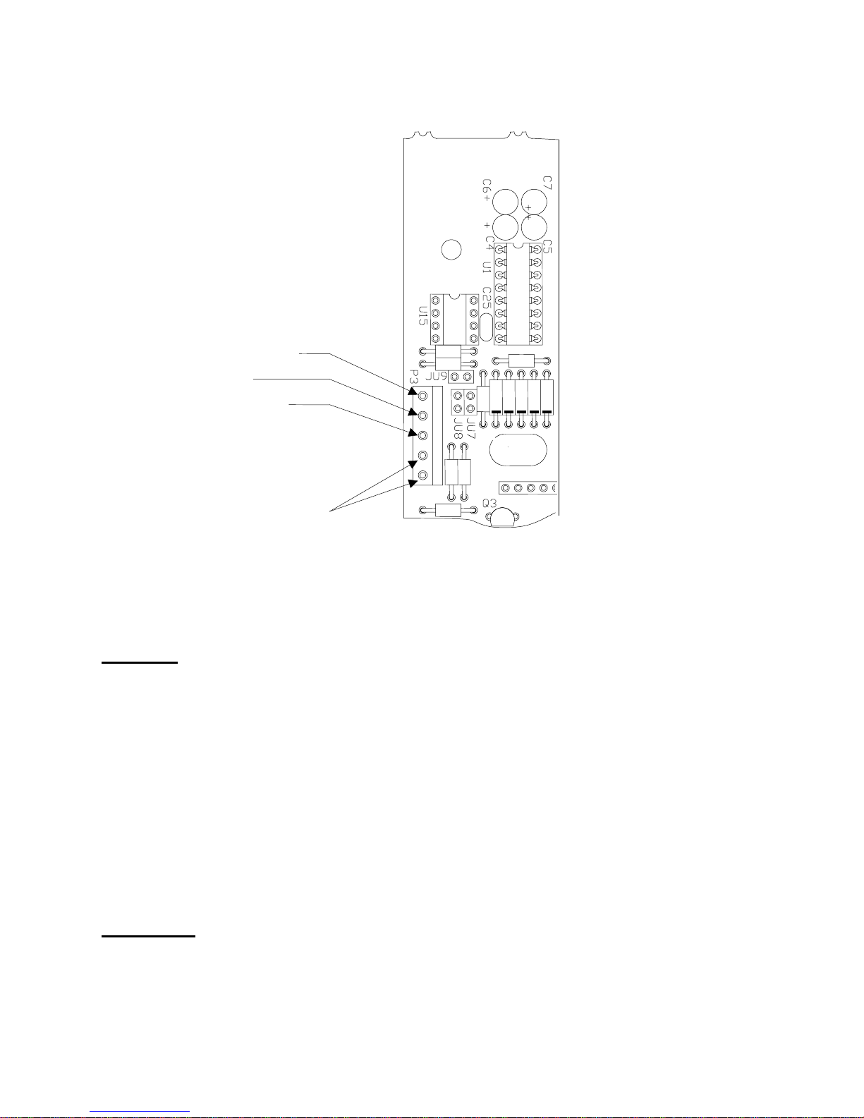
Fig. 3: Remote Push Button Connections .................................................................7
Detailed Parameter Setup........................................................................10
Entering and Exiting the Calibration Setup Menu:.....................................................10
Fig. 4: Quick Access Panel .....................................................................................10
Stepping through the menu parameters:....................................................................10
Changing a Parameter:..............................................................................................11
Quick Review of Setup Parameters:...........................................................................11
Legal for Trade Restrictions:......................................................................................11
Setup Menus Explained...........................................................................12
Capacity Setup Menu..............................................................................................13
Calibration Menu.....................................................................................................13
Over and Under Setup Menu ..................................................................................14
Digital Filter Setup Menu.........................................................................................14
Automatic Zero Tracking Setup Menu.....................................................................15
Motion Aperture Setup Menu ..................................................................................15
Start Up Zero Setup Menu ......................................................................................15
Latching Zero Request Setup Menu........................................................................15
Latching Print Request Setup Menu........................................................................16
Printer Data Output Setup Menu.............................................................................16
Output Formats .......................................................................................................16
Baud Rate Setup Menu...........................................................................................16
Serial Data Handshaking Setup Menu ....................................................................17
Units Conversion Setup Menu.................................................................................17
Start Up Units Selection Menu ................................................................................17
Remote Push-button Configuration Menu...............................................................18
Legal For Trade Setup Menu ..................................................................................18
Scale Resolution Setup Menu.................................................................................18
Raw Counts Display Mode......................................................................................18

2
Data Communications.............................................................................19
Introduction to data communications:.........................................................................19
Printer Modes:............................................................................................................20
Transmit on demand (tod):......................................................................................20
Continuous print (CP):.............................................................................................20
Auto Print 1 (AP1): ..................................................................................................20
Auto Print 2 (AP2): ..................................................................................................20
Data output format:.....................................................................................................21
"F0" Format:............................................................................................................21
Fig. 1 Format "F0" standard form............................................................................21
Fig. 2 Format "F0" lb-oz form ..................................................................................22
Fig. 3 Format "d0" form...........................................................................................22
"d0" Format: ............................................................................................................22
Fig 4. Sample SS0 Format printer output................................................................23
"SS0" format:...........................................................................................................23
Specifications and Interconnect Data....................................................24
Specifications:............................................................................................................24
Table 9: Scale Specifications ..................................................................................24
Interconnect Data:......................................................................................................24
Table 10: TB1 Load Cell Connections.....................................................................24
Table 11: P3 Options Connections..........................................................................25
Table 12: J4 Power Connections.............................................................................25
Table 13: P4 Keyboard Connections.......................................................................25
Fig. 5: Connector J3, Remote switch cable assembly.............................................25
Fig. 6: Connector J3, Serial cable assembly ...........................................................26
Table 14: Serial Cable assembly with Hardware Handshaking...............................26
Table 15: Serial Cable assembly with Software Handshaking ................................27
Fig. 7: Installation of EMI / RFI / ESD protection devices........................................28
Troubleshooting.......................................................................................29
General problem resolution:.......................................................................................29
Resetting the scale parameters:.................................................................................30
Resetting the scale:....................................................................................................30
Scale Messages:........................................................................................................31
Error messages:.........................................................................................................31

3
Introduction
Introducing the Doran Scales, Inc. Model 4100XL Digital Checkweigher Scale. This
scale uses state of the art technology to provide you with a low cost solution to the most
demanding weighing applications. With ease of use and setup in mind, the scale is
simple to set up and ready to use. The Model 4100XL offers many features. A few of
these features are listed below:
NTEP certification for Class III installations to 5,000d.
A six digit, 0.56" red LED display for easy reading.
lb, kg, oz, g, lb-oz display units supported.
Fully configurable duplex printer port with RS232 support.
EEPROM nonvolatile data storage of all calibration and setup information.
Microprocessor monitoring system to prevent scale failure under severe
fault conditions.
115/230 VAC 50/60 Hz (jumper selectable) operation.
Field selectable digital filtering.
Software configurable remote push-button support (Optional).
Please be sure to read the entire manual to ensure obtaining all the benefits that the
Model 4100XL can provide. If any questions arise, please feel free to contact the Doran
Scales Technical Support Department at 1-800-262-6844.
Unpacking Your Scale
Before unpacking your Doran scale, please read the instructions in this section. Your
new scale is a durable industrial product, but it is also a sensitive weighing instrument.
Normal care should be taken when handling and using this product. Improper handling
or abuse can damage the scale and result in costly repairs that will not be covered by
the warranty. If you notice any shipping damage, notify the shipper immediately. Please
observe the following precautions to insure years of trouble free service from your new
scale.
DO NOT drop the scale.
DO NOT immerse the scale.
DO NOT drop objects on the platform.
DO NOT pick up the scale by the "spider."
Carefully remove the scale from the shipping carton.

4
Quick Start User's Guide
Fig. 1: Model 4100XL Front Panel Layout
Power Up:
Connect the Model 4100XL to a compatible power source.
Basic Weighing Operation:
1) Remove all items from the scale platter.
2) Press ZERO to zero the scale. The weight display should now read zero.
3) Place an item on scale platter and wait for the motion (MOT) indicator to go out,
indicating a stable weight.
4) Read the weight on the scale display.
Over, Under and Accept Checkweighing Operation :
1) Remove all items from the scale platter. (If checkweighing to zero, place the target
weight on the scale.)
2) Press ZERO to zero the scale. The weight indication should now be zero.
3) Place an item on scale platter and wait for the motion (MOT) indicator to turn off,
indicating a stable weight.
4) If the item is heavier than the over limit, the OVER light will light, If the item is lighter
than the under limit, the UNDER light will light. If the weight is between the limits, the
ACCEPT light will light.

5
Controls and Display Operation:
The operational controls for the Model 4100XL consist of the ZERO, and an optional
PRINT or UNITS button. A six digit LED display is used to provide weight indications
and operator messages describing scale operation. Scale status such as motion (MOT),
polarity (NEG), and center of zero (ZERO) is displayed on annunciators located to the
left of the display area. Scale units are indicated on four annunciators located to the
right of the main weight display.
Zero:
The ZERO button is used to zero the scale prior to making a reading. The ZERO button
can function over the full range of the scale or it can be limited to a zero band equal to
+1.9% of scale capacity for Canadian applications. To zero the scale, wait until the
scale is stable and press the ZERO button. The scale will zero immediately. The scale
will not "zero" if the scale is in motion.
Units: (Optional)
The UNITS button permits the operator to change the Model 4100XL display weight
units easily. Simply press the UNITS button and the scale will indicate the correct
weight in the new units, lb, kg, g, oz, lb-oz.
Print: (Optional)
The PRINT button permits the operator to print the current weight or send a data stream
to an external device. Like the ZERO button, the user must wait for motion to stop
before pressing the PRINT button. The current weight will then be transmitted to the
printer or external device.
Installation:
The desired scale location should be flat, level and free of any obstructions, which might
interfere with the operation of the scale platter. Remove the platter and locate the
bubble level inside the base. Adjust the four scale feet so the bubble is centered with
the base stable so it does not rock.
When installing your scale, make sure that the power connection is close to the scale
and easily accessible.
Electrical Connections:
Prior to connecting your Model 4100XL to power, check the serial number tag on the
scale for the correct operating voltage. Verify that the power matches the rated voltage.
Be sure the AC power is not excessively noisy - this can occur if large inductive loads,
such as solenoids or motors, are on the same power line. The Model 4100XL has a
filtered power supply to reduce the effects of normal line noise, but they cannot limit
severe fluctuations. If problems occur, noise-producing devices may have to be
suppressed to minimize their effect.

6
Quick Setup Guide
Load Cell and Power Connections:
Load cell connections are made through a terminal block located at the bottom center of
the main PC. Board (Fig. 2). See “Specifications and Interconnect Data” for wiring. The
power cord connects to a connector adjacent to the transformer. These connections
are accessible by removing the rear cover.
Fig. 2: Load Cell / Power connections
The Calibration (S1) and UNITS push buttons is located behind the Calibration Access
Cover. This cover is located near the top of the rear cover. There are no zero jumpers,
span jumpers, switches or pots to adjust. The calibration and UNITS push buttons can
be accessed by removing the Calibration access cover.
Option Connections:
The Remote Switch and Serial Communications connector is found on the left side of
the main PC. board. This connection is accessed by removing the rear cover.
Connections are made by either crimping (or soldering) a connector contact onto each
lead of the option cable. After crimping (or soldering), the contact is pressed into a
connector housing. The completed option connector is then snapped onto the option

7
connector found on the main board. Like the load cell cable and power cord, the option
cables are passed through watertight fittings mounted on the bottom of the indicator.
Fig. 3: Remote Push Button Connections
Capacity: Capacity selection is performed by pressing and release Calibration button
(S1) to enter the calibrate mode. Press and release UNITS until "CAP
50" appears on the display (where "50" can be any valid capacity). Once
the CAP prompt appears, press and release ZERO until the desired
capacity is displayed. When finished, press and release Calibration button
(S1) to exit Cal menu.
Once the desired capacity has been selected, place the correct capacity
label behind the capacity window located on the front panel. Secure the
label with tape.
Calibration: 1) Momentarily press Calibration button to enter CAL menu. Press and
release the UNITS button until "CAL 0" appears on the display.
TXD
REMOTE
SWITCH
DIGITAL GND.
CTS /RXD

8
2) Remove any unnecessary weight from the scale platter and wait for
about 10 seconds. Press ZERO and wait about 15 seconds. The display
will return.
NOTE: If "rg Err" appears on the display, the calibration zero is out of range. Press zero
to clear error. Refer to the analog setup section for additional information.
3) Press and release the UNITS button to scroll through the calibration
capacities. Select one of the following:
CAL FS: Full load calibration.
CAL .50: Half load calibration. (50% of full load)
CAL .25: Quarter load calibration. (25% of full load)
CAL .10: 1/10th load calibration. (10% of full load)
Place the correct weight on the platter and wait about 10 seconds. Press
ZERO. After about 15 seconds, the display will display "donE". Scale
exits out of CAL menu.
NOTE: If "SPAn E" appears on the display, the calibration span is out of range. Press
zero to clear error. Refer to the analog setup section for additional information.
NOTE: Calibration at 10% of capacity has been provided as a convenience to customers
with high capacity scales in remote or inaccessible locations. Scales calibrated
at 10% of capacity are more likely to have significant errors at full capacity than
are scales calibrated at 25% or 50%. Doran Scales recommends that all scales
be calibrated at full capacity whenever possible. 10% calibration should not be
used when calibrating scales for legal for trade applications.
NOTE: On scales with factory installed platforms, the zero and span will lie within
permissible limits. Use this section only if you are curious about the load cell
output.
Analog Setup:
1) Momentarily press the Calibration button to enter CAL menu. Press
and release the UNITS button until CAL 0 (where 50 can be any valid
capacity) appears on the display. Follow the procedure to select the
desired scale capacity.
2) Once the correct capacity has been selected, press and release UNITS
until in the raw counts mode.
3) Return the scale platform to "No Load" by removing any unneeded
items from the platform.

9
4) Record the "no load" counts.
5) Place "Full Load" on the platform and record the "Full Load" counts.
Subtract the "No Load" counts from the "Full Load" counts to calculate
span. Refer to Table 1 and verify that the span falls within the limits
specified for the amount of dead load present. If the readings, are outside
of the limits specified, change dead load or span until you meet the
requirements.
6) When using 50%, 25% or 10% of full load to calibrate, calculate the
span for the calibration weight in use. Divide the resulting span by .5, .25
or .1 respectively before comparing the span to the table. The "Full Load"
raw counts (span + dead load) should not exceed 70.0000 counts.
Dead Load Minimum Span
2.0000 to 17.5000 counts 5.3000 counts
17.5000 to 28.0000 counts 11.5000 counts
Table 1. Minimum span requirements

10
Detailed Parameter Setup
The Model 4100XL has 19 setup and calibration parameters, which can be accessed
through the scale's Calibration Setup Menu.
Entering and Exiting the Calibration Setup Menu:
To enter the Calibration Setup Menu. Remove the two screws mounting access cover.
Once opened, momentarily press the Calibration button (S1), location on main PC
board (see Fig. 4) to enter Calibration menu. The indicator will display the first menu
parameter, "CAL 50" (Where 50 can be any valid capacity).
Fig. 4: Quick Access Panel
To exit the Calibration Setup Menu, simply press and release the CAL button to exit
Calibration menu. The indicator will return to the normal weighing mode. All parameter
selections, will be saved, including any just changed.
NOTE: No setup information is saved until scale returns to the RUN mode. In the event
of a power failure while in the Calibration Setup Menu, any changes that have been
made will be lost.
After all setup changes are finished, and the indicator is in the normal weighing mode,
re-install the access cover. Make sure the access cover and all the screws are re-
installed in their original locations. Tighten the screws as needed.
Stepping through the menu parameters:
Once the Calibration Setup Menu has been entered, you may step through the menu by
pressing and releasing UNITS. A different display prompt will appear for each
parameter in the menu.
The parameter list on the following pages corresponds to the parameters available in
the Calibration Setup Menu.
Some of the menu parameters, when changed affect settings of other parameters. The
scale will limit these parameters or automatically set the parameters to meet the new
limits.
UNITS CAL

11
Changing a Parameter:
After finding the desired menu item, the parameters for that item may be changed.
Press and release ZERO to step through the parameter list for that item. The list of
choices will repeat if you keep pressing and releasing ZERO. When you have found the
desired setting, press UNITS to go to the next menu item.
Quick Review of Setup Parameters:
Setup parameters for the Model 4100XL may be quickly reviewed without opening the
scale. Remove power and press and hold the ZERO button while you apply power.
Hold the button until the scale begins to scroll through the setup parameters. The
button may be released anytime after the review has begun. After parameters are
displayed, scale will then go to the normal weighing mode automatically.
Legal for Trade Restrictions:
When the Legal for Trade mode is enabled, it automatically disables some menus and
parameter options. This is done to comply with NTEP requirements. The menus and
parameter sections are shown on the following pages. Those menus and/or parameters
not available when in the Legal for Trade mode are marked by an asterisk.

12
Setup Menus Explained
(In order of occurrence)
CAP CAL AVg AZt
5
Calibration Setup Menu
50
A0
A9
A7
A6
A5
A4
A3
2
4
8
16
32
oFF
0.5
1
3FS
0
m.A.
0.5
0.25
0.1
+4 SS0
SS1
SU0
on
oFF
Zod
on
oFF
Pod
on
oFF
HS
oFF
SF
Cts
CSL
C
A
L
g
o
Lh
UnitS
lb
k
g
Lo
g
o
oz
g
lb oz
r.P.b.
oFF
P
C
0
oP
Std
44
CAn
CtS
3
P
SP
XXXXX
d.o.
t.o.d.
C.P.
A.P.1
A.P.2
For.
F0
F1
d0
d1
1
3
5
br.
12
24
48
96
14.4
O.U.
10
25
100
+3
+2
oFF
+7
+5
+20
+1
+10
+15
+30
150

13
Capacity Setup Menu
CAP Capacity Select Menu
Allows the selection of scale capacity.
5 5 pounds
10 10 pounds
25 25 pounds 1
50 50 pounds
100 100 pounds
150 150 pounds
1) No lb-oz display for this capacity in super precision resolution.
Calibration Menu
CAL Zero Calibration Mode.
0 Calibration Zero
Press ZERO to perform calibration of the scale zero.
Successful calibration is indicated by "donE"
NOTE: The scale will automatically adjust the offset and gain to
compensate for dead load and span. When making these adjustments,
the scale may ask you to repeat zero calibration immediately after
performing a zero calibration or after a span calibration. Successful
calibration is indicated by "donE"
CAL Span Calibration Mode.
(Does not appear if CAL 0 is not activated.)
FS Full load calibration.
0.5 Half capacity calibration.
0.25 Quarter capacity calibration.
0.1 1/10th of capacity calibration.
* NOTE: For maximum accuracy, Doran Scales recommends that all
scales be calibrated at full capacity. When location or installation make
it difficult to bring full capacity weights to the scale, calibration with as
little 10% of capacity is possible.

14
Over and Under Setup Menu
O.U. Over and Under tolerances Select Menu Allows the
selection of Checkweighing band in scale
divisions.
oFF Checkweighing is off
1 +1 division
2 +2 division
3 +3 division
5 +5 division
7 +7 division
10 +10 division
15 +15 division
20 +20 division
30 +30 division
Digital Filter Setup Menu
Avg Averaging mode
Determines the number of samples to average
A0 Stabil-izer ©auto averaging. All readings are
averaged. Display updates 10 times a second.
A9 Stabil-izer ©auto averaging. All readings are
averaged. Display updates 9 times a second.
A7 Stabil-izer ©auto averaging. All readings are
averaged. Display updates 7 times a second.
A6 Stabil-izer ©auto averaging. All readings are
averaged. Display updates 6 times a second.
A5 Stabil-izer ©auto averaging. All readings are
averaged. Display updates 5 times a second.
A4 Stabil-izer ©auto averaging. All readings are
averaged. Display updates 4 times a second.
A3 Stabil-izer ©auto averaging. All readings are
averaged. Display updates 3 times a second.
2 Fixed averaging 2 readings are averaged. Display
updates 20 times a second.
4 Fixed averaging 4 readings are averaged. Display
updates 10 times a second.
8 Fixed averaging 8 readings are averaged. Display
updates 5 times a second.
16 Fixed averaging 16 readings are averaged. Display
updates 3 times a second.
32 Fixed averaging 32 readings are averaged. Display
updates 1½ times a second.

15
Automatic Zero Tracking Setup Menu
AZt Automatic Zero Tracking Range
Small weights within the specified number of
divisions are automatically zeroed.
oFF Zero tracking is off. No automatic zeroing.
0.5 Zero tracking to within 0.5 division.
1 * Zero tracking to within 1.0 division.
3 *Zero tracking to within 3.0 divisions.
Motion Aperture Setup Menu
m.A. * Motion aperture *
Determines how many divisions consecutive
readings must change before the scale is
considered in motion.
1 1 division change must be seen to enter motion.
3 3 division change must be seen to enter motion.
5 5 division change must be seen to enter motion.
Start Up Zero Setup Menu
SU0 * Start Up Zero
Controls the start up zero status.
on Zeros on the first stable reading on power up.
oFF Loads the calibration zero for zero reference
Latching Zero Request Setup Menu
Zod Zero on Demand
Enables or disable zero latching.
on If ZERO is pressed, it is saved until the scale
becomes stable.
oFF If the scale is in motion, the zero request is
discarded.
* NOTE: The Legal for Trade mode disables some options and selections
listed above. These items have been indicated by an asterisk.

16
Latching Print Request Setup Menu
Pod Print on Demand
Enables or disables print latching.
on If PRINT is pressed, the print request is saved until
the scale becomes stable.
oFF If the scale is in motion, the print request is
discarded.
Printer Data Output Setup Menu
d.o. Data Output Mode
Determines when serial data will be sent.
t.o.d. Transmit on demand. Print when the PRINT
button is pressed.
C.P. Continuous Print. Print when display is updated.
A.P.1 Auto Print 1. Print once only when scale goes stable.
A.P.2 Auto Print 2. Print once only when scale goes stable.
Scale must return to zero to before it can print again.
Output Formats
For. Data Input / Output Format
Defines the appearance of the serial data sent.
F0 Basic output format.
(See the Data Communication section for details)
F1 Enhanced Output includes Checkweigh status.
d0 Basic Dual Print Format. Includes Kilogram weight.
d1 Basic Dual Print Format. Includes Kilogram weight
and Checkweigh status.
SS0 Basic Output for Doran Model SSP printer.
SS1 Enhanced Output for Doran Model SSP printer.
Baud Rate Setup Menu
br. Baud Rate Setup
Determines baud rate for serial data.
12 1200 baud (bits per second)
24 2400 baud (bits per second)
48 4800 baud (bits per second)
96 9600 baud (bits per second)
14.4 14,400 baud (bits per second)

17
Serial Data Handshaking Setup Menu
HS Serial Data Output Handshaking
Selects the type of serial data handshaking used.
(See the Data Communication section for details)
oFF No handshaking is used. Data is sent when ready,
receiving device (printer) must be fast enough to keep
up with the data.
SF Software handshaking. Data is sent when ready.
Transmission can be controlled by the receiving
device. The software handshaking option
activates Bi-directional RS232 communications.
Refer to the communications section for details.
CtS CTS Handshaking. Data is sent only when CTS is
active.
Units Conversion Setup Menu
CSL Convert Select Modes
Determines which units selections will be active.
CA * Convert All. lb, kg, g, oz and lb-oz are active.
Lgo lb, kg, g and oz are active.
Lh lb and kg are active.
Lo lb and oz are active.
go g and oz are active.
Start Up Units Selection Menu
UnIts Start Up Units Select Mode
Configures selection of start up units.
Press ZERO to scroll through the units activated in
the CSL parameter. The selected units will be
displayed on the units indicators to the right of the
display.
NOTE: If an invalid start up unit is selected for a given capacity, the
scale will automatically change the unit setting to a valid unit when
exiting the setup menu.
* NOTE: The Legal for Trade mode disables some options and selections
listed above. These items have been indicated by an asterisk.

18
Remote Push-button Configuration Menu
r.P.b. Remote Push Button
Configures the remote switch to perform one of
the three front panel functions.
off The remote switch is disabled.
P The remote switch functions as a PRINT button.
C The remote switch functions as a UNITS button.
0 The remote switch functions as a ZERO button.
Legal For Trade Setup Menu
oP * Operating mode
Activates the Legal for Trade mode.
Std Standard operation
44 Legal for Trade, Handbook 44 compliant.
Can Legal for Trade, Canadian W&M compliant.
Scale Resolution Setup Menu
CtS Counts select
3 Standard precision mode (4100XL0d typ.)
P Precision mode (5000d typ.)
SP Super precision mode (10,000d typ.)
* NOTE: The Legal for Trade mode disables some options and selections
listed above. These items have been indicated by an asterisk.
Raw Counts Display Mode
Raw
Counts Displays the raw Analog to Digital converter
data.
Press ZERO to exit Raw Counts.

19
Data Communications
Introduction to data communications:
In the Model 4100XL data is sent to a printer or computer by using "asynchronous serial
data communications." Data is broken up and sent one piece at a time to the printer or
computer. In spite of this apparent simplicity, a basic understanding of serial data
communications is needed when setting up the scale.
The scale transmits letters and numbers to a printer or computer by replacing the letter
(or number) with an eight bit ASCII code. This code is then transmitted, one bit at a
time, to a printer or a computer. A bit is the smallest unit of data and can have a value
of "1" or "0." By combining eight bits into a byte, it is possible to get 256 unique bit
patterns. These patterns are used to create the ASCII codes used by the scale to
represent letters and numbers.
When setting up a serial communications system, there are several concerns which
affect the configuration of that system. These are:
transmission rate
knowing when data starts and stops
the ability of the receiving equipment to digest the data sent
The transmission rate determines how fast the data is sent from the scale to the printer
(or computer) and is measured in Baud or bits per second. (For applications such as
the Model 4100XL, Baud and bits per second are interchangeable.) The transmission
rate controls how many bits can be sent in a given time. It is important that the sending
and receiving units are set to the same Baud settings. Typical values are 1200, 2400,
4800 and 9600 baud.
The term "asynchronous serial data communications" implies that the sending unit has
no way of telling the receiving unit when a data bit has been sent or when to expect the
next bit. To correct this problem, both the sending and receiving units use the baud rate
setting to determine how fast data should be sent. If the baud rates at the sending and
receiving units differ, the receiving unit will expect data to arrive at a different time than
when the transmitting unit sent it. When this happens, data will be lost. When the baud
rates match, the receiving unit has no problem with the data arriving early or late. The
only problem is knowing when the data transmission started.
The scale and the equipment connected to it resolve this dilemma by sending a "start
bit" at the beginning of each data byte. This bit tells the printer or computer that a new
data byte is on the way. When the start bit is received, the bit timer starts running and
runs until it has received the correct number of bits.
The number of bits sent by the scale is controlled by the data bits, parity and stop bit
configuration. The scale is factory set for eight bits, no parity and one stop bit. This
means that the eight bits following the start bit will be data, followed by a stop bit. The
Other manuals for 4100XL
1
Table of contents
Other Doran Scale manuals