manuals.online logo
Brands
  1. Home
  2. •
  3. Brands
  4. •
  5. Dorex
  6. •
  7. Door Opening System
  8. •
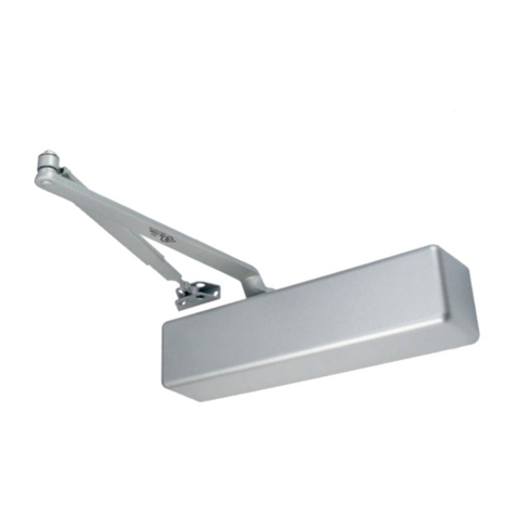
  9. Dorex 1901 Series User manual

Dorex 1901 Series User manual

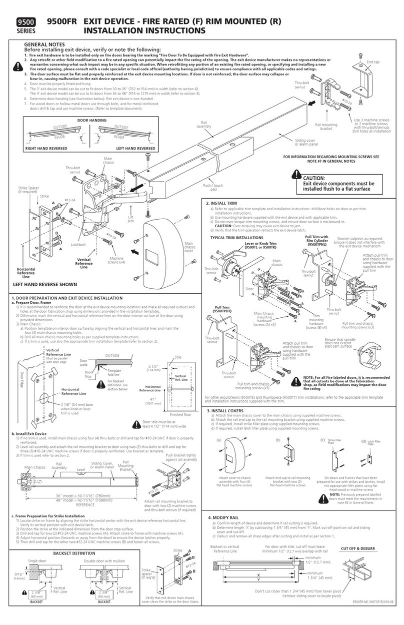
1DOOR OPENING DIMENSION A
85° 3-15/16 (100)
90° 3-3/8 (86)
2-1/2 (64)
100°
1-3/4 (44)
110°
Hin
g
e or Pivot
3-3/8
3/8
(9.5)
3/4
(19)
#7
7/32″
1/4-20
Metal Wood
2-1/8
(54)
(176)
(70)
(282.6) (282.6)
(86) (86)
2-1/8
(54)
Hin
g
e or Pivot
3-3/8
Dimensions
POWER
ADJUSTMENT
A
POWER
ADJUSTMENT
A
11-1/8
2-3/4
9/16
(14.3)
6-15/16
11-1/8
9/16
(14.3)
9/16
(14.3)
9/16
(14.3)
Inches
(mm)
(176)
6-15/16
3/4
(19)
3/8
(9.5)
DOOR CLOSER INSTALLATION
3DOOR CLOSER MOUNTING
HINGES SIDE
HINGES SIDE
On Fire Doors use
machine screws (a)
with sexnut (i)
Screws (a) or (b)
x 4
Screws (a) or (b)
x 4
RIGHT HAND
REVERSED (RHR)
LEFT HAND
REVERSED (LHR)
Speed adjusting valves must be positioned away from the
hinges side of the door.
C
L
C
L
Installation Instructions
1901-CSA, 1901-CSANHO
CUSHION STOP ARM (WITH / WITHOUT HOLD OPEN)
Select required door opening angle, then the mark the four (4) door closer mounting
holes center locations using measurements from the table. Mark the five (5) hole
locations on the inside frame (soffit) to mount the parallel bracket. Pre-drill 7/32"
holes for wood screws or drill and tap for 1/4-20 for machine screws.
Incorrect installation or adjustment could
cause damage or injury.
Read and follow instructions carefully.
Left hand door shown,
reverse measurements for
Right hand door application.
Right hand door shown,
reverse measurements for
Left hand door application.
1901-CSA-INST 2020/09 1/2
For correct door closer operation, the door closer and parallel arm must be level through out the full door opening.
If not, the misaligned part will be subject to bending, distortion and friction that will affect the door closer operation and usefull life.
2PARALLEL BRACKET CUSHION STOP CONFIGURATION
Configure the arm stop based on door closer installation (see Step 3) as indicated BEFORE installing bracket to the frame (see Step 4).
Insert ARM STOP into
hole as shown.
ARM
STOP FILLER
PLUG
BRACKET
⒠
BRACKET
A
RM
STOP
FILLER
PLUG Insert ARM STOP into
hole as shown.
⒠
FOR RIGHT HAND
REVERSED (RHR)
INSTALLATION
FOR LEFT HAND
REVERSED (LHR)
INSTALLATION
Screw Pack
(
Cush Arm
)
⒠
Machine 4
1
⒜
⒝
Wood 4
⒞
Wood 1
⒟
⒡
Machine 1
Through bolt sex nut
Filler Plug 1
Spacer Block 1
(g)
(i)
(h) 1
MOUNTING HARDWARE
4
COVER INSTALLATION
Install cover and attach with supplied screws
7
FREE
HOLD
HOLD-OPEN (STOP) ENGAGEMENT
COVER
SCREW (h)
CLOSER
PARALLEL
BRACKET
FOREARM
HOLD OPEN CONTROL
HANDLE (HOLD OPEN POSITION)
ARM SCREW (f)
MAIN ARM
5
DOOR CLOSER ADJUSTMENT
6
POWER ADJUSTMENT CHART
(- )
TURN CLOCKWISE
TO INCREASE POWER
(+)
DELAYED ACTION
Adjusting Valve
SWEEP
Adjusting Valve
LATCH
Adjusting Valve
BACK CHECK
Adjusting Valve
4mm
Wrench
DECREASE
INCREASE
Use 4mm Hex
Wrench
OPENING CYCLE
CLOSING CYCLE
DECREASE
INCREASE
FASTER
SLOWER
Screw
Power
Adjusting
Rotate
45°
45°
COVER
EXTERIOR
(SWING OUT)
INTERIOR
6 *
2
3
4
5
+ 12
1
0 (PRESET)
+ 4
- 4
- 8
+ 8
60" (1.52 m) 54" (1.37 m)
54" (1.37 m) 48" (1.22 m)
48" (1.22 m) 42" (1.07 m)
42" (1.07 m)
36" (0.91 m)
36" (0.91 m)
INSERT
Preload
Start with wrench
at this angle
TURN COUNTER-CLOCKWISE
TO DECREASE POWER
S
W
E
E
P
D
E
L
A
Y
O
P
E
N
I
N
G
B
A
C
K
C
H
E
C
K
L
A
T
C
H
FOR SPEED CONTROL ADJUSTMENTS REFER TO THE CONTROL
ADJUSTMENTS SUPPLIED WITH THE DOOR CLOSER
60 - 90 LBS
27 - 41 KG
33 - 65 LBS
15 - 30 KG
250 - 330 LBS
113 - 150 KG
85 - 140 LBS
38 - 63 KG
125 - 190 LBS
57- 86 KG
175 - 265 LBS
80 - 120 KG
ARM MOUNTING AND PRELOAD
8
1901-CSA-INST 2020/09 2/2
Installation Instructions
1901-CSA, 1901-CSANHO
CUSHION STOP ARM (WITH / WITHOUT HOLD OPEN)
PARALLEL BRACKET INSTALLATION
Screws (a) or (b)
Screws (c) or (d)
Spacer Block (g)
4
RIGHT HAND REVERSED
(RHR) INSTALLATION
LEFT HAND REVERSED
(RHR) INSTALLATION
POWER
Adjusting
Screw
Use wrench at lower shaft, rotate shaft 45° towards
the hinge side of the door as shown below, then
install arm on top shaft and secure with screw (f).
Hinge
Side
DOOR CLOSER
SIZE / POWER
REQUIRED
No. OF FULL TURNS
OF POWER ADJUSTING
SCREW REQUIRED
MAXIMUM
DOOR
WEIGHT
MAXIMUM DOOR LEAF SIZE
—
—
5 lbs
Opening
* Due to parallel installation, when adjusted to maximum power (Size 6),
the actual door closing force will be reduced to the equivalent of Size 5.
CAUTION! Do not turn speed adjustment valves more than
four (4) full turns counter clockwise from the fully closed
position or an oil leak will result.
A quarter turn on the HOLD-OPEN CONTROL HANDLE engages or
disengages hold-open. If handle does not engage properly, check and
correct the parallel arm level.

This manual suits for next models

2

Other Dorex Door Opening System manuals
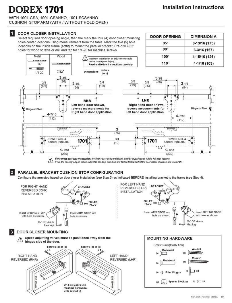
Dorex 1701 User manual

Dorex

Dorex 1701 User manual

Dorex 8500 Series User manual

Dorex

Dorex 8500 Series User manual

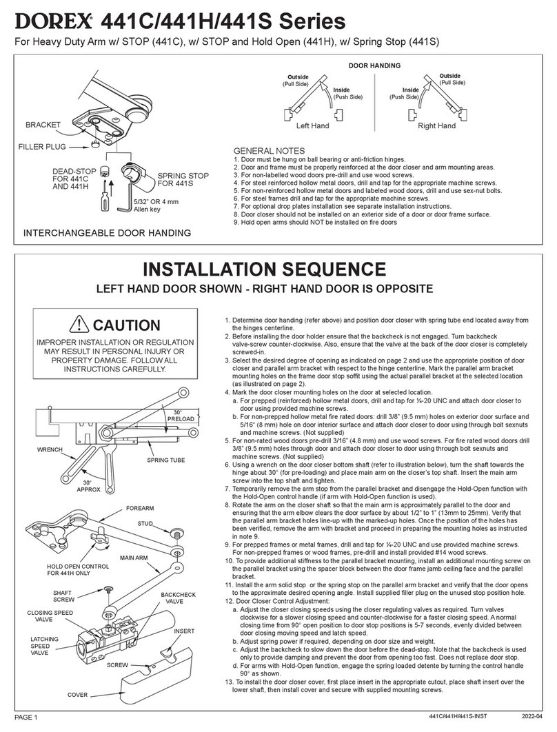
Dorex 441C Series User manual

Dorex

Dorex 441C Series User manual

Dorex 441 User manual

Dorex

Dorex 441 User manual

Dorex DX2 PC User manual

Dorex

Dorex DX2 PC User manual

Dorex 1701 Series User manual

Dorex

Dorex 1701 Series User manual

Dorex DX2 PW User manual

Dorex

Dorex DX2 PW User manual

Dorex 1901 User manual

Dorex

Dorex 1901 User manual

Dorex 9500 Series User manual

Dorex

Dorex 9500 Series User manual

Dorex 1900 Series User manual

Dorex

Dorex 1900 Series User manual

Dorex 8500 Series User manual

Dorex

Dorex 8500 Series User manual

Dorex DX KA User manual

Dorex

Dorex DX KA User manual

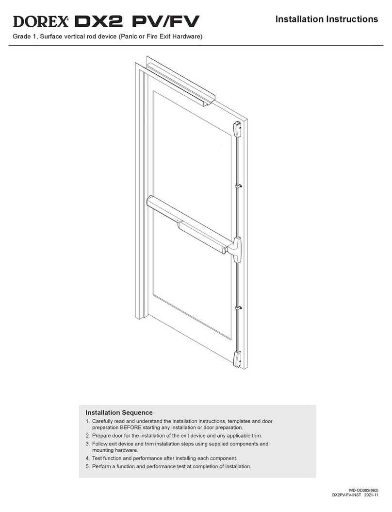
Dorex DX2 PV User manual

Dorex

Dorex DX2 PV User manual

Dorex 9500 Series User manual

Dorex

Dorex 9500 Series User manual

Dorex DX1 PV/FV User manual

Dorex

Dorex DX1 PV/FV User manual
Popular Door Opening System manuals by other brands

ECO Schulte ECO EF Assembly instruction

ECO Schulte

ECO Schulte ECO EF Assembly instruction

Global Automatics Premier-Slide 100 Technical manual

Global Automatics

Global Automatics Premier-Slide 100 Technical manual

Dorma ED800 J installation instructions

Dorma

Dorma ED800 J installation instructions

EINHELL FH 70 operating instructions

EINHELL

EINHELL FH 70 operating instructions

B&D Roll-A-Door R1N installation instructions

B&D

B&D Roll-A-Door R1N installation instructions

Lamp AZ-AT230-HL Nstallation instructions

Lamp

Lamp AZ-AT230-HL Nstallation instructions

Yale YDC201 installation instructions

Yale

Yale YDC201 installation instructions

Siemens 3VA9137-0FK Series operating instructions

Siemens

Siemens 3VA9137-0FK Series operating instructions

Roger Technology H70/104AC Instruction and warnings for the installer

Roger Technology

Roger Technology H70/104AC Instruction and warnings for the installer

Auta 700105 manual

Auta

Auta 700105 manual

Link Controls CDO Series instructions

Link Controls

Link Controls CDO Series instructions

WSS SPRINT NOVA 80 Assembly and operating instructions

WSS

WSS SPRINT NOVA 80 Assembly and operating instructions

GEZE TS 5000 RFS KB manual

GEZE

GEZE TS 5000 RFS KB manual

tau 150SESP manual

tau

tau 150SESP manual

Dorma 8956 AF89 PD manual

Dorma

Dorma 8956 AF89 PD manual

BFT CLONIX1 Installation and user manual

BFT

BFT CLONIX1 Installation and user manual

D+H ZA 35-HS instructions

D+H

D+H ZA 35-HS instructions

FAAC 950N Installation

FAAC

FAAC 950N Installation

manuals.online logo
manuals.online logoBrands
  • About & Mission
  • Contact us
  • Privacy Policy
  • Terms and Conditions

Copyright 2025 Manuals.Online. All Rights Reserved.