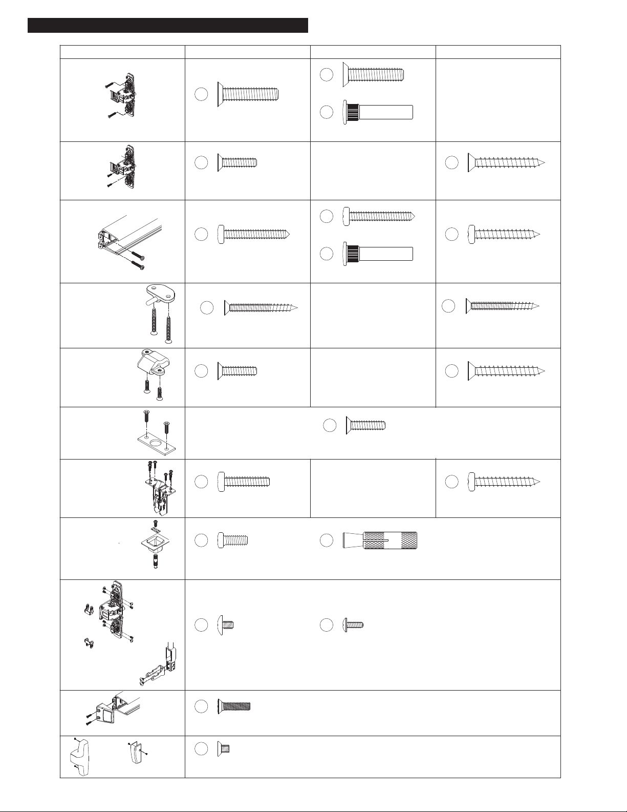
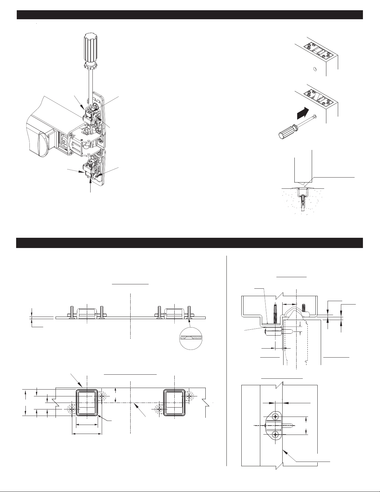
DOOR PREPARATION REFERENCE CHART
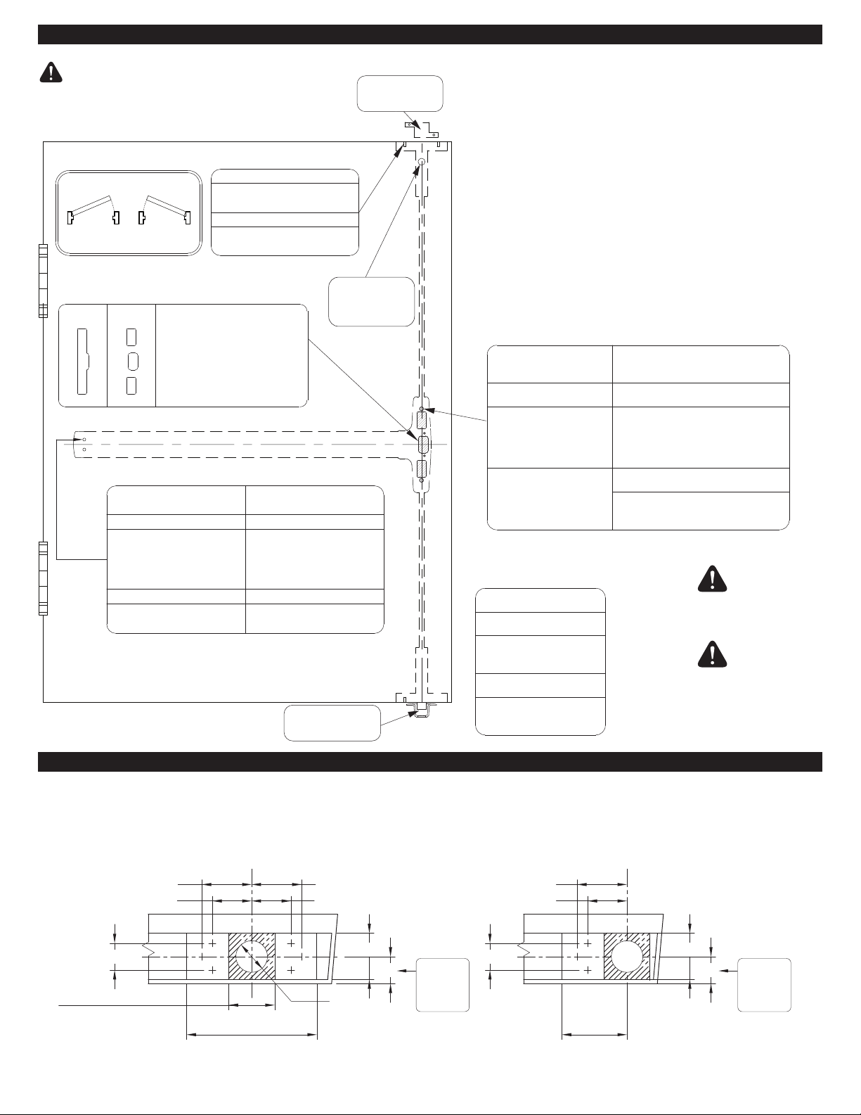
TOP & BOTTOM LATCH PREPARATION
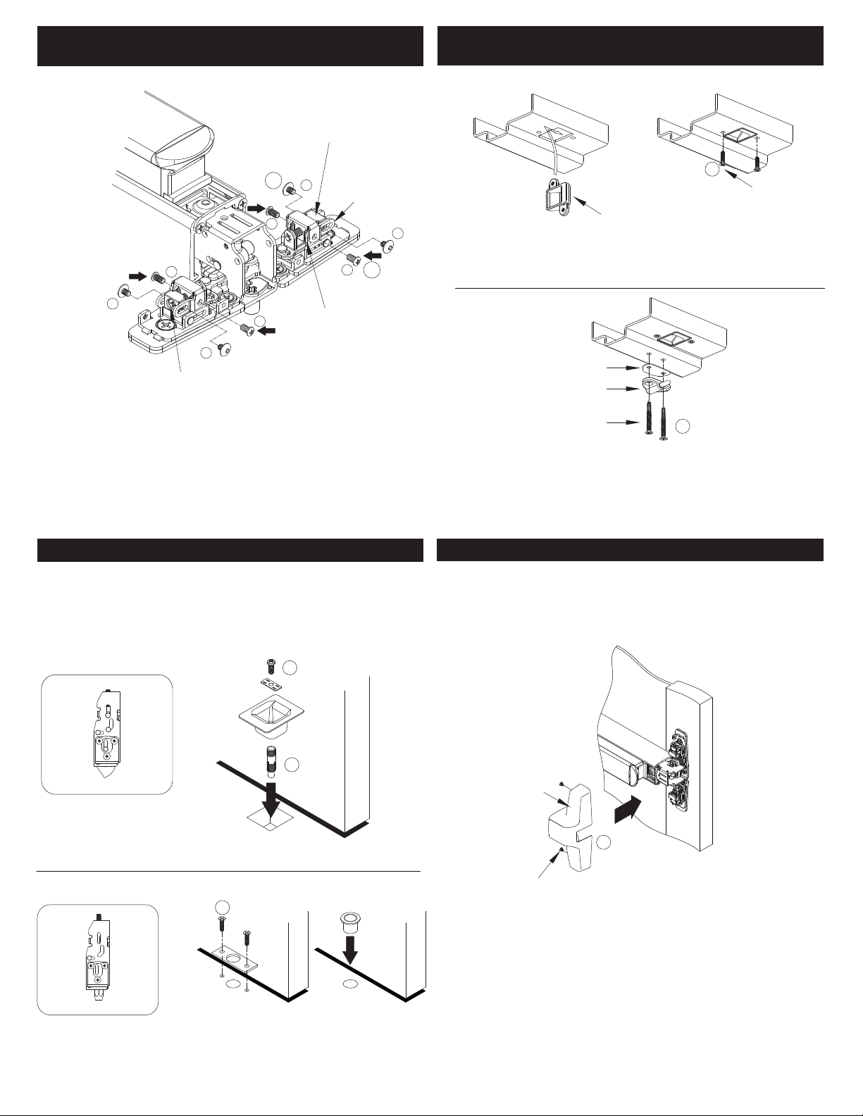
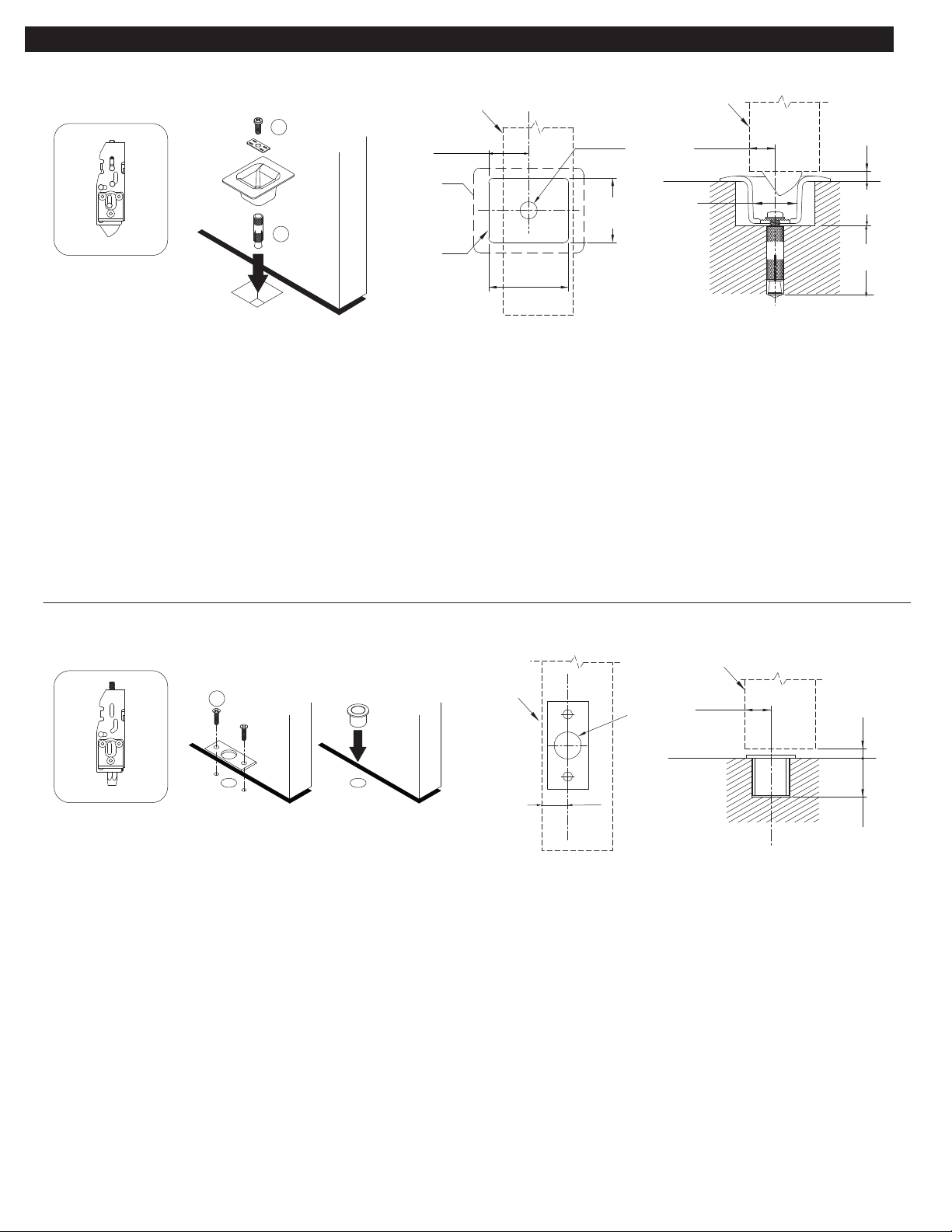
BOTTOM STRIKE
SEE PAGE 10
*PREPARE HOLES AFTER LOCK SIDE
OF DEVICE IS MOUNTED AND HINGE
SIDE OF DEVICE IS LEVELED
METAL
#25 DRILL
#10-24 TAP
END CAP BRKT. - 2 HOLES
SURFACE MOUNT
WOOD
¹/8" DRILL
PILOT 1" DEEP
¹³/32"
DRILL THRU
⁵⁄16" DRILL
(DEVICE SIDE)
¹³⁄32" DRILL
(OPPOSITE SIDE)
METAL
WOOD
SEX BOLTS
INSIDE
OUTSIDE
RHR LHR
LATCHES
RHR shown (LHR opposite)
of Device
L
C
#25 DRILL
#10-24 TAP
METAL
WOOD
¹/8" DRILL
PILOT 1" DEEP
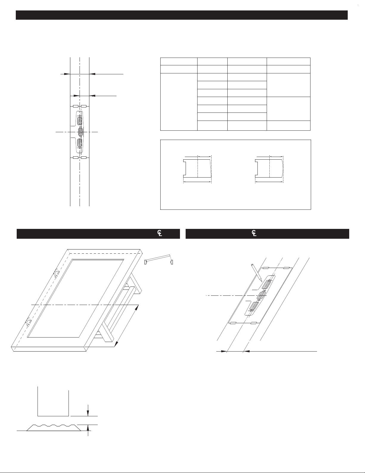
Vertical
LATCH RELEASE
PLUNGER HOLE
SEE PAGES 6 & 9
L
C
L
C
X
X
1⁵⁄8"
1⁹⁄32"
⁷⁄8"⁷⁄8"
1¹⁄2"1¹⁄2"
⁷⁄8"⁷⁄8"
1⁵⁄8"
1⁹⁄32"
1⁵⁄8"
1⁹⁄32"
Cut Out for Latchbolt 1¹⁄2"
METALMETAL
#7 DRILL
#¹/4"-20 TAP
WOOD
¹³/32" DRILL THRU (FOR SEX BOLTS)
¹/2" DRILL THRU (FOR TRIM)
⁵⁄16" DRILL INSIDE
¹³/32" DRILL (FOR SEX BOLTS)
¹/2" DRILL OUTSIDE (FOR TRIM)
SURFACE MOUNT
CENTER CASE - 2 HOLES
SEX BOLTS
OR WITH TRIM
CENTER CASE
2 HOLES
#25 DRILL
#10-24 TAP
WOOD
¹/8" DRILL
PILOT 1" DEEP
METAL
SURFACE MOUNT
N/A
of Device
L
C
Vertical
FOR DOOR PREPARATION REFERENCE ONLY.
Verify that this is the latest version of this document.
We recommend samples be used to verify
preparation before door / frame manufacturing.
Cut Out for Brackets
⁹⁄32" deep
Cut Out for Bracket
⁹⁄32" deep
4" 2"
SEE TRIM INSTALLATION INSTRUCTIONS,
TEMPLATES, OR DOOR PREPARATION
DOCUMENTS FOR DETAILS.
Fire Exit Hardware is to be installed on Fire Doors
bearing the marking “Fire Door to be equipped with Fire
Exit Hardware” Any retrofit or other field modification to
a Fire Rated opening can potentially impact the Fire
Rating of the opening.
IMPORTANT:
• Use supplied templates for field installations.
• Use door preparation documents for door/frame manufacturing.
• Door must be properly reinforced where the exit device chassis
and latches are mounted. The surface must be flush and flat
within ¹⁄16" (1.5 mm).
• Prepare the door and top and bottom door edges using the exit
device templates or door preparation and instructions.
• Prepare the exterior of door using the trim template or door
preparation and installation instructions.
• All threaded holes require a minimum metal material thickness
of 0.125" (3 mm).
• We recommend samples be used to verify preparation before
mass door or frame manufacturing.
• NOT RESPONSIBLE for any physical or property damage due to
incorrect / improper preparation or installation.
TOP STRIKE
SEE PAGE 9
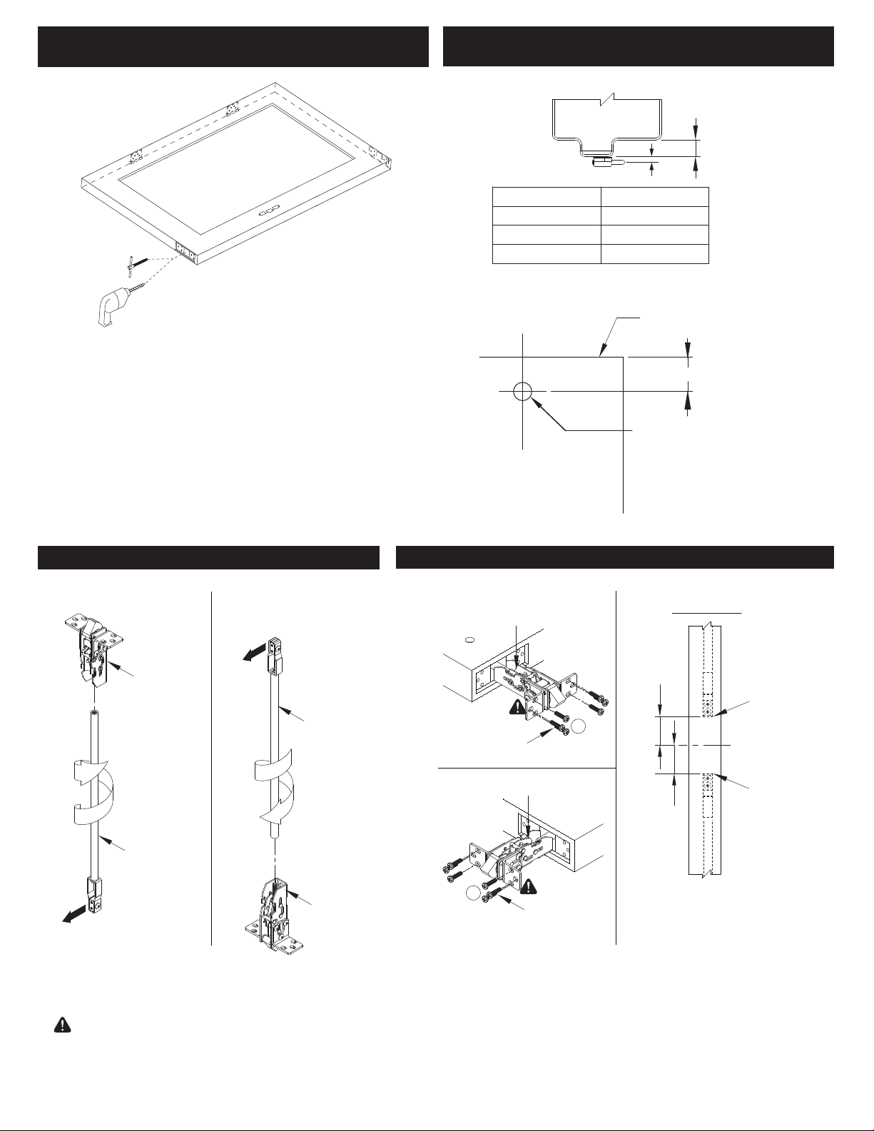
1" Dia.
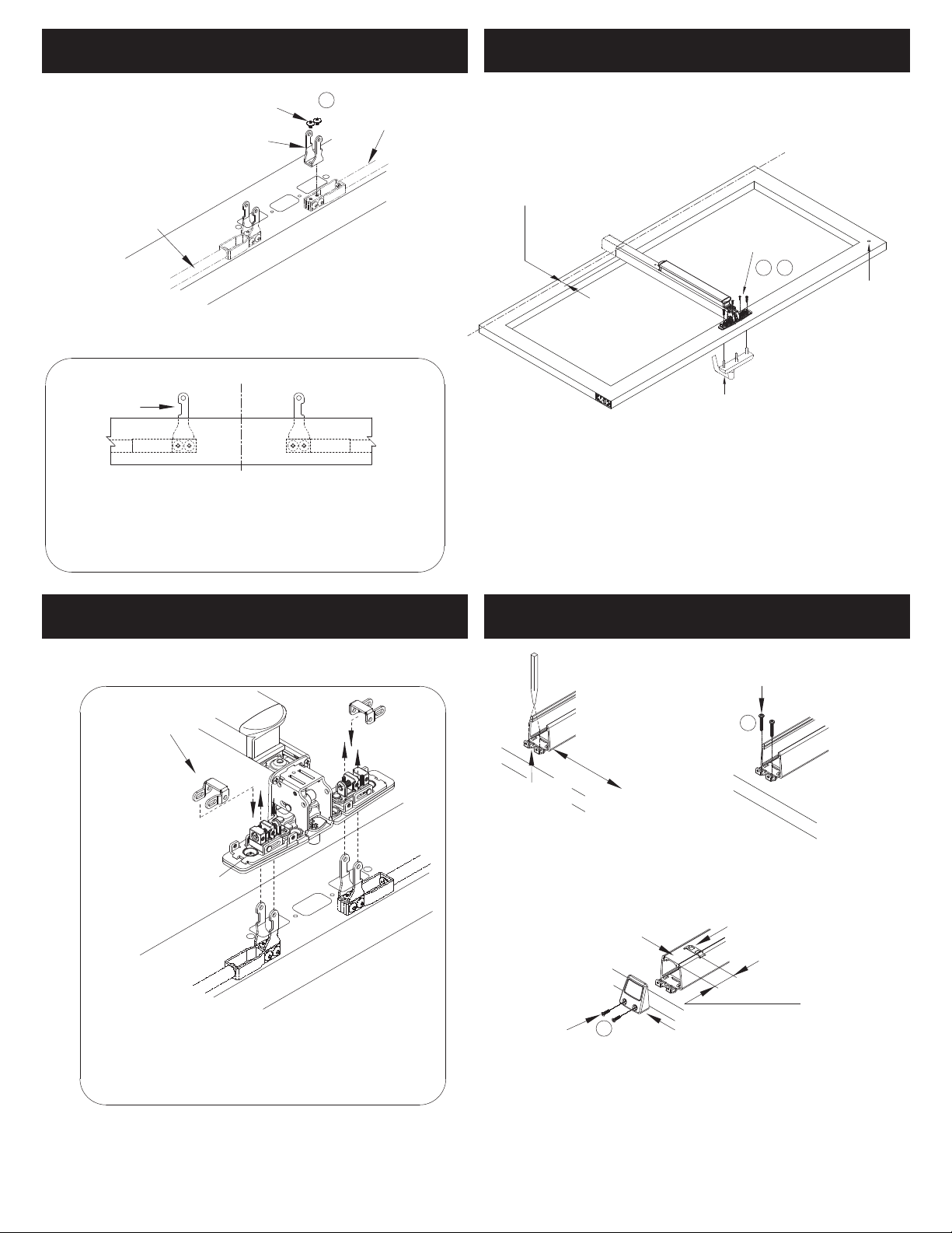
Prepare door bottom and top edge to accomodate required latch (see below) and vertical rods. Use the same backset (vertical centerline) used for the exit device center chassis.
It is recommended to install top and bottom latches using both pre-installed brackets as supplied.
Fire or Panic Exit Device
Both Brackets Installed
Panic Exit Device Only (optional)
One Bracket Installed
4 / 12
4¹⁄2" height from
door top edge
For vertical
rod passage
DOOR CUT-OUTS
CUT-OUT ON DEVICE
SIDE ONLY. 1³⁄8" DEEP
.
Consult template or
door preparation for:
- Metal door
- Wood Door
WOOD METAL
Constant
dimension
for all door
thicknesses.
Constant
dimension
for all door
thicknesses.