manuals.online logo
Brands
  1. Home
  2. •
  3. Brands
  4. •
  5. Dorex
  6. •
  7. Door Opening System
  8. •
  9. Dorex 1901 User manual

Dorex 1901 User manual

REGULAR MOUNT
(PULL SIDE)
TOP JAMB MOUNT
(PUSH SIDE)
PARALLEL MOUNT
(PUSH SIDE)
Latching
(F) Faster
(S) Slower
Backcheck
(–) Softer
(+) Harder
F
S
F
S
_
+
1
2
3
Closing
(F) Faster
(S) Slower
PARALLEL ARM INSTALLATION
CLOSER MOUNTED ON DOOR ON PUSH SIDE
This drawing shown is RIGHT HAND DOOR, for LEFT HAND DOOR install opposite
Page 1
SPRING POWER ADJUSTMENT
SPRING POWER SIZE TURNS
REQUIRED
5 lb-f*
8.5 lb-f*
Factory Preset
8 TURNS CCW
4 TURNS CCW
0 TURNS
1
2
3
4
5
6
8 TURNS CW
12 TURNS CW
4 TURNS CW
1901-ARMF-INST 2021-01
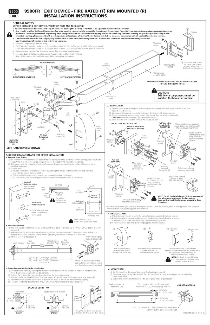
INSTALLATION INSTRUCTIONS
DOOR HANDING
SPRING POWER ADJUSTMENT CONTROL RANGE
PULL
SIDE
PULL
SIDE
PUSH
SIDE
PUSH
SIDE
LEFT
HAND
DOOR
RIGHT
HAND
DOOR
Refer to installation instructions supplied with door closer for more details
DOOR CLOSER INSTALLATION
1. Refer to installation instructions supplied with door closer.
2. Adjust spring power to match door size as indicated in chart on page 1.
3. Mount door closer on door using dimensions for the selected door opening
angle, with speed control valves facing away from the hinges.
4. Mount parallel arm bracket on frame stop soffit using dimensions for the
selected door opening angle.
5. Disconnect main arm from the forearm. Using a wrench on the door closer
bottom shaft rotate shaft about 45° towards the hinges and place main arm
on door closer top shaft and attach with screw.
6. Attach forearm (friction arm) shoe on the parallel arm bracket with two
machine screws. Position hold-open adjusting nut on top for right hand (RH)
door or bottom for left hand (LH) doors.
7. Close door, loosen hold-open adjusting nut (turn clockwise), and position
main arm parallel to the door surface and adjust length of threaded rod of
forearm to connect to the main arm. Secure forearm (friction arm) to main
arm with screw.
DOOR CLOSER ADJUSTMENTS
1. Refer to adjustment instructions supplied with door closer and pictorials on
page 1.
2. Adjust closing speed and latch speed so that the door closes for a 120° door
opening position within 6-7 seconds, evenly divided between sweep speed
and latch speed.
3. To adjust the hold-open position, open the door to the desired opening angle
and tighten the adjusting nut (turn counterclockwise) on the friction arm.
Close and open the door and verify that the hold open works.
4. Adjust backcheck if required.
COVER INSTALLATION
1. Place cover over door closer and attach with supplied screws.
2. Place shaft cover on the exposed door closer shaft.
Soffit
Parallel Arm
Bracket
Main
Arm
Page 4
LEFT
HAND
RIGHT
HAND
Soffit
Parallel Arm
Bracket
45° Preload
Main
Arm
Forearm
Preload 45°
Door opens to
the outside
Door opens to
the outside
INSTALLATION DIMENSIONS
OPENING
TO 120°
A
9-1/8
121°TO 180° 5-7/8
INCH mm
241
178
B
6-1/8
2-9/16
INCH mm
156
65
HIGHER
Clockwise (CW)
LOWER
Counterclockwise (CCW)
CCW : Counterclockwise CW: Clockwise
* pound (force)
Illustrations for reference only, actual door closer style and shape and arm may vary.
A
B
9/16
(14)
9/16
(14)
4-3/4
(120)
1-3/8
(35)
1-3/8
(35)
1
(25)
1
(25)
5/16”
(8)
11/16
(17)
11-1/8
(283)
3-3/8
(86)
INCH
(MM)
INCH
(mm)
Hold-Open
Adjusting Nut
Hinges
Centerline
DAS L BC
SPRING POWER ADJUSTMENT
WITH FRICTION HOLD OPEN ARM (1901-ARMF)
REGULAR ARM INSTALLATION
CLOSER MOUNTED ON DOORON PULL SIDE
This drawing shown is LEFT HAND DOOR, for RIGHT HAND DOOR install opposite
Page 2 Page 3
TOP JAMB INSTALLATION
CLOSER MOUNTED TOP JAMB ON PUSH SIDE OF DOOR.
This drawing shown is RIGHT HAND DOOR, for LEFT HAND DOOR install opposite
90°
90°
90°
90°
DOOR CLOSER INSTALLATION
1. Refer to installation instructions supplied with door closer.
2. Adjust spring power to match door size a indicated on chart on page 1.
3. Mount door closer on door using dimensions for the selected door opening
angle, with speed control valves facing the hinges.
4. Disconnect the forearm from the main arm. Place main arm on door closer top
shaft as shown in the illustration and attach with screw.
5. Mount forearm (friction arm) shoe on the door frame using dimensions for the
selected door opening angle. Position hold-open adjusting nut on top for right
hand (RH) door or bottom for left hand (LH) doors.
6. Close door, loosen hold-open adjusting nut (turn clockwise), position forearm
(friction arm) perpendicular to the door surface and adjust its length to connect
to the main arm. Secure friction arm to main arm with screw.
DOOR CLOSER ADJUSTMENTS
1. Refer to adjustment instructions supplied with door closer and pictorials on
page 1.
2. Adjust closing speed and latch speed so that the door closes within 6-7
seconds, evenly divided between sweep speed and latch speed.
3. To adjust the hold-open position, open the door to the desired opening angle
and tighten the adjusting nut (turn counterclockwise) on the friction arm.
Close and open the door and verify that the hold open works.
4. Adjust backcheck if required.
COVER INSTALLATION
1. Place cover over door closer and attach with supplied screws.
2. Place shaft cover on the exposed door closer shaft.
DOOR CLOSER INSTALLATION
1. Refer to installation instructions supplied with door closer.
2. Adjust spring power to match door size as indicated in chart on page 1.
3. Mount door closer on frame top jamb using dimensions for the selected
door opening angle, with speed control valves facing the hinges.
4. Disconnect the forearm from the main arm. Place main arm on door closer
bottom shaft and attach with screw.
5. Mount forearm (friction hold open arm) shoe on door using dimensions for
the selected door opening angle. Position hold-open adjusting nut on
bottom for right hand (RH) door or top for left hand (LH) doors.
6. Close door, loosen hold-open adjusting nut (turn clockwise), position
forearm (friction arm) perpendicular to the door surface and adjust its length
to connect to the main arm. Secure friction arm to main arm with screw.
DOOR CLOSER ADJUSTMENTS
1. Refer to adjustment instructions supplied with door closer and
pictorials on page 1.
2. Adjust closing speed and latch speed so that the door closes within
6-7 seconds, evenly divided between sweep speed and latch speed.
3. To adjust the hold-open position, open the door to the desired
opening angle and tighten the adjusting nut (turn counterclockwise)
on the friction arm. Close and open the door and verify that the hold
open works.
4. Adjust backcheck if required.
COVER INSTALLATION
1. Place cover over door closer and attach with supplied screws.
2. Place shaft cover on the exposed door closer shaft.
DA BC
Hold-Open
Adjusting
Nut
Hold-Open
Adjusting Nut
Forearm
Forearm
Main
Arm
Main
Arm
Preload
Preload
Preload
Preload
2 1/2" (63.5 mm)
Reveal
For reveals longer than
2 1/2" (63.5 mm) use
longer forearm rod
(sold separately)
Forearm Rod
RIGHT
HAND
LEFT
HAND
RIGHT
HAND
LEFT
HAND
Door opens to
the outside
Door opens to
the outside
1-7/16
(36)
7/8
(22)
9/16
(14)
9/16
(14)
Hinges
Centerline
DAS L BC
SPRING POWER ADJUSTMENT
5-1/2
(140)
1-3/4
(44)
11-1/8
(283)
A
INCH
(mm)
INSTALLATION DIMENSIONS
OPENING
101°TO 130°
A
7-3/32
131°TO 180°
INCHES mm
180
3-15/16 100
9/16
(14)
9/16
(14)
1-3/4
(44)
Hinges
Centerline
DA S L
BC
11-1/8
(283)
SPRING POWER ADJUSTMENT
A
1/2
(13)
1-3/4
(44)
5-3/8
(136)
INCH
(mm)
INSTALLATION DIMENSIONS
OPENING
101°TO 130°
A
7-3/32
131°TO 180°
INCHES mm
180
3-15/16 100
Frame Soffit

Other Dorex Door Opening System manuals

Dorex 441C Series User manual

Dorex

Dorex 441C Series User manual

Dorex DX2 PW User manual

Dorex

Dorex DX2 PW User manual

Dorex DX2 PC User manual

Dorex

Dorex DX2 PC User manual

Dorex 9500 Series User manual

Dorex

Dorex 9500 Series User manual

Dorex DX2 PV User manual

Dorex

Dorex DX2 PV User manual

Dorex DX1 PV/FV User manual

Dorex

Dorex DX1 PV/FV User manual

Dorex DX KA User manual

Dorex

Dorex DX KA User manual

Dorex 1701 User manual

Dorex

Dorex 1701 User manual

Dorex 1901 Series User manual

Dorex

Dorex 1901 Series User manual

Dorex 441 User manual

Dorex

Dorex 441 User manual

Dorex 9500 Series User manual

Dorex

Dorex 9500 Series User manual

Dorex 8500 Series User manual

Dorex

Dorex 8500 Series User manual

Dorex 1701 Series User manual

Dorex

Dorex 1701 Series User manual

Dorex 8500 Series User manual

Dorex

Dorex 8500 Series User manual

Dorex 1900 Series User manual

Dorex

Dorex 1900 Series User manual

Popular Door Opening System manuals by other brands

Automatic Technology Dominator Tempo ATS-2AM instruction manual

Automatic Technology

Automatic Technology Dominator Tempo ATS-2AM instruction manual

argenta PIVOTICA PRO 100 F0 manual

argenta

argenta PIVOTICA PRO 100 F0 manual

ECO Schulte EF BG Assembly instruction

ECO Schulte

ECO Schulte EF BG Assembly instruction

Crown Aut-o-doR 1502-1 GENERAL INSTALLATION, OPERATION, MAINTENANCE, and PARTS MANUAL

Crown

Crown Aut-o-doR 1502-1 GENERAL INSTALLATION, OPERATION, MAINTENANCE, and PARTS MANUAL

Dorma PORTEO Quick start manual

Dorma

Dorma PORTEO Quick start manual

Metaflex Medicare EI1 2.0 installation manual

Metaflex

Metaflex Medicare EI1 2.0 installation manual

Häfele XL Pocket Door Slide System Mounting instructions

Häfele

Häfele XL Pocket Door Slide System Mounting instructions

Aprimatic RAIDER installation instructions

Aprimatic

Aprimatic RAIDER installation instructions

GU DTN 80 operating instructions

GU

GU DTN 80 operating instructions

Dorma 7400 DS manual

Dorma

Dorma 7400 DS manual

CAME MI1010 quick start guide

CAME

CAME MI1010 quick start guide

Optex SW-1 installation manual

Optex

Optex SW-1 installation manual

Assa Abloy NORTON RIXSON 1600H Series installation instructions

Assa Abloy

Assa Abloy NORTON RIXSON 1600H Series installation instructions

Lamp FD30EX installation manual

Lamp

Lamp FD30EX installation manual

Sesamo Roto K3 Installation and Wiring

Sesamo

Sesamo Roto K3 Installation and Wiring

Akerstroms Sesam 500 Technical guide

Akerstroms

Akerstroms Sesam 500 Technical guide

Dictator DIREKT 200 Installation instruction

Dictator

Dictator DIREKT 200 Installation instruction

Assa Abloy SARGENT 351 installation instructions

Assa Abloy

Assa Abloy SARGENT 351 installation instructions

manuals.online logo
manuals.online logoBrands
  • About & Mission
  • Contact us
  • Privacy Policy
  • Terms and Conditions

Copyright 2025 Manuals.Online. All Rights Reserved.