manuals.online logo
Brands
  1. Home
  2. •
  3. Brands
  4. •
  5. Dorex
  6. •
  7. Door Opening System
  8. •
  9. Dorex DX KA User manual

Dorex DX KA User manual

Cover Plate
(Include Alarm Exit Module)
Emergency Exit Sign
(packed in cardboard tube)
SPECIFICATIONS:
9 Volt Battery
Alarm Exit Device
(DX1ALFR model shown)
Cylinder Lock Nut
COMPONENTS:
Voltage ..................................................... 12 to 24VDC,
12 to 24VAC
Current ...................................................... 0.2A
Battery ....................................................... 9V
Normally open inputs ................................ External inhibit (EI)
EMERGENCY EXIT ONLY
PUSH TO OPEN ALARM WILL SOUND
NOTE : 1. The Alarm Exit Module requires an RX or LM switch mounted in the exit device.
2. Choose battery or remote power for usage.
3. Alarm Kit can be used for DX1 or DX2 FR, FV, FC, FM and FW models.
DX KA Installation Instructions
Alarm Exit Device
1
WD-OD002(668)
DX-KA3-INST 2020-06
++
Route cable through hole and connect wires to power transfer
(see "POWER TRANSFER" instructions as needed).
NOTE: Alarm Exit Device does not contain dogging option. IMPORTANT: Before installing battery, make sure
transmitting cam is in OFF position.
Check if polarity
is correct Switch OFF
Position
- -
5/16"
5/8" Diameter
Drill 5/8"dia. wire access hole thru device side of door.
L
C
Cylinder
Lock Nut
Thread cylinder lock nut onto mortise cylinder.Make
sure to fasten down tight.
9 Volt
Battery Transmitting
Cam
1-1/4" Mortise
Cylinder
Power
Transfer
01. COMPLETE WIRING (IF REQUIRED) 02. INSTALL CYLINDER AND BATTERY
03. ATTACH WIRING TO TERMINAL BLOCKS ON ALARM EXIT MODULE
Power Supply
LM Switch
(Normally open contact)
NOTE: 1. The external inhibit (EI) option uses normally open (NO) dry access control
contacts to inhibit the AL.
2. Closing the access control contacts inhibits the AL. When the access control
contacts are re-opened, the AL re-arms with no delay.
3. All terminal inputs are not polarized.
(PS101/PS102 Class 2 Power Supply)
NO
COM
NC Violet
Gray
White
RX Switch
(Normally open contact)
EI
12VAC/24VAC
12VDC/24VDC
RX/LM
NO NC Yellow
Contacts RX/LM
terminal block
OR
Blue
COM Red
External Inhibit
(Normally open contact)
COM
NO NC
2
Insert cover plate back into the mechanism case.
NOTE: Be careful not to pinch cable when sliding
cover plate.
Contacts RX or
LM Switch
Contacts Power
Supply
Contacts External
Inhibit (EI)
Cover Plate End Cap
Bracket
After all wire connections are made and device checked for
operation, install the end cap bracket, end cap and label .
End Cap
End Cap
Screws
End Cap Bracket
Screws
Anti-Rattle Clip
04. INSTALL COVER PLATE 05. INSTALL MOUNTING BRACKET AND END CAP
Remove protective layer and stick Emergency Exit on door. NOTE: Length measured from push bar to cutoff line must not
be less than 9-3/4" long.
Pash Bar
9-3/4"
Cover Plate
(Flush to Push bar)
Cut off line
Emergency Exit Sign
Tape
06. MOUNT EMERGENCY EXIT SIGN 07. CUT DEVICE (IF REQUIRED)
3
NOTE: The default configuration setting for alarm sound is set for 5 minutes
before rearming.
Set switches No. 2 and 3 for auto reset alarm time.
Three setting options: 1.5, 3 or 5 minutes.
If switch No. 1 is off, AL device re-arms with no delay.
6. To change the battery.
A. Remove end cap and loosen or remove mounting bracket.
B. Remove cover plate.
C. Change Battery.
D. Reassemble.
MODE SELECT SWITCHES
Auto reset time
Rearm time
Option Function
Mode select
switches
End Cap
Bracket Screws
Cover Plate
On
AUTO RESET TIME
Switch No. 3
Switch No. 2
Factory settings shown
Minutes
On
WD-OD002(668)
DX-KA3-INST 2020-06
infinite
3
off
on
on
off
1-1/2
on
on
5
off
off
On
Auto reset time
Rearm time
Make sure polarity
is correct
-
End Cap
Screws
End Cap
End Cap
Bracket
9 Volt
Battery +
-
+
1. Insert the key into the cylinder and turn clockwise to arm unit. Rotate to initial position to remove key.
2. Arming time is of 15 seconds, during which the LED flashes green every 1.5 seconds.
3. A brief sound will indicate that the alarming time is complete. When armed the LED will flash red every 15 seconds.
4. Turn the key counterclockwise to disarm.
5. Changing the battery:
A beep will sound every 15 seconds to indicate that battery is low. This cannot be shut down by disarming the unit
and the sound will stop only when battery is changed.
LED Indicator Mortise Cylinder
{
OPERATION
OPTIONS
4

Other Dorex Door Opening System manuals
Dorex DX2 PW User manual

Dorex

Dorex DX2 PW User manual

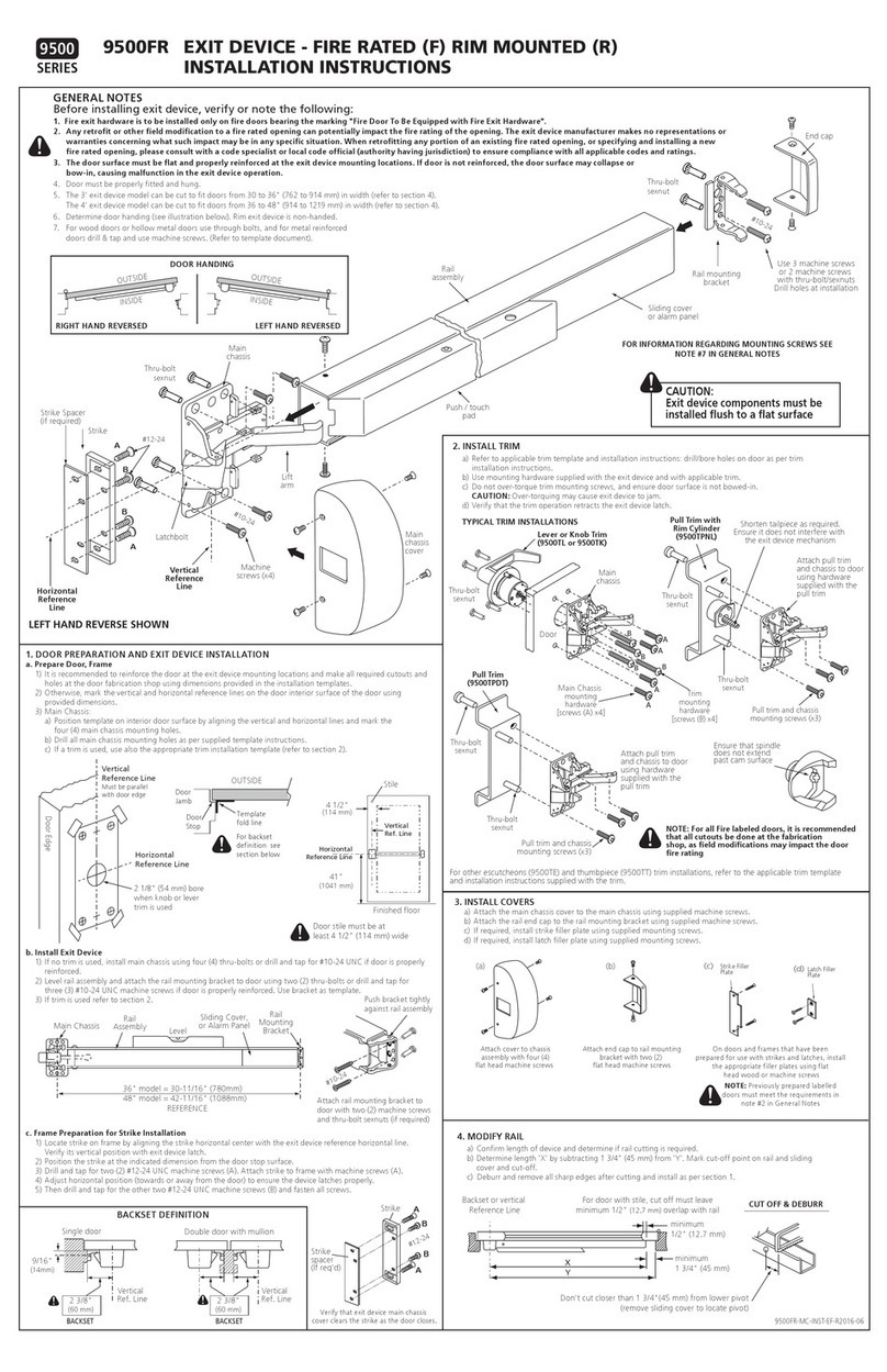
Dorex 9500 Series User manual

Dorex

Dorex 9500 Series User manual

Dorex 1701 User manual

Dorex

Dorex 1701 User manual

Dorex DX2 PC User manual

Dorex

Dorex DX2 PC User manual

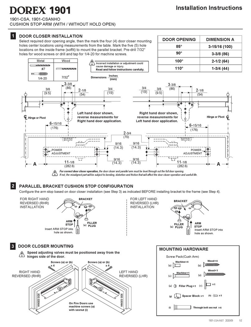
Dorex 1901 User manual

Dorex

Dorex 1901 User manual

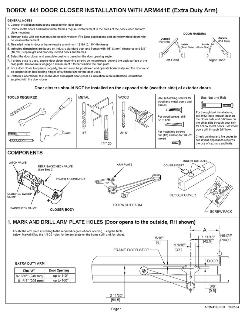
Dorex 441 User manual

Dorex

Dorex 441 User manual

Dorex DX1 PV/FV User manual

Dorex

Dorex DX1 PV/FV User manual

Dorex 8500 Series User manual

Dorex

Dorex 8500 Series User manual

Dorex 1900 Series User manual

Dorex

Dorex 1900 Series User manual

Dorex 1901 Series User manual

Dorex

Dorex 1901 Series User manual

Dorex 441C Series User manual

Dorex

Dorex 441C Series User manual

Dorex 8500 Series User manual

Dorex

Dorex 8500 Series User manual

Dorex 1701 Series User manual

Dorex

Dorex 1701 Series User manual

Dorex DX2 PV User manual

Dorex

Dorex DX2 PV User manual
Dorex 9500 Series User manual

Dorex

Dorex 9500 Series User manual

Popular Door Opening System manuals by other brands

Versus-Omega PENTA CITY 300 user manual

Versus-Omega

Versus-Omega PENTA CITY 300 user manual

Eco ECO EFR BG Assembly instructions

Eco

Eco ECO EFR BG Assembly instructions

BFT ELI-250 Installation and user manual

BFT

BFT ELI-250 Installation and user manual

CDVI IPV1 manual

CDVI

CDVI IPV1 manual

Eco SR Assembly instructions

Eco

Eco SR Assembly instructions

SECO-LARM Enforcer SD-C141S Catalogue

SECO-LARM

SECO-LARM Enforcer SD-C141S Catalogue

Yale 6116 Series installation instructions

Yale

Yale 6116 Series installation instructions

Dormakaba ED900 installation instructions

Dormakaba

Dormakaba ED900 installation instructions

Sesamo Puma Millenium Installation instruction

Sesamo

Sesamo Puma Millenium Installation instruction

Dorma 7300 DS manual

Dorma

Dorma 7300 DS manual

GEZE TS 5000 R-ISM/G quick start guide

GEZE

GEZE TS 5000 R-ISM/G quick start guide

CAMDEN CX-95S-DH installation instructions

CAMDEN

CAMDEN CX-95S-DH installation instructions

Hailo Libero 3.0 Configuration

Hailo

Hailo Libero 3.0 Configuration

Andersen SmoothControl+ installation guide

Andersen

Andersen SmoothControl+ installation guide

Eco SR BGX TS-61 G Assembly instruction

Eco

Eco SR BGX TS-61 G Assembly instruction

LCN COMPACT 6400 Series installation instructions

LCN

LCN COMPACT 6400 Series installation instructions

MAAX C6000 Series installation instructions

MAAX

MAAX C6000 Series installation instructions

Dorma PORTEO Assembly instruction

Dorma

Dorma PORTEO Assembly instruction

manuals.online logo
manuals.online logoBrands
  • About & Mission
  • Contact us
  • Privacy Policy
  • Terms and Conditions

Copyright 2025 Manuals.Online. All Rights Reserved.