6 / 16
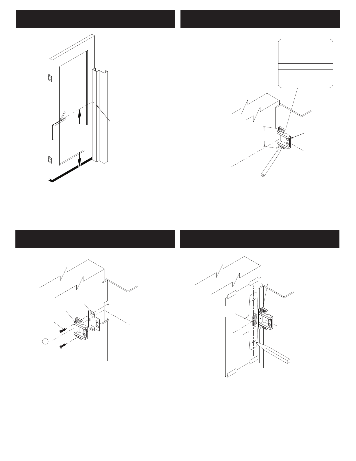
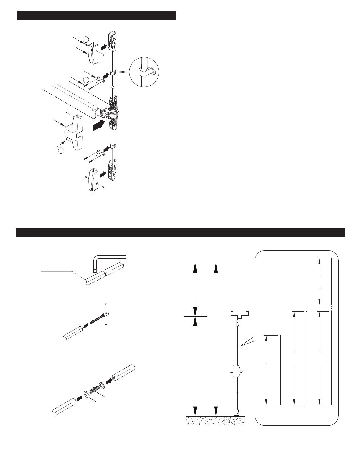
05. LOCATE TEMPLATES AND PREPARE DOOR 06. INSTALL TOP STRIKE AND SHIM
E
Install a screw through each slot.
Shim
Strike Screws
Strike Screws
Shim
Strike Screws
E
E
Shim
Strike Screws
E
DXAS106 DXAS203
Default for DX2PW
DXAS215
DXAS108
Default for DX2FW
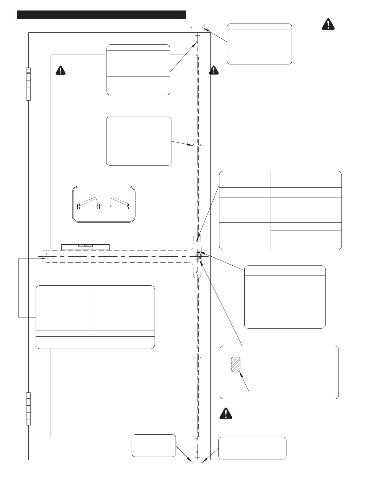
1. CAUTION: Prior to using supplied
templates, verify that the templates are
printed to full scale, by measuring some of
the indicated dimensions.
2. Position the center case template in line
with the marked horizontal and vertical
centerlines as shown. Tape the template on
the door and mark the cut-out and mounting
holes centers on the door’s interior side.
3. If trim is used, prepare the door exterior
side using the template and installation
instructions for that trim.
4. With door closed, fold the appropriate top
latch and strike template on the door stop
and inside door surface as shown, ensuring
the vertical centerline aligns with the exit
device vertical centerline. Tape template on
the door and frame, then mark the mounting
hole centers.
5. Fold the appropriate bottom latch and strike
template on the door bottom surface and
floor as shown, ensuring the vertical
centerline aligns with the exit device vertical
centerline. Tape template on the door and
floor and mark the mounting hole centers.
6. Drill and tap required holes and cut the
required cut-outs as indicated on page 4 of
the door preparation document.
7. Attach approprate center chassis strike as
per steps 2 and 3.
8. Attach approprate top strike as per step 6.
C
L
C
L
C
L
Top Latch
and Strike
Template
Bottom Latch
and Strike
Template
Center
Case
Template
0
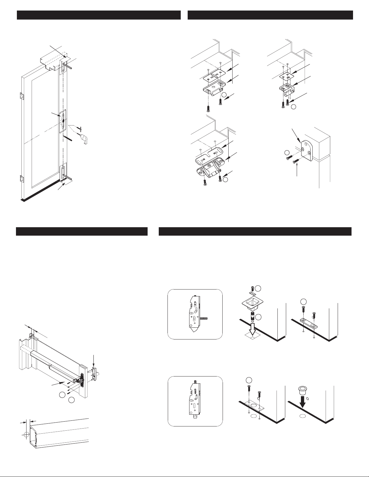
7. CENTER CASE INSTALLATION 08. INSTALL BOTTOM LATCH
Round Bottom Latch
E
DXAS226DXAS225
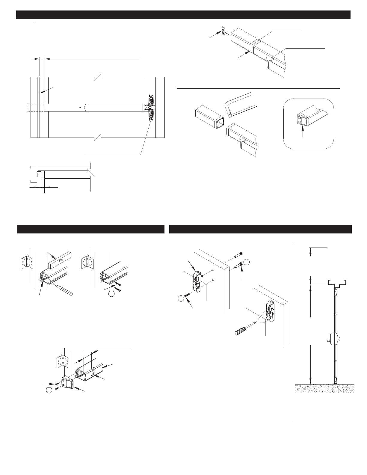
1. Verify if exit device rail length needs be shortened. If yes, refer to
step 9. The exit device requires a minimum clearance of 1-3/16”
between the frame’s door stop and the rail end (with end cover
removed). Otherwise install the exit device on door as required
with a trim or without a trim.
2. If exit device is used with a trim, attach the exit device and the
appropriate trim using instructions and hardware supplied with the
trim and the exit device.
3. If no trim is used and the exit device is surface mounted on the
door, used supplied mounting hardware as indicated on pages 2,
3, and 4.
4. Fire exit devices must be installed with through-bolts when
installed without a trim.
If a 5/8" diameter hole
is required for the
electrified exit device,
the hole must be
positioned as shown
E
F
1-3/16"
Center Case
Screws
Optional
Trim
7/16"
1. Following the marking of the bottom strike in step 5, prepare the floor for the appropriate
strike and mounting screws
2. If strike is installed on a threshold, provide the required holes and attach strike with
supplied screws.
3. Bottom strike can be installed after bottom latch installation to ensure a proper alignment.
Pullman Latch
(Defaut)
E
O
N
DXAS227
(Default)
DXAS224