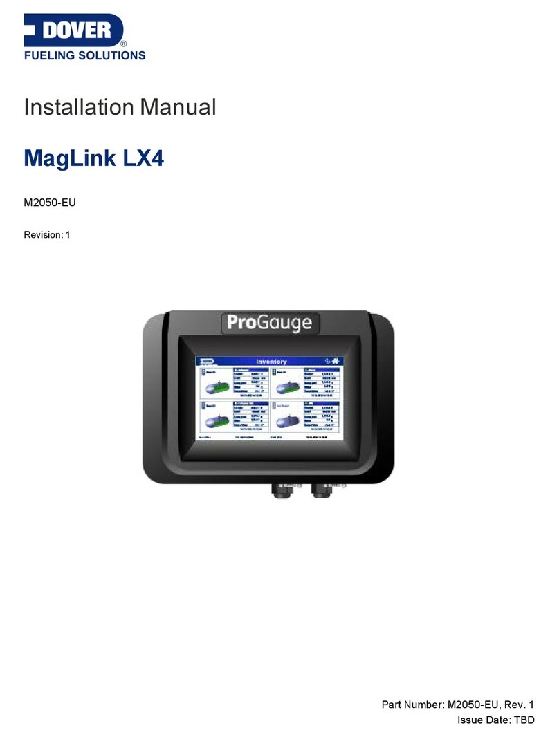
Dover MagLink LX4 User manual

ProGauge MagLink LX 4 Installation Manual
Part Number: M2050
Revision: 4
MagLink LX 4

Table of Contents
Section 1 Preface 4
Section 2 General Warnings 5
Section 3 Introduction 6
3.1 Safety Warnings 8
3.2 Information Panels 8
Section 4 General Indications 10
Section 5 Product Labels 12
Section 6 Installation 14
6.1 Installation Warnings 14
6.2 Installation Location 14
6.3 Electrical Connection 15
6.4 Installation Procedure 16
Section 7 Connections 18
7.1 Connection to the Intrinsically Safe XMT-SI and DMP-SI Probes 19
7.2 Connection to the XMT Explosion-proof Probe 20
7.3 Connection to the RF Receiver (for XMT-SI-RF) 21
7.4 Interface to Relay - Diagram of Connectors 22
7.5 DIP-Switch Configuration 24
7.6 Micro SD Card 25
7.7 Close and Start Up the Console 26
7.8 DB9 Connections to a Management System 26
7.8.1 FuelPOS/DIALOG Fuel Management System 26
7.8.2 GILBARCO Fuel Management System 27
7.8.3 Wayne Fusion Fuel Management System 27
Section 8 Maintenance 29
M2050 MagLink LX 4 Installation Manual | Dover Fueling Solutions 2

Section 1 Preface
Start Italiana S.r.l. has made every effort possible to see that this document is complete, accurate and
updated. With every revision of the console, the related information is added to the document. Start Italiana
S.r.l. reserves the right to make unannounced improvements and/or changes in the product and/or
associated programs. Start Italiana S.r.l. is not liable for damages of any kind, including those resulting in the
document, including typographical errors.
Making copies, citing quotes or other reproductions of all or part of this document is permitted only after
written consent of Start Italiana S.r.l.
Patents protect trademark or name.
Copyright 2022© Start Italiana S.r.l. – All rights reserved
M2050 MagLink LX 4 Installation Manual | Dover Fueling Solutions 4

Section 2 General Warnings
Carefully read the instructions in this manual before you do the installation procedures.
Only approved persons are permitted to install this equipment and configure the console.
The manufacturer is not responsible for operations that are not included in this manual.
The manufacturer is not liable in regards to competent bodies for changes to the equipment and software
that are not approved.
In case of failure or defect, refer directly to an authorized service provider or manufacturer.
The manufacturer is not liable for injury and/or damage to persons and/or property and/or pets caused by the
failure to obey safety instructions.
All approved personnel must know all safety requirements in this manual, the configuration manual and the
user manual.
Refer directly to an approved service provider or manufacturer for questions about the operation of the
equipment.
IMPORTANT: You must read and obey all safety instructions in this manual before you use
this equipment.
WARNING: Incorrect use of this equipment that does not agree with the
instructions in this manual can cause a risk to safety.
IMPORTANT: If a replacement power supply cable is necessary, use an applicable, approved
ELBZ/7 type power cord. Do not use another type of power cable.
M2050 MagLink LX 4 Installation Manual | Dover Fueling Solutions 5

Section 3 Introduction
This manual was prepared in accordance with IEC 82079-1 standards. “Preparation of instructions for use -
Structuring, content and presentation - Part 1: General principles and detailed requirements and according to
the ATEX Directive 2014/34/EU concerning equipment and protective systems intended for use in potentially
explosive atmospheres."
This manual gives all necessary information about the installation of the MagLink LX 4 console.
IMPORTANT: This manual must be used together with the related product manuals:
M2051 MagLink LX 4/LX Plus Configuration Manual
M2052 MagLink LX 4/LX Plus User Manual
You must install the console as shown in this manual, configure the console as instructed in
the M2051 MagLink LX 4/LX Plus Configuration Manual, and use the console in the field as
shown in the M2052 MagLink LX 4/LX Plus User Manual.
WARNING: This device must not be discarded with household waste. This
device is labeled in accordance with European Directive 2012/19/UE
concerning used electrical and electronic appliances (waste electrical and
electronic equipment – WEEE).
This guideline gives the methods for the return and recycling of used
electronic devices as applicable throughout the EU. To return your used
device, use the return and collection systems available to you.
The battery used in this device may present a risk of fire or chemical burn if
mistreated. Do not disassemble, heat above 50°C or incinerate.
The table that follows lists reference data of the manufacturer:
Data Description
Name START ITALIANA S.r.l.
Address
Via Natta 6
20823 Lentate Sul Seveso, (MB)
Italy
Telephone +39 0362 1581465
Fax +39 0362 1581464
Website www.startitaliana.com
e-Mail [email protected]
M2050 MagLink LX 4 Installation Manual | Dover Fueling Solutions 6

INFORMATION: The units of measurement contained in this manual refer to a specified
selection by the user. Refer to the M2051 MagLink LX 4/LX Plus Configuration Manual for
more information on how to set units of measure.
M2050 MagLink LX 4 Installation Manual | Dover Fueling Solutions 7

3.1 Safety Warnings
This manual contains many important Safety Alerts. There can be a risk of injury or damage to property if you
do not obey these alerts. The panels below show the types of safety warnings that can be seen and how
each is specified.
DANGER: Indicates an immediately hazardous condition that, if not prevented, will
result in death or serious injury.
WARNING: Indicates a possibly hazardous condition that, if not prevented, could
result in death or serious injury.
CAUTION: Indicates a possibly hazardous situation that, if not prevented, could
result in minor or moderate injury.
NOTICE: Indicates important information not related to hazards. A condition that, if not
prevented, can result in property damage.
SAFETY INSTRUCTIONS: Indicates instructions and procedures related to safety or
gives the location of safety equipment
3.2 Information Panels
NOTE: This panel gives more information about an instruction or procedure.
IMPORTANT: This panel contains special information that is important and must be read and
obeyed.
M2050 MagLink LX 4 Installation Manual | Dover Fueling Solutions 8

REMINDER: This panel shows information that has been given before in the manual that is
important to show again.
TIP: A step or procedure that is recommended to make another step or procedure easier.
INFORMATION: This panel shows references to more information in other sources.
READ CAREFULLY: This panel points to information that must be fully read and understood
before doing the procedure(s) that comes after.
M2050 MagLink LX 4 Installation Manual | Dover Fueling Solutions 9

Section 4 General Indications
The MagLink LX 4 console is shipped in a cardboard box (L 450 x H 300 x D 200 [mm]) and includes the
components as follows:
lMagLink LX 4 console
lConnection cable (220 V AC with Schuko plug)
lQuality control certification checklist
lUser manual, installation manual and web configuration manual
Weight of the console with its carton: 2 kg.
The table below shows the primary technical characteristics of the console:
Element Characteristic
Display Display TFT 7inch
Dimensions 155 x 88 [mm]
Console
Dimensions
· Width 267 mm
· Height with cable: 215 mm
· Depth 80 mm
The illustration below shows the ports and connections on the bottom of the console:
Make sure that the power cable is correctly installed. Put the Power Switch to the on ("I") position to supply
power to the console.
Put the Power Switch in the off ("O") position to remove power from the console.
M2050 MagLink LX 4 Installation Manual | Dover Fueling Solutions 10

DANGER: The console can contain electrical power after it has been shut
down. To prevent electrical shock do not open the console to do service for a
minimum of two (2) minutes.
IMPORTANT: Wait a minimum of two (2) minutes before you supply power to the console
again after it has been put in the Off position. This will give the console time to fully shut down.
Element Description
USB For USB printer connection. It can also be used for firmware updates and back-up of
the console (Refer to the M2052 MagLink LX 4/LX Plus User Manual)
RJ45 For console configuration, and local network connections (Refer to the M2051
MagLink LX 4/LX Plus Configuration Manual )
RS232 Com 1 Serial port for connection to management systems (FCC/POS/DCD)
RS232 Com 2 Serial port for connection to management systems (FCC/POS/DCD)
Ground
connection
Ground connection of the internal Intrinsically Safe barrier. Use a dedicated
4.0 mm2copper cable to connect to the main ground lug in the electrical panel of the
station. This will prevent high voltages sent to the Intrinsically Safe wiring side if
there is an electrical fault in the power side.
M2050 MagLink LX 4 Installation Manual | Dover Fueling Solutions 11

Section 5 Product Labels
lName and address of the manufacturer
lCE marking with the Notified Body
lProduct Name
lThe "Caution" symbol (0434B of 01/2004), according to ISO 7000
lSerial number
lYear of production
lPower Supply(VAC and Hz)
lPower consumption (VA)
lOperating temperature (°C)
lIngress protection (IP grade)
lFuse rating
lIndication that inside there is intrinsically safe circuit
M2050 MagLink LX 4 Installation Manual | Dover Fueling Solutions 12

lName and address of the manufacturer
lEquipment Type (BRA-SI, BRA-SIP, or BRA-2SIP)
lATEX Reference number of the certificate
lATEX Marking: Ex II (1) G [Ex ia Ga] IIB
lSerial number
lElectrical data
M2050 MagLink LX 4 Installation Manual | Dover Fueling Solutions 13

Section 6 Installation
6.1 Installation Warnings
DANGER: Do not install the console in a hazardous area!
Flammable fumes can cause an explosion when mixed with air.
Dangerous areas can occur where there are gases or fumes.
The MagLink LX4 console is NOT explosion-proof.
WARNING: Only use fuses of 250 V - 1 A for input power.
WARNING: connect the Intrinsically Safe Ground connection of the console
to the earth system of the site. A possible explosion or fire can occur if
damage is caused to the intrinsic safety of the device and high voltages are
sent to the Hazardous Area.
6.2 Installation Location
Select a location for the console installation where weather cannot cause negative effects or damage to the
electrical circuits (high and low temperatures, high humidity, direct sunlight etc.).
NOTICE: Install the console in a place that is protected from moisture, direct sun, and
water splashes. The console should be installed indoors in a climate-controlled room.
CAUTION: The console must be installed in a safe area.
M2050 MagLink LX 4 Installation Manual | Dover Fueling Solutions 14

6.3 Electrical Connection
To make a connection to 220 VAC:
lDe-energize all power switches at the main electrical panel.
lMake sure to use the applicable connections to connect the console to the electrical panel.
lFor power connections, use a single-phase cable, a section of which is not less than 1.5 mm2and
one which is sufficiently protected. The power cord must comply with the standards IEC 60227 and
IEC 60245. The cable supplied with the console already complies with these regulations.
lMake sure the power plug is connected to the ground and protected against short circuits and
power surges.
lMake sure to connect the I.S. ground to the site's earth system. Use a dedicated 4.0 mm2copper
cable (see the illustration below).
.
lThe power cord must be easy to identify and must have easy access so it can be used to remove
power.
WARNING: There is high voltage within the console.
IMPORTANT: The electrical connection procedure must be done by approved personnel
only!
M2050 MagLink LX 4 Installation Manual | Dover Fueling Solutions 15

6.4 Installation Procedure
1. Remove the three (3) cover screws as shown in the illustration above.
2. Lift the cover carefully and disconnect the ribbon cable from the rear panel of the console as shown
in the illustration above. Put the cover and screws in a temporary safe location where they can be
found later and where the components cannot be damaged.
M2050 MagLink LX 4 Installation Manual | Dover Fueling Solutions 16

3. Attach the rear panel to a wall.
a. Select a location to attach the console to an indoor wall where it can be easily seen. Make
sure to keep sufficient access to the connection ports on the bottom of the console.
b. Hold the unit against the wall where it will be attached. There are four (4) mounting screw
holes in the unit (see the illustration above for the locations of the holes).
c. Use a pen to identify the screw hole locations on the wall.
d. Drill the holes at the screw hole location marks.
e. Tap the holes for an applicable screw size or put screw anchors in the hole.
NOTE: It is recommended to use size 6 Fischer wall anchors.
f. Attach the unit to the wall with the applicable screws.
M2050 MagLink LX 4 Installation Manual | Dover Fueling Solutions 17

Section 7 Connections
The table that follows shows a list of the inner components of the rear of the console.
Component Description
1 Power Supply Unit (PSU) protection panel
2 BRA-2SIP barrier for connection to the DMP-SI-485 and XMT-SI-485 probes (8+8)
3 Four (4) Built-in Relays, Six (6) Inputs
M2050 MagLink LX 4 Installation Manual | Dover Fueling Solutions 18

7.1 Connection to the Intrinsically Safe XMT-SI and DMP-SI Probes
The table that follows shows the wiring connections between the XMT-SI and DMP-SI Probes and the LX
4Console:
Connection Specification
MR1 Barrier Input
MR3
Safety Barrier Input (up to eight [8] probes)
Red (+ 12V) - Terminal 1
Brown (RS485A) - Terminal 2
Blue (RS485B) - Terminal 3
White (-0 V) - Terminal 4
MR4
Safety Barrier Input (up to eight [8] probes)
Red (+ 12V) - Terminal 1
Brown (RS485A) - Terminal 2
Blue (RS485B) - Terminal 3
White (-0 V) - Terminal 4
If a site installation has more than 16 probes/tanks you must use an external MagDirect barrier connected to
the console MR1 or CN7 (see below) terminal blocks. Each MagDirect barrier can hold up to eight (8) probes.
See the Wiring Diagram section for more information.
M2050 MagLink LX 4 Installation Manual | Dover Fueling Solutions 19

7.2 Connection to the XMT Explosion-proof Probe
You can install up to 32 XMT probes on CN7.
The XMT model explosion probes must be connected in parallel to the console and directly to the connector
CN7. It does not go through the intrinsically safe barrier (the barrier is not applicable in this installation).
The table that follows shows the wiring connections between the XMT Probes and the LX 4 Console main
board CN7 terminal block:
Connection Specification
CN7
White (-0 V) - Terminal 4
Blue (RS485B) - Terminal 3
Brown (RS485A) - Terminal 2
Red (+ 12V) - Terminal 1
M2050 MagLink LX 4 Installation Manual | Dover Fueling Solutions 20
Other manuals for MagLink LX4
3
This manual suits for next models
1
Table of contents
Other Dover Controllers manuals

Dover
Dover All-Flo PSG 72000-00 Owner's manual

Dover
Dover Hydro Connected Total Eclipse User manual

Dover
Dover DMM-0200 Specification sheet

Dover
Dover Petro Vend FSC3000 User manual

Dover
Dover DESTACO ROBOHAND DRG Series User manual

Dover
Dover MagLink LX4 User manual

Dover
Dover All-Flo PSG 72100-00 Owner's manual
Dover
Dover NEPTUNE PSG NEP-131906 Owner's manual

Dover
Dover HYDRO Multi-Washer 3000 Series User manual

Dover
Dover Markem-Imaje LASER 7031 Quick start guide