manuals.online logo
Brands
  1. Home
  2. •
  3. Brands
  4. •
  5. Draper
  6. •
  7. Projector Accessories
  8. •
  9. Draper SL4 Manual

Draper SL4 Manual

Copyright © 2001 Draper, Inc. Form SLi01 Printed in U.S.A.
Caution:
ÀRead instructions completely before proceeding.
ÁPerform Pre-Installation Testing Procedures (page 2) before beginning
to install unit.
ÂFollow instructions carefully. Installation contrary to instructions
invalidates warranty.
Ão not obstruct operation of Scissor Lift with fingers or any object.
Serious injury or damage could result.
ÄScissor Lift is designed to accommodate ceiling suspended equipment.
Equipment should not be allowed to rest on optional ceiling closure
during operation. (Refer to section titled “Installing Projector.”)
ÅEntire bottom of unit must be unobstructed to permit proper operation.
Sufficient clearance must be allowed below projector or optional ceiling
closure: 4' for Model SL4, 5' for Model SL5, etc.; 11' for Model SLX11,
12' for Model SLX12, etc.
ÆUnit must be installed level (use a carpenter’s level).
ÇUnit operates on 110v AC 60 Hz. current.
Note: Unit has been thoroughly inspected and tested at factory and found
to be operating properly prior to shipment.
Planning
ÀBased on screen location and projector specifications, determine proper
position for projector installation.
ÁConfirm that there is adequate space for installation and operation.
Minimum clearance above ceiling level varies according to Scissor Lift
model, plus height of projector, optional mounting bracket, optional ceiling
closure, and optional plenum rated housing.
ÂArrange to provide service access to the unit.
As Soon As Scissor Lift Arrives
ÀOpen carton and inspect for damage.
ÁLocate the following parts:
A. The unit itself
B. Controls
C. Any optional equipment
Âo the Pre-Installation Testing Procedure (see page 2).
Pre-Installation Testing Instructions
This Scissor Lift was extensively tested and in perfect condition when it left
our plant. To make sure that it arrived in the same condition, please use the
following procedure to test the unit prior to installation.
raper does not accept back charges for labor. Make sure that this unit is
operating satisfactorily before installation.
anger! The scissor mechanisms can exert over 350 pounds of force. o not
insert any body parts or other objects into this unit while power is connected.
ÀRemove the unit from the outer carton.
ÁTemporarily suspend the unit in order to proceed with pre-installation
instructions.
ÂYou will find an operating switch that can be temporarily connected to
switch wires by use of a telephone type connector.
ÂAlso, you will find a temporary power plug connected to this unit.
ÃMake sure that the switch is in the off position and plug the unit into a
110v AC source. Caution: o not touch any exposed wires while the unit is
plugged in.
ÄUse the switch to move the bottom pan down. The pan will automatically
stop when it reaches the “show” position. Remove packing inserts.
Installation/Operating Instructions
SL & SLX Scissor Lift Video Projector Lift by Draper
ÆCycle the unit in both directions until you are satisfied the unit is operating
properly. If for any reason the unit does not seem to operate properly, call
raper, 765-987-7999. Do not proceed with installation.
ÇIf the unit has been ordered with the remote control option, again verify
operation of the unit by use of the hand held transmitter. If for any reason
the unit does not seem to operate properly, call raper, 765-987-7999. Do
not proceed with installation.
ÈIf the unit is operating satisfactorily, remove and discard the temporary
plug. EEP THE SWITCH!
ÉProceed with the installation, referring to instructions supplied.
Hanging Unit
The Scissor Lift may be installed in a variety of ways; recessed above the
ceiling, or suspended below the ceiling. The lift is supported by four ½"
threaded mounting rods. If ceiling recessed, the entire unit (including the
projector) should set approximately 1½" above the finished ceiling in its
“stored” position. The threaded rods should pass through the corner mounting
flanges and be secured by nuts above and below. Use a thread locking
compound such as Loc Tite #242 (provided). The unit should then be guy
wired or blocked to prevent swinging.
All installations should observe the following guidelines:
ÀInstaller must ensure that all fasteners and supports are of adequate
strength to securely support Scissor Lift and projector.
ÁFastening methods must be suitable for mounting surface, and securely
anchored so that vibration or abusive pulling on unit will not weaken
installation.
ÂUnit should be level, with weight shared more or less equally by all four
threaded mounting rods.
ÃBottom of unit must be unobstructed after installation. Sufficient clearance
must be allowed below projector or optional ceiling closure: 4' for Model
SL4, 5' for Model SL5, etc.; 11' for Model SLX11, 12' for Model SLX12, etc.
ÄAccess from above the unit, with enough clearance to remove the top
cover, should be provided in case service is required.
Åo not use unit to support adjacent ceiling, light fixtures, etc.
Æo not complete the ceiling below unit until electrical connections have
been completed and unit has been operated successfully.
ÇWe recommend that safety cables be attached to the Scissor Lift for added
security (a sound installation practice with overhead equipment).
Electrical Connections
Unit operates on 110v AC, 60 Hz. current.
Removing the top cover of the unit and opening the electrical box exposes
terminals for field connections. Unit is shipped with internal wiring complete
and control switch (es) pre-wired for Pre-Installation Testing Procedure. Wire
to connect unit to power supply should be furnished by installer. Connections
should be made in accordance with wiring diagram, and wiring should comply
with national and local electrical codes. All operating switches should be “off”
before power is connected.
Scissor Lift should be operated and checked prior to installing projector and/
or optional ceiling closure.
Optional Ceiling Closure for Scissor Lift
Scissor Lift by Draper, Inc. page of 4
Operation
When unit is first operated, be cautious! If unit fails to operate when the
toggle switch is flipped “down”, return switch to “off” and recheck electrical
connections before proceeding. Cycle unit down and up several times to
confirm satisfactory operation.
Standard Single Station Control—One, 12 volt toggle switch: moving 3-
position toggle switch to “down” position will start lift down. Moving toggle
switch to “up” will start lift up. When lift is in “show” position, travel will
automatically be stopped by factory set limit switches. Whenever switch is
placed in center “off” position, operation will stop. One, 12 volt key switch will
lower lift from “show” to “service” position.
Video Interface Control—This optional 12 volt control device allows the
Scissor Lift switch to control the operation of a raper motorized projection
screen via a relay.
Multiple Station Control—Optional, moves lift from “stored” to “show”
positions only. Each switching station has a three-button switch with “up”,
“down”, and “off” buttons. Lift starts up or down when appropriate button is
pressed, and may be stopped by pressing “off” button. Factory set limit
switches stop lift automatically when projector is in “show” position.
ey Operated Switch—If ordered, a single station, key-operated three
position (up/off/down) switch is available. Multiple Station Control required for
this option. Moves lift from “stored” to “show” positions only.
Infrared or Radio Frequency Remote Control—If ordered, a three-button
transmitter is provided, with “up”, “down”, and “stop” buttons. Unit starts up or
down when appropriate button is pressed, and may be stopped by pressing
“off” button. Factory set limit switches stop unit automatically when projector
is in “show” position. Multiple Station Control required for this option.
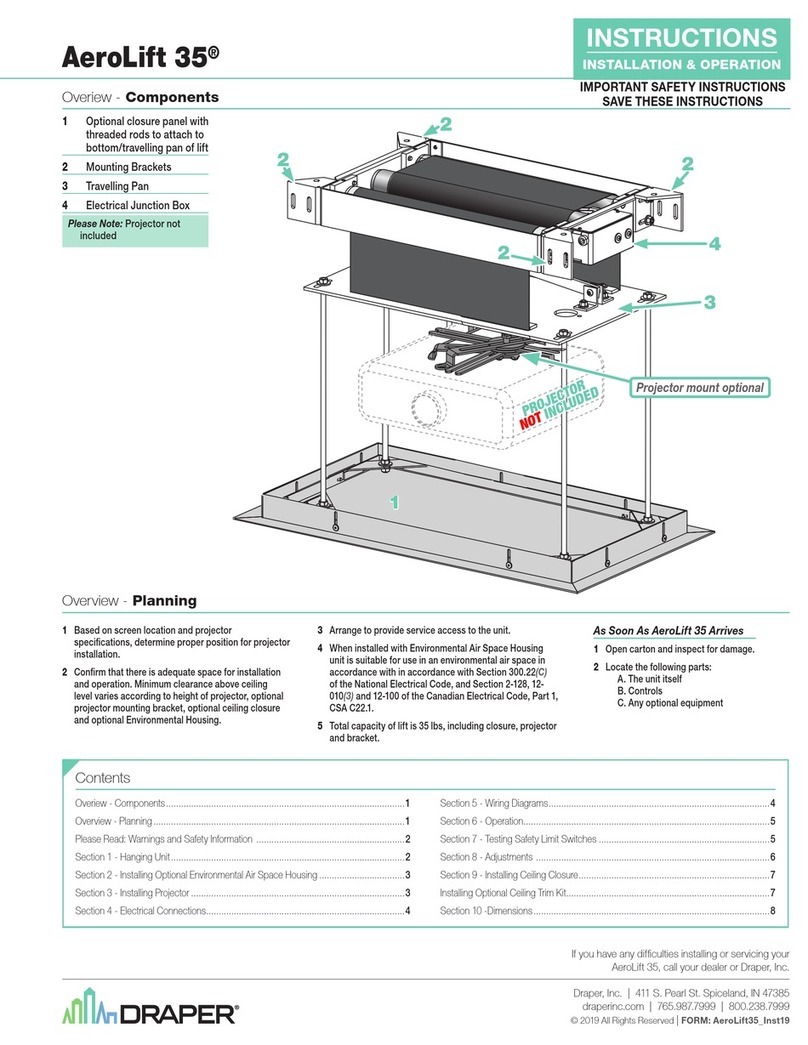
If you encounter any difficulties installing or servicing your Scissor Lift, call
your dealer or Draper, Inc. in Spiceland, Indiana, 765 987 7999, or fax
765 987 7142.
Installing Projector
epending on job conditions and projector, it may be easier to remove
optional ceiling closure panel before installing projector.
Generally, the video projector should be suspended from the bottom pan
according to projector manufacturer’s instructions and using recommended
standard ceiling mounting hardware (supplied by others).
The Scissor Lift has a grounded 110v AC, 60Hz power cord for projector
power supply. The power cord is laced down the back scissor and is “hot” at
all times.
Control cables should be laced through our Cable Management System. This
will ensure that cords do not become tangled and damaged during Scissor Lift
operation.
Unit and projection system should be operated, checked and adjusted as
necessary at this time.
After testing operations, the optional closure panel should be reattached. Be
sure to use Loc Tite, or other thread locking compound on the nuts.
NOTE: Immediately upon completion of the surrounding ceiling, units should
be operated to confirm that optional ceiling closure panel stops just short of
touching ceiling in closed position.
Warning: Keep fingers and other objects away from automatic ceiling closure
and scissor mechanisms when unit is operating. Serious injury or damage
could result.
Baked enamel ceiling closure
Ceiling closure frame
Trim strip
Ceiling tile
(by others)
Ceiling tile recessed by others
Trim strip
Ceiling tile
(by others)
Ceiling closure frame
Pan Closure
Ceiling Tile Closure
Installing Optional Ceiling Closure
Your Scissor Lift can be equipped with an optional ceiling closure system. To
install it:
ÀRemove closure and all mounting hardware from carton.
ÁThe optional ceiling closure can be mounted in either of the following
styles:
A. If ceiling tile is to be inserted in the closure, this may be done now, or
later when the rest of the ceiling is installed (permitting a better match). Cut
tile so that its overall dimensions are the same as (or slightly less than) the
closure panel. Attach to the closure panel with mastic.
B. Position one pre-cut aluminum tee along outside edge of panel so arm
extends under and rests on the panel (or tile if tile is being used). Be
careful not to compress the tile. rill three holes through rib of tee into
edge of panel and pop rivet into place.
C. Follow same procedure with remaining 3 tees.
NOTE: Since tees comprise part of exposed trim, care should be taken
to ensure accurate fit.
ÂAttach (2) labeled mounting angles to the corresponding holes in the
bottom pan with the supplied hardware.

ÃAttach other (2) labeled mounting angles at 90° to previous angles (right to
left) in the corresponding holes with the supplied hardware.
ÄAttach one of four
3
/
8
" threaded rods by passing the rod through one of the
four corner holes, in the angles and secure with nuts top and bottom.
Approximately ½" of rod should extend above grid.
ÅRun unit “up” until bottom pan stops at highest position. Mark position on
3
/
8
" rod that is even with ceiling level and cut rod to length (removing it from
pan if convenient). Cut remaining three rods to same length.
ÆRun unit “down” until bottom pan stops at “show” position. Secure all four
3
/
8
" rods to traveling pan in same fashion as first one.
ÇAttach closure to lower end of each
3
/
8
" rod using two remaining nuts on
each rod to firmly clamp fixtures on top of panel.
ÈRun unit “up” again to highest position. Measure distance by which panel
fails to reach required “closed” height for surrounding ceiling.
ÉRun unit “down” then readjust mounting of
3
/
8
" rods in traveling grid to raise
panel required distance.
NOTE: Rods should not extend more than 1" above the angles attached
to the pan. Cut extra rod off if necessary.
11 Test unit operation to confirm that panel will stop in closed position just
before touching ceiling.
Scissor Lift by Draper, Inc. page 3 of 4
Maximum
Lowering Retracted
Model istance Height
SL4 4' 8
1
/
8
"
SL5 5' 9
1
/
8
"
SL6 6' 10
1
/
8
"
SL7 7' 11
1
/
8
"
SL8 8' 12
1
/
8
"
SL9 9' 13
1
/
8
"
SL10 10' 14
1
/
8
"
SLX11 11' 13¾"
SLX12 12' 15¾"
SLX13 13' 15¾"
SLX14 14' 16¾"
SLX15 15' 16¾"
SL Series
SLX Series
Typical Installation Details
Space for projector's
ceiling mounting bracket
Space for projector
Optional ceiling
closure panel
See chart
(shown slightly lowered)
Pair of 3/16" aircraft cables
Fail-safe inertial
safety belt system
9/16" dia.
mounting holes
27"
24¾"
29½"
26¾"
2"
23"
20¾"
23½"
20¾"
9
/
16
" dia.
mounting holes
See chart
(shown slightly
lowered)
Space for
projector's
ceiling
mounting
bracket
Space for projector
Optional ceiling
closure panel
2"
Fail-safe inertial
safety belt system
Pair of
1
/
8
" aircraft cables
Scissor Lift Dimensions
Mounting brackets with
9
/
16
" dia. holes
Scissors, positioned
on left and right
Stabilizing 3rd
scissor on rear
Fail–safe inertial
safety belt
Typical projector
by others
Typical mounting
hardware—
1
/
2
"
threaded rods
by installer
Drive system
enclosure
Bottom pan
Ceiling mounting
bracket by others
Scissor Lift Wiring Diagram
page 4 of 4
Transformer
NGRD L1
110v AC Supply
Dashed wiring by
electrician
YW
YW
BK
BK
BK
BK
BK
BK
BK
BK
BK
BK
BK
BEWH
1234
WH
5678910
WH
GN
YW
Up Relay Down Relay
Down
Service position
Limit switch
Down
Key
Limit switch
Down
Show position
Limit switch
Up
Limit
Switch
(DPDT)
BK
BK
BK
BK BK BK
BK
BK
BK
BKBKBK
RD
RD
RD
RD
RD
RD
RD
RD
RD RD
RD
RD RD
Motor
Capacitor
12345 678910
3 x 3
Connection
Board
RD
(-) (+) (-) (+)
BE
BE
BE
BE
BEBEBE
BEBE
BE
BE
BEBE
BE
BE
BE
YW
YW
NC
NO
COM
NC
NO
COM
GN
GN
GN
GN
GN
WH
WH
WH
BN
BN
RD
Up
Common
Down
Key
Key
12V
6 Conductor Modular Cable
(75' supplied)
Wall Switch
Toggle
Switch
Momentary
Key
Switch
RD not used
Up
Dn
1A
3A
10A

This manual suits for next models

13

Other Draper Projector Accessories manuals

Draper 220V Silhouette V Guide

Draper

Draper 220V Silhouette V Guide

Draper 300213 User manual

Draper

Draper 300213 User manual

Draper Acumen E Installation instructions

Draper

Draper Acumen E Installation instructions

Draper AeroLift 35 User manual

Draper

Draper AeroLift 35 User manual

Draper AeroLift 35 User manual

Draper

Draper AeroLift 35 User manual

Draper nocturne+ c User manual

Draper

Draper nocturne+ c User manual

Draper AeroLift 150 User manual

Draper

Draper AeroLift 150 User manual

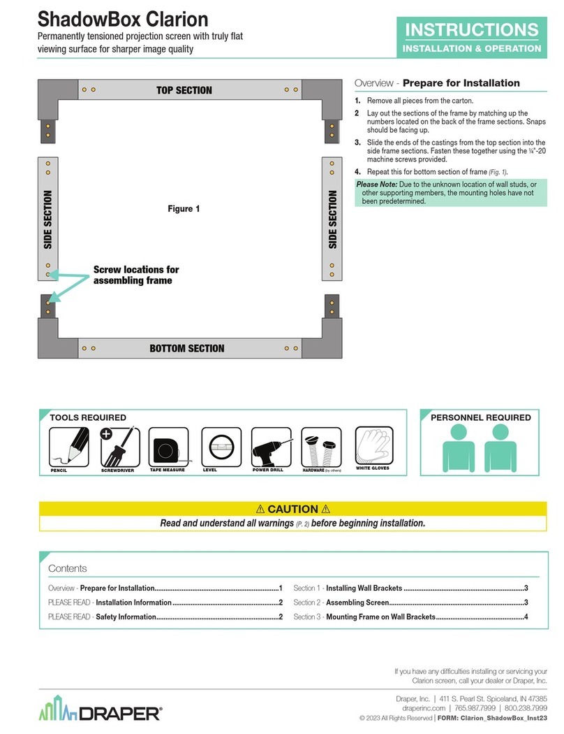
Draper ShadowBox Clarion User manual

Draper

Draper ShadowBox Clarion User manual

Draper AeroLift 150 User manual

Draper

Draper AeroLift 150 User manual

Draper AeroLift 50 User manual

Draper

Draper AeroLift 50 User manual

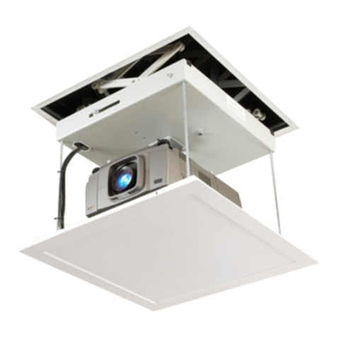
Draper Scissor Lift SL User manual

Draper

Draper Scissor Lift SL User manual

Draper Silhouette/V Guide

Draper

Draper Silhouette/V Guide

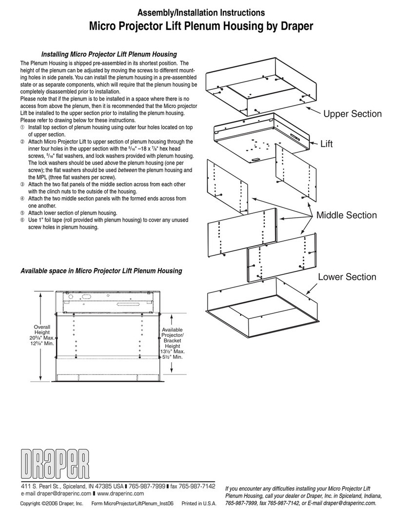
Draper Micro Projector Lift User manual

Draper

Draper Micro Projector Lift User manual

Draper Large Targa User manual

Draper

Draper Large Targa User manual

Draper AeroLift 35 Programming manual

Draper

Draper AeroLift 35 Programming manual

Draper AeroLift 150 Manual

Draper

Draper AeroLift 150 Manual

Draper AeroLift 35 Manual

Draper

Draper AeroLift 35 Manual

Draper Micro Projector Lift Programming manual

Draper

Draper Micro Projector Lift Programming manual

Draper AeroLift 35 User manual

Draper

Draper AeroLift 35 User manual

Popular Projector Accessories manuals by other brands

Celexon HomeCinema Plus operating instructions

Celexon

Celexon HomeCinema Plus operating instructions

Lindy 32700 user manual

Lindy

Lindy 32700 user manual

Huawei TP3106 user guide

Huawei

Huawei TP3106 user guide

TEXONIC PX Series instruction manual

TEXONIC

TEXONIC PX Series instruction manual

Dynamic Projection Mirror Head MH14 manual

Dynamic Projection

Dynamic Projection Mirror Head MH14 manual

Grandview GPCM-J Series instruction manual

Grandview

Grandview GPCM-J Series instruction manual

Navitar 682MCL012 installation instructions

Navitar

Navitar 682MCL012 installation instructions

Sanyo LNS-W32 - Wide-angle Lens - 22.3 mm Replacement procedure

Sanyo

Sanyo LNS-W32 - Wide-angle Lens - 22.3 mm Replacement procedure

SP Controls PT-LB10VU Quick start & reference guide

SP Controls

SP Controls PT-LB10VU Quick start & reference guide

Grandview GPCN-E200 instruction manual

Grandview

Grandview GPCN-E200 instruction manual

CHIEF SL220 Service manual

CHIEF

CHIEF SL220 Service manual

Accessory Power USA GEAR PRO Series user guide

Accessory Power

Accessory Power USA GEAR PRO Series user guide

Monacor IMG STAGELINE PAR-56L/CR operating instructions

Monacor

Monacor IMG STAGELINE PAR-56L/CR operating instructions

Da-Lite 22516 installation instructions

Da-Lite

Da-Lite 22516 installation instructions

Eiki PjNET-10 Installation and operation

Eiki

Eiki PjNET-10 Installation and operation

Elite Screens CineGrey 5D Care and use

Elite Screens

Elite Screens CineGrey 5D Care and use

EluneVision Elara NanoEdge user guide

EluneVision

EluneVision Elara NanoEdge user guide

3M Wireless Network Module EP8790NET Operator's guide

3M

3M Wireless Network Module EP8790NET Operator's guide

manuals.online logo
manuals.online logoBrands
  • About & Mission
  • Contact us
  • Privacy Policy
  • Terms and Conditions

Copyright 2025 Manuals.Online. All Rights Reserved.