Scissor Lift SL by Draper page 2 of 6
.draperinc.com (765) 987-7999
Preferred Method—Adjusting Projector Pan
The Projector Pan can be moved forward or back.
Make sure Bottom Pan is supported.
Remove the Lifting Cable Bar.
Remove screws holding Projector Pan on Bottom Pan.
Move Projector Pan forward or back.
Replace screws.
Replace Lifting Cable Bar.
Secondary Method—Adjusting Lifting Cable Bar
(if above does not work)
Run the unit to its "Service" position and make sure Bottom Pan is level.
Try and set so that bottom pan is not more than ¾" out of level.
However, the pan does not have to be perfectly level, as long as the
positioning is consistent and repeatable in "Show" and "Closed"
positions.
Make sure Bottom Pan is supported.
Remove screws holding Lifting Cable Bar to the Projector Pan.
Move Lifting Cable Bar forward or back.
Replace screws.
Check level again. If still not level, repeat.
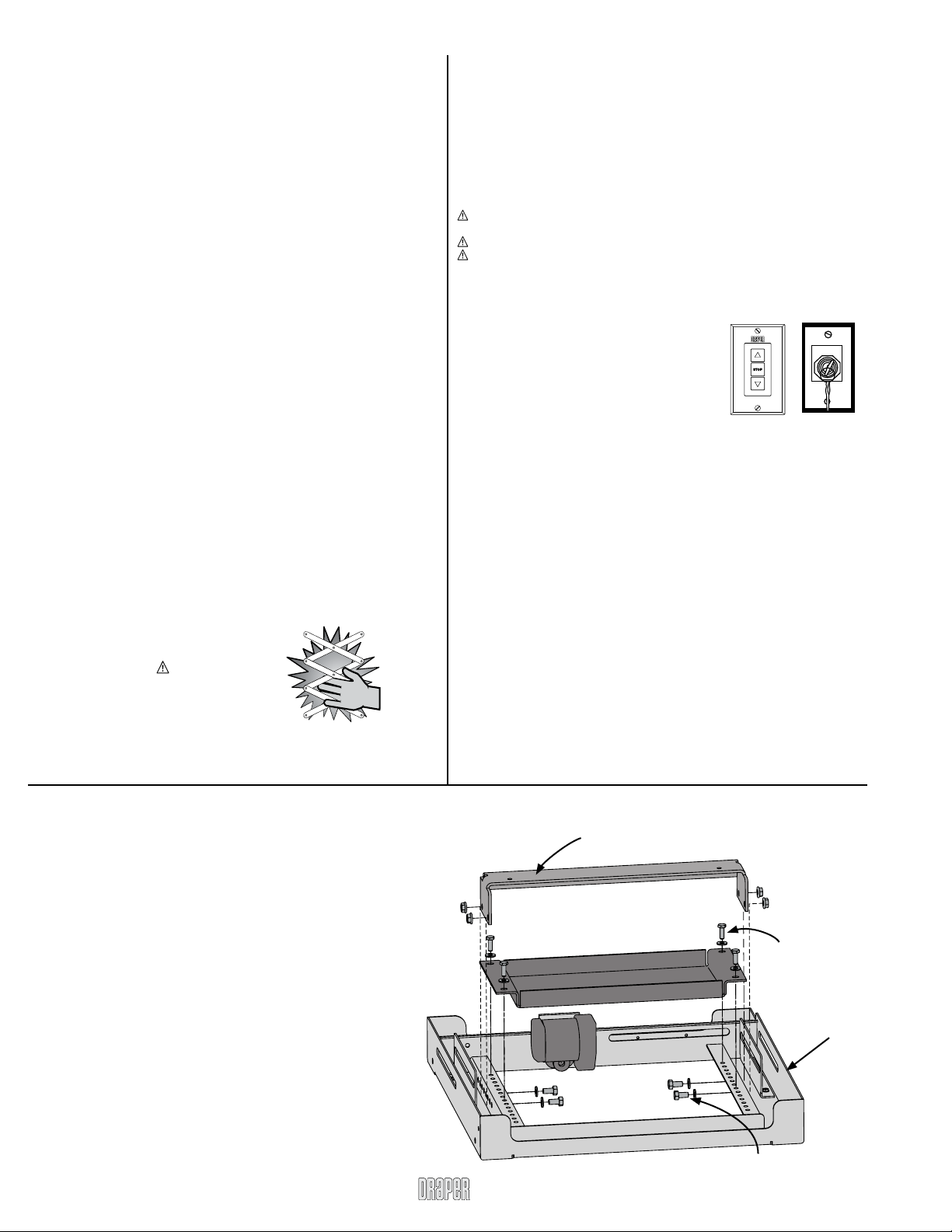
Adjusting for Level or Center of Gravity (See Fig. 2 Below)
Hanging Unit
Please note: If using Environmental Air Space Housing option, see
installation instructions included with Environmental Air Space Housing.
The Scissor Lift may be installed in a variety of ways; recessed above the
ceiling, or suspended below the ceiling. The lift should be supported by four
3
/
8
"
threaded mounting rods or bolts with locking nuts. If ceiling recessed, the entire
unit (including the projector) should set approximately 1½" above the finished
ceiling in its “stored” position. The threaded rods should pass through the corner
mounting flanges and be secured by nuts above and below. The unit should then
be guy wired or blocked to prevent swinging.
All installations should observe the following guidelines:
If installing above a hard ceiling, optional Draper Access Panels are available to
allow access to the unit.
Installer must ensure that all fasteners and supports are of adequate strength to
securely support Scissor Lift and projector.
Fastening methods must be suitable for mounting surface, and securely
anchored so that vibration or abusive pulling on unit will not weaken installation.
Unit should be level, with weight shared more or less equally by all four
threaded mounting rods.
Bottom of unit must be unobstructed after installation. Sufficient clearance must
be allowed below projector or optional ceiling closure.
Unit must be secured independent from suspended ceiling and do not use unit
to support adjacent ceiling, light fixtures, etc.
Unit to be installed so when lowered to its lowest point, it is a minimum of 8 feet
(2.44 m) above the floor.
Do not complete the ceiling below unit until electrical connections have been
completed and unit has been operated successfully.
We recommend that safety cables be attached to the Scissor Lift SL for added
security (a sound installation practice with overhead equipment).
When the Scissor Lift SL is to be installed in “other space used for en-
vironmental air” the optional Environmental Air Space Housing must be
installed per instructions to isolate the lift from the “other space used for
environmental air.”
When Scissor Lift SL is NOT installed in environmental air space housing and
optional ceiling closure, the ALTERNATE wiring for 'UP' limit switch may be
used. Disconnect both BLACK (BK) wires from 'UP' limit switch and quick
connect them together usingthe provided jumper cable (see Alternate Wiring
schematic on page 5).
Figure 2
3
/
8
"-18 x 1" hex head cap
screws for attaching Lifting
Cable Bar to Bottom Pan
¼"-20 x ¾" hex head
cap screws for
attaching Projector
Pan to Bottom Pan
Lifting Cable Bar
Projector Pan
Bottom Pan
Operation
Before operating or testing the unit, make sure the packaging has been
removed from the unit. Remove the corrugated block from the cardboard sleeve
(bottom-most packaging material), then collapse the sleeve and remove it, along
with the rest of the packaging. Next, using the 3 button switched, operate the lift in
the "up" direction, so the lift's control encoder will recognize it's "home" location.
Until you do this, the Down function will not work. You must also do this if the
Scissor Lift ever loses or is disconnected from the power.
When unit is first operated, be cautious! If unit fails to operate properly, press
“STOP” and recheck electrical connections before proceeding. Cycle unit down
and up several times to confirm satisfactory operation.
Caution: Do not pull on or touch safety belt when unit is in motion. If belt
locks, the cables will unspool.
Caution: Obstructing bottom pan may cause cables to unspool.
Caution: Do not operate Scissor Lift SL without a minimum of 15 lbs. of
weight attached to the pan. Operating without weight may cause cables to
unspool.
Standard Single Station Low Voltage Control
(See Fig. 1)—
One three-button switch with “UP”, “DOWN”,
and “STOP” buttons. Lift starts up or down when
appropriate button is pressed, and may be stopped
by pressing “STOP” button. Factory set limit
switches stop lift automatically when projector is in
“show” position. One momentary key switch lowers
lift from “show” to “service” position.
Optional Multiple Station Control—
Optional, moves lift from “stored” to “show” position only. Each switching station has
a three-button switch with “UP”, “DOWN”, and “OFF” buttons. Lift starts up or down
when appropriate button is pressed, and may be stopped by pressing “OFF” button.
Factory set limit switches stop lift automatically when projector is in “show” position.
Optional Key Operated Switch—
If ordered, the standard Lift LV Switch can be replaced with a second single
station, momentary key-operated three position (up/off/down) switch. Multiple
Station Control required for this option. Moves lift from “stored” to “show” position
only.
Optional Infrared or Radio Frequency Remote Control—If ordered, a three-
button transmitter is provided, with “UP”, “DOWN”, and “STOP” buttons. Unit starts
up or down when appropriate button is pressed, and may be stopped by pressing
“OFF” button. Factory set limit switches stop unit automatically when projector is in
“show” position. Only controls "show" and "stored" positions.
Optional RS232 Control—For Serial communication an R2D7 Serial
Communications Interface is optionally available.
Low Voltage Trigger—Input provided for Low Voltage Trigger from projector
(see diagram on page 4).
Please Note:
Scissor Lift SL must be installed in accordance with the requirements of the
Local Building Codes, the Canadian Electrical Code (CEC), CAN/CSA C22.1
and the National Electric Code (NEC), NFPA 70, as required. An appropriate
disconnect device shall be provided as part of the building installation. Scissor Lift SL is approved to UL 2442 and CSA C22.2 No. 60065-03.
2¾"
4½"
7/8"
Front Side Back
D C U
Lift LV Switch
Up & Show
UP
OFF
DOWN
UP DOWN
OFF
SP-KSM
Service
Figure 1
Caution:
Beware of pinch points
Caution: Beware
of pinch points


