CAUTION
Closely monitor the electrical stroke, as the travel limit
switches are not yet properly adjusted. Ensure the
actuator does not over-travel and damage the driven
equipment.
CAUTION
Closely monitor the electrical stroke, as the travel limit
switches are not yet properly adjusted. Ensure the
actuator does not over-travel and damage the driven
equipment.
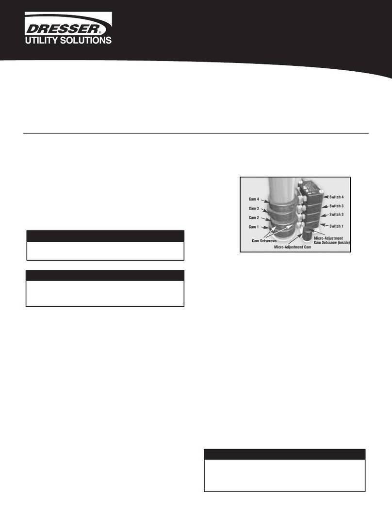
d. Upon reaching the opposite end of travel, Cam
7 should just engage the roller on Switch 7 so that
the switch just “breaks”. This action will stop the
actuator. Check that the actuator has properly
positioned the driven equipment.
e. If actuator travel is insufficient, rotate Cam 7
slightly clockwise until the cam just clears the roller
of Switch 7. As soon as the cam clears the roller, the
actuator will “bump” electrically towards the end of
travel. Continue until the actuator reaches the full
end of travel.
f. If the actuator has over-traveled, rotate Cam 7
slightly counter-clockwise, then move the actuator
towards the fail position electrically. Stop and
electrically reverse the direction of travel. Move the
actuator until Cam 7 operates Switch 7 and the
actuator stops. Repeat this procedure until the
actuator is properly positioned. Tighten the
setscrews on Cam 7.
Switch adjustments for counter-clockwise spring fail
operation (viewed from the top of the actuator)
a. Ensure the actuator is de-energized and postioned
in the counter-clockwise (fail) position. Ensure the
end of travel stop is properly adjusted. Rotate the
screw counter-clockwise to move the actuator
output shaft in a counter-clockwise direction.
Rotate the screw in a clockwise direction
to move the actuator output shaft in a clockwise
direction. Loosen the setscrews on Cam 7. Rotate
clockwise until it clears the switch arm roller
of switch 7.
b. Rotate Cam 7 counter-clockwise until it comes in
contact with Switch 7’s roller arm and the switch
“breaks”. A light “click” can be heard. Tighten the
setscrews on Cam 7.
c. Energize the actuator. This will move the actuator
to the opposite end of travel.
d. Upon reaching the opposite end of travel, Cam 2
should just engage the roller on Switch 2 so that
the switch just “breaks”. This action will stop the
actuator. Check that the actuator has properly
positioned the driven equipment.
e. If actuator travel is insufficient, rotate Cam 2
slightly counter-clockwise until the cam just clears
the roller of Switch 2. As soon as the cam clears the
roller, the actuator will “bump” electrically towards
the end of travel. Continue until the actuator
reaches the full end of travel.
f. If the actuator has over-traveled, rotate Cam 2
slightly clockwise, then move the actuator towards
the fail position electrically. Stop and electrically
reverse the direction of travel. Move the actuator
until Cam 2 operates switch 2 and the actuator
stops. Repeat this procedure until the actuator is
properly positioned. Tighten the setscrews
on Cam 2.
6. Operate the actuator electrically several times to ensure
proper operation and to verify that travel limits and stops
are correctly set.
7. De-energize the actuator to verify proper spring failure
operation. Ensure the driven device is properly positioned
in the spring failure position.
8. If the actuator is supplied with an optional feedback
potentiometer and/or position controller, verify proper
calibration of input and output signals after making cam
and stop bolt adjustments.
9. Replace the actuator cover and cover screws.
10. The actuator is now ready for electrical operation.
