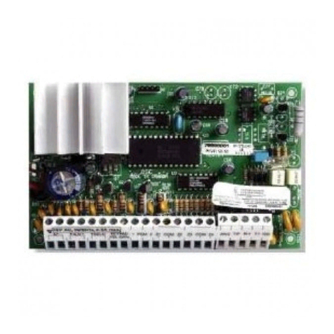
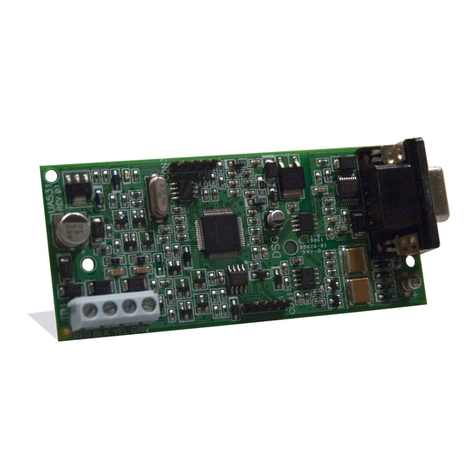
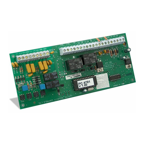
DSC ESCORT558OTC User manual

ESCORT558OTC
Version 2.1
• W A R N I N G •
This manual contains information on limitations regarding product use and function and
information on the limitations as to liability of the manufacturer.
Installation
Manual

WARNING Please Read Carefully
System Failures
This system has been carefully designed to be as effective as possible. There
are circumstances, however, involving fire, burglary, or other types of emer-
gencies where it may not provide protection. Any alarm system of any type
may be compromised deliberately or may fail to operate as expected for a
variety of reasons. Some but not all of these reasons may be:
nn
nn
n Inadequate Installation
A security system must be installed properly in order to provide adequate pro-
tection. Every installation should be evaluated by a security professional to
ensure that all access points and areas are covered. Locks and latches on win-
dows and doors must be secure and operate as intended. Windows, doors,
walls, ceilings and other building materials must be of sufficient strength and
construction to provide the level of protection expected. A reevaluation must
be done during and after any construction activity. An evaluation by the fire
and/or police department is highly recommended if this service is available.
nn
nn
n Criminal Knowledge
This system contains security features which were known to be effective at the
time of manufacture. It is possible for persons with criminal intent to develop
techniques which reduce the effectiveness of these features. It is important that
a security system be reviewed periodically to ensure that its features remain
effective and that it be updated or replaced if it is found that it does not provide
the protection expected.
nn
nn
n Access by Intruders
Intruders may enter through an unprotected access point, circumvent a
sensing device, evade detection by moving through an area of insufficient
coverage, disconnect a warning device, or interfere with or prevent the
proper operation of the system.
nn
nn
n Power Failure
Control units, intrusion detectors, smoke detectors and many other security
devices require an adequate power supply for proper operation. If a device
operates from batteries, it is possible for the batteries to fail. Even if the batter-
ies have not failed, they must be charged, in good condition and installed cor-
rectly. If a device operates only by AC power, any interruption, however brief,
will render that device inoperative while it does not have power. Power inter-
ruptions of any length are often accompanied by voltage fluctuations which
may damage electronic equipment such as a security system. After a power
interruption has occurred, immediately conduct a complete system test to en-
sure that the system operates as intended.
nn
nn
n Failure of Replaceable Batteries
This system’s wireless transmitters have been designed to provide several years
of battery life under normal conditions. The expected battery life is a function
of the device environment, usage and type. Ambient conditions such as high
humidity, high or low temperatures, or large temperature fluctuations may re-
duce the expected battery life. While each transmitting device has a low bat-
tery monitor which identifies when the batteries need to be replaced, this monitor
may fail to operate as expected. Regular testing and maintenance will keep the
system in good operating condition.
nn
nn
n Compromise of Radio Frequency (Wireless)
Devices
Signals may not reach the receiver under all circumstances which could
include metal objects placed on or near the radio path or deliberate jam-
ming or other inadvertent radio signal interference.
nn
nn
n System Users
A user may not be able to operate a panic or emergency switch possibly due to
permanent or temporary physical disability, inability to reach the device in
time, or unfamiliarity with the correct operation. It is important that all system
users be trained in the correct operation of the alarm system and that they
know how to respond when the system indicates an alarm.
nn
nn
n Smoke Detectors
Smoke detectors that are a part of this system may not properly alert occupants of
a fire for a number of reasons, some of which follow. The smoke detectors may
have been improperly installed or positioned. Smoke may not be able to reach the
smoke detectors, such as when the fire is in a chimney, walls or roofs, or on the
other side of closed doors. Smoke detectors may not detect smoke from fires
on another level of the residence or building.
Every fire is different in the amount of smoke produced and the rate of
burning.Smokedetectorscannotsensealltypesoffiresequallywell.Smoke
detectors may not provide timely warning of fires caused by carelessness
or safety hazards such as smoking in bed, violent explosions, escaping
gas, improper storage of flammable materials, overloaded electrical cir-
cuits, children playing with matches or arson.
Even if the smoke detector operates as intended, there may be circumstances
when there is insufficient warning to allow all occupants to escape in time to
avoid injury or death.
nn
nn
n Motion Detectors
Motion detectors can only detect motion within the designated areas as
shown in their respective installation instructions. They cannot discrimi-
nate between intruders and intended occupants. Motion detectors do not
provide volumetric area protection. They have multiple beams of detec-
tion and motion can only be detected in unobstructed areas covered by
these beams. They cannot detect motion which occurs behind walls, ceil-
ings, floor, closed doors, glass partitions, glass doors or windows. Any
type of tampering whether intentional or unintentional such as masking,
painting, or spraying of any material on the lenses, mirrors, windows or
any other part of the detection system will impair its proper operation.
Passive infrared motion detectors operate by sensing changes in tempera-
ture. However their effectiveness can be reduced when the ambient tem-
perature rises near or above body temperature or if there are intentional or
unintentional sources of heat in or near the detection area. Some of these
heat sources could be heaters, radiators, stoves, barbeques, fireplaces,
sunlight, steam vents, lighting and so on.
nn
nn
n Warning Devices
Warning devices such as sirens, bells, horns, or strobes may not warn
people or waken someone sleeping if there is an intervening wall or
door. If warning devices are located on a different level of the residence
or premise, then it is less likely that the occupants will be alerted or
awakened. Audible warning devices may be interfered with by other
noise sources such as stereos, radios, televisions, air conditioners or
other appliances, or passing traffic. Audible warning devices, however
loud, may not be heard by a hearing-impaired person.
nn
nn
n Telephone Lines
Iftelephonelinesareused totransmitalarms, theymaybe outofservice orbusy
forcertain periods oftime.Also anintrudermay cut thetelephoneline ordefeat
its operation by more sophisticated means which may be difficult to detect.
nn
nn
n Insufficient Time
Theremaybe circumstances when the systemwilloperate as intended, yet the
occupants will not be protected from the emergency due to their inability to
respond to the warnings in a timely manner. If the system is monitored, the
response may not occur in time to protect the occupants or their belongings.
nn
nn
n Component Failure
Althoughevery efforthas beenmadeto makethissystem asreliableas possible,
the system may fail to function as intended due to the failure of a component.
nn
nn
n Inadequate Testing
Most problems that would prevent an alarm system from operating as in-
tended can be found by regular testing and maintenance. The complete
system should be tested weekly and immediately after a break-in, an at-
tempted break-in, a fire, a storm, an earthquake, an accident, or any kind
of construction activity inside or outside the premises. The testing should
include all sensing devices, keypads, consoles, alarm indicating devices
and any other operational devices that are part of the system.
nn
nn
n Security and Insurance
Regardless of its capabilities, an alarm system is not a substitute for
property or life insurance. An alarm system also is not a substitute for
property owners, renters, or other occupants to act prudently to prevent
or minimize the harmful effects of an emergency situation.
1
ESCORT5580TC
Thank you
for purchasing the DSC Escort5580TC module. When connected to the main control panel,
themoduleturnsanytouchtonetelephone–localorremote–intoafullyfunctionalkeypad.Onceactivated,
theEscort5580TCwillactasaguidefortheuser.TheEscort5580TCwillprompttheuserthroughclear,easy
to understand sentences, telling them what the next key entry should be to perform the various functions
available.
I
n addition to a library of over 250 system words, a powerful “say number” command is available on the
Escort5580TC. This feature allows any number between zero and 999 to be said in three different ways.
Up to six words can be used for Zone Labels, Automation Items, Automation Modes and System Labels,
thereby enhancing the Escort5580TC’s versatility.
T
he Escort5580TC has built-in temperature control for standard forced air and heat pump systems. The
Escort can control up to four thermostats. Each thermostat has four programmable temperature ranges
called occupancy settings. Each occupancy setting can be turned on by the user, or by the Escort with
schedules, panel events and/or modes.
T
he module also has a built-in line carrier interface. This feature allows the module to control up to 32 line
carrier automation type items for lighting control, other home automation features. Automation items can
be can be turned on by the user, or by the Escort with schedules, panel events and/or modes. A full range
of dimming levels are also available for lighting control.
W
e are confident that you and your customer will discover that the Escort5580TC module is the most
useful alarm control panel enhancement product available on the market today.
W
e welcome your input. Please send your comments to:
Digital Security Controls
c/o Escort5580TC Product Manager
3301 Langstaff Road
Concord, ON
Canada L4K-4L2

2
N O T E S

3
Table of Contents
System Introduction................................................................................................................................... 5
1.1 Specifications ........................................................................................................................................ 5
1.2 About this Manual.................................................................................................................................. 5
Getting Started............................................................................................................................................6
2.1 Installation Steps ................................................................................................................................... 6
2.2 Keybus Wiring ....................................................................................................................................... 6
2.3 Telephone Line Wiring ........................................................................................................................... 7
2.4 Enrolling the Escort5580TC Module...................................................................................................... 7
2.5 Connecting the PL-513 or PSC04 Controller......................................................................................... 7
2.6 Connecting the EMS Thermostat and Additional Sensors .................................................................... 8
How to Program ..........................................................................................................................................9
3.1 Entering Installer Programming ............................................................................................................. 9
3.2 Programming Data Entry Sections ........................................................................................................9
3.3 Programming Toggle Option Sections .................................................................................................. 9
3.4 Programming Label Entry Sections..................................................................................................... 10
3.5 Reviewing Programming ..................................................................................................................... 10
3.6 Exiting Programming ........................................................................................................................... 10
Escort5580TC Access Programming ..................................................................................................... 11
4.1 Accessing the Escort5580TC Locally ................................................................................................. 11
4.2 Accessing the Escort5580TC Remotely..............................................................................................11
4.3 Global or Partition Operation............................................................................................................... 11
4.4 Receiving Incoming Calls.................................................................................................................... 12
4.5 Programming Audio (User) Help ......................................................................................................... 12
General Escort5580TC Programming ....................................................................................................13
5.1 Programming Escort5580TC Prompts.................................................................................................13
5.2 Changing the Telephone Access Code .............................................................................................. 13
5.3 Changing Local Programming Lockout ..............................................................................................13
5.4 Programming the Clock.......................................................................................................................13
Automation Item Programming............................................................................................................... 14
6.1 Enabling Home Automation.................................................................................................................14
6.2 Programming Automation Item Operation...........................................................................................14
6.3 Programming How Automation Items are Activated ........................................................................... 15
6.4 Programming the House Code & Unit Number ................................................................................... 16
6.5 Programming Automation Item Options ..............................................................................................16
6.6 Assigning Automation Items to Schedules .........................................................................................17
6.7 Assigning Automation Items to Modes................................................................................................ 17
6.8 Assigning Automation Items to PGM Outputs .....................................................................................18
6.9 Programming Automation Items to Follow Zones................................................................................ 18
Automation Schedule Programming ......................................................................................................19
7.1 Programming Schedules ..................................................................................................................... 19

4
Mode Programming .................................................................................................................................. 20
8.1 Automation Items and Modes .............................................................................................................20
8.2 Thermostat Occupancy Settings and Modes ..................................................................................... 20
8.3 Programming Modes to Follow PGM Outputs ..................................................................................... 21
Temperature Control Programming .......................................................................................................22
9.1 How Temperature Control Works......................................................................................................... 22
9.2 Programming Temperature Control Operation ....................................................................................23
9.3 Selecting an Address for a Thermostat...............................................................................................23
9.4 Programming How Occupancy Settings Are Turned On .................................................................... 23
9.5 Selecting Thermostat Options .............................................................................................................24
9.6 Assigning Schedules for Temperature Control....................................................................................25
9.7 Assigning Occupancy Settings to Modes........................................................................................... 25
9.8 Assigning Occupancy Settings to PGM Outputs ................................................................................ 26
Programming Worksheets .......................................................................................................................27
System Programming ................................................................................................................................. 27
Telephone Access Programming ............................................................................................................... 29
Schedule Programming .............................................................................................................................. 30
Automation Items ........................................................................................................................................ 31
Automation Item Zone Follower Assignments ............................................................................................37
Assigning Modes to Follow PGM Outputs..................................................................................................40
Automation Item Pulse Timers .................................................................................................................... 41
Automation Item Output Follower ............................................................................................................... 42
Label Programming .................................................................................................................................... 43
Thermostat Control Programming............................................................................................................... 46
Thermostat Labels ...................................................................................................................................... 49
Special Programming ................................................................................................................................. 49
Appendix A: Escort5580TC Label Library ............................................................................................. 50
Appendix B: Automation Item House Codes & Unit Number..............................................................51
Appendix C: [*][5] Menu Commands ......................................................................................................52
Appendix D: [*][6] Options ......................................................................................................................53
Appendix E: Access Code Programming .............................................................................................. 54
Appendix F: Glossary ..............................................................................................................................55
T A B L E O F C O N T E N T S

5
1.1 Specifications
Escort5580TC Module
• Current draw: 130mA - operating, 65 mA -
standby
• Voltage 12VDC
Voice Prompting
• Allprompts are incomplete sentences using a
pleasant, easy to understand female voice
• Panel status is constantly announced, when
applicable, including bypass, trouble, alarm
memory and zone status.
Library
• 250+ system words
• 240+ words for programming labels
• Powerful‘saynumber’commandcanannounce
anynumberfrom0through999inthreedifferent
ways
Programmable Labels
• System Zone Labels
• Automation Item Labels
• Mode Labels
• Miscellaneous System Labels
• System Partition Labels
• Thermostat Labels
Automation Control
• RequirestheconnectionofthePL-513orPSC04
X-10 controller module
• Control up to 32 line carrier X-10 Automation
Items
• A full range of dimming levels for lighting
control
• Global ON/OFF command
Temperature Control
• Availablewiththefollowingcontrolpanelsonly:
PC5010 v2.x, PC5015 v2.x, PC5008 v2.x.
• Requires the connection of at least one EMS
thermostat
• Connect and control up to four thermostats
• Each thermostat has four sets of temperature
ranges: Day Occupancy Setting, Night
Occupancy Setting, Auxiliary Occupancy
Setting, Away Occupancy Setting.
• UptosixEMS-ITSmodules(indoortemperature
sensors) can be connected to each EMS
thermostat for temperature averaging
• One EMS-OTS module (outdoor sensor) can
beconnectedtoeachEMSthermostattodetect
and report the outdoor temperature
Additional Features
• Manual control of Automation Items and
temperature
• 16scheduleswithONTime,OFFTimeandDay
of Week Mask
• 8 user-controlled modes
• Event-activated control of Automation Items
and temperature for any PGM Output option
supported by the main control panel
Downloading
• All Escort5580TC programming can be done
via DLS-1 v6.5 or higher software
1.2 About this Manual
In this manual, Escort voice messages are printed
inboldandareenclosedinquotes, asshownhere:
“Enter y“Enter y
“Enter y“Enter y
“Enter your access code”our access code”
our access code”our access code”
our access code”
YoucanprogramlabelsfortheEscorttoannounce
whenitreferstothingssuchaszonesandpartitions
(e.g. "East wing" instead of "Partition 2"). Some
sections give examples of programmed labels.
These examples are enclosed in brace brackets,
as shown here:
“Program the Escort5580TC to announce
an appropriate label, such as {Holiday
Mode} for mode 01. “
Wheninstructedtopressakeyorkeys,symbolsfor
the keys will be enclosed in square brackets, as
shown here: Enter [✱]
S E C T I O N 1
System Introduction

6
Follow these steps to install the Escort5580TC.
Review the installation and programming sections
of this manual before you begin.
2.1 Installation Steps
Step 1: Mount the Escort5580TC Module
MounttheEscort5580TCmoduleinthesamecabinet
as the main control panel using the nylon standoffs
provided. You can mount the module in a separate
cabinet, but it must be located close to the control
panel in order to hook up the telephone line.
Step 2: Connect the Keybus
(Section 2.2)
Connectthe4wireKeybusaccordingtothediagram
in
Section 2.2 “Keybus Wiring”.
Step 3: Telephone Line Connection
(Section 2.3)
Connect the incoming telephone line according to
thediagramin
Section2.3“TelephoneLineWiring”.
Step 4: Enroll the Escort5580TC Module
(Section 2.4)
Enroll the Escort5580TC module according to the
guideline provided in
Section 2.4 “Enrolling the
Escort5580TC Module”
.
Step 5: Connect the PL-513 or PSC04
Controller
(Section 2.5)
Ifyouwillbeaddingautomationitemstothesystem,
connectthePL-513orPSC04Controlleraccording
to the diagram in
Section 2.5 “Connecting the PL-
513 or PSC04 Controller”.
Step 6: Connect the EMS Thermostat and
Temperature Sensors
(Section 2.6)
If you will be adding temperature control to the
system, connect one or more thermostats to the
Escort5580TC according to Figure 3
.
Refer to
Figure 4, if you will be connecting additional
temperature sensors.
Temperature control will only work on
control panels that:
• support Escort5580 modules
• have software version 2.x or higher.
Step 7: Program the Escort5580TC
You can program the Escort5580TC via any local
touchtone telephone. Follow the guidelines in
Section4“HowtoProgram”
.Youcanalsoprogram
the Escort5580TC using DLS-1 v6.5 or higher
downloading software. Refer to the DLS-1 manual
for more information.
Step 8: Test the System
TesttheEscort5580TCusingbothlocalandremote
telephones. Check all programmed labels and the
operation of all functions including automation
items, if connected.
Remote Access will be disabled on all
UL listed systems.
2.2 Keybus Wiring
TheEscort5580TCmodulehas4terminalsmarked
Keybus (red, black, yellow and green). Connect
these terminals to the 4 terminals on the main
control panel marked Keybus (red, black, yellow
and green).
Figure 1: Keybus Connection
S E C T I O N 2
Getting Started

7
2.3 Telephone Line Wiring
The Escort5580TC module has 4 terminals for the
telephone line connection (TIP, RING, T1 and R1).
The wiring must be as follows:
• Main Control Panel TIP and RING - incoming
line
• Main Control Panel T1 and R1 - Escort5580TC
TIP and RING
• Escort5580TC T1 and R1 - house phones
4. To confirm supervision, re-enter Installer
Programmingandthenentersection[903].On
LED keypads, light 24 ON represents
successfulEscort5580TCsupervision.OnLCD
keypads, the description “Escort5580” will be
displayed if successful.
5. If this is not successful, check all wiring to the
Escort5580TC.
2.5 Connecting the PL-513 or
PSC04 Controller
TheRJ-11XtelephonejackontheEscort5580TCis
for connecting the PL-513 or PSC04 Controller.
Use an RJ-11X connector cable to connect the
Escort5580TC to the PL-513 or PSC04. Plug the
PL-513 or PSC04 Controller module into any
unswitched AC outlet. Connect automation items
for lighting, outlet and temperature control. These
items plug into AC outlets located throughout the
installation.
The PL-513 or PSC04 Controller receives
commands from the Escort5580TC module and
sendsoutsignalstocontrolthevariousautomation
items connected.
The following diagram shows the cable currently
required for connecting the Escort5580TC to the
PL-513or PSC04.With thejacks sideby side(tabs
facing up), the colours of the wire in each jack will
appear in the same order from left to right. This
cable is called a “Straight Through Cable” as per
telephone industry standards.
Please do not use a “Swapped”,
“Flipped” or “Crossover” cable as it
will not work with the Escort5580TC.To
verify whether you have the correct
type of cable, plug in the PSC04
(PL513).The red LED should turn ON.
Connect the telephone cable to both
the PSC04 (PL513) and the
Escort5580TC If the LED on the PSC04
(PL513) turns OFF and remains unlit,
you are using the wrong type of cable.
G E T T I N G S T A R T E D
Figure 2: Telephone Connection
2.4 Enrolling the Escort5580TC
Module
The Escort5580TC will function properly as soon as
allwiringiscompleteandpowerisapplied.However,
to fully supervise the Escort5580TC from PC5010
v1.x control panels, you needto followthese steps:
Procedure on the PC50XX v1.x
1. Wire the Escort5580TC module to the Keybus
and telephone line.
2. At a keypad, enter [✱][8][Installer’s Code] to
enter Installer Programming.
3. Enter section [902], then press [#] to exit
Installer Programming. The panel will
automatically search for all modules on the
system. The search takes approximately 1
minute. From this point on, if any modules are
removed from the system, a Supervisory
Trouble will be generated.

8
2.6 Connecting the EMS
Thermostat and Additional
Sensors
When connected to the Escort5580TC, an EMS
Thermostat allows users to detect and control the
indoor temperature of the premises locally or
remotely from any touchtone telephone. The
Escort5580TC can announce either temperature
(exterior temperature only if an EMS-OTS module
isattached and enabled).The LCD5500Zcan also
display the temperature(s) and allows the user to
access temperature controls.
Figure 3 illustrates how the EMS thermostat
connects to the Escort5580TC. Refer to the
EMS
Thermostat Installation Sheet
for more details.
Figure 3: Connecting the Escort5580TC to an EMS
thermostat.
Connecting Indoor Sensors (EMS-ITS)
The thermostat has its own temperature sensor
built in. You can install additional indoor sensors
for more accurate temperature control. Use
EMS-ITS sensors to measure temperature at a
remote location from the thermostat (where the
thermostat’s own sensor is disabled), or for
temperature averaging in large rooms or between
different rooms.
Connecting an indoor temperature
sensor (EMS-ITS) disables the thermo-
stat temperature sensor.
Upto6EMS-ITSsensorsmaybeinstalled.Connect
thesensors to the thermostat as shown in Figure 4.
Figure 4: Connecting thermostat to additional
sensors.
The maximum distance sensors may be installed
from the thermostat is 90 m (300’). Refer to the
EMS-ITS Installation Sheet
for more details.
Connecting the EMS-OTS (Outdoor Sensor)
The EMS-OTS senses outdoor air temperature via
an exterior wired probe. This temperature can be
displayed on the thermostat but does not affect
thermostat function.
Only one EMS-OTS module may be installed per
thermostat.ConnecttheEMS-OTStothethermostat
inseriesthesamewayas an EMS-ITS module(see
Figure 4). Insert the EMS-OTS at any point in a
chain with other sensors. Refer to the
EMS-OTS
Installation Sheet
for more details.
G E T T I N G S T A R T E D

9
The following sections describe how to program
theEscort5580TC.AllEscort5580TCprogramming
can be done via any local touchtone telephone or
via the DLS software.
It is extremely important that you read
this section of the manual completely
before attempting to program the
Escort5580TC module.
3.1 Entering Installer
Programming
With the system disarmed:
1. Pickup a local telephone handset.You willhear:
Dial TDial T
Dial TDial T
Dial Tone.one.
one.one.
one.
2. Enterthe TelephoneAccess code. The default
Telephone Access code is [***]. (You can
reprogram this code in section [020].) The
system prompts:“Hello”“Hello”
“Hello”“Hello”
“Hello”
3. Enter programming mode by pressing [✱][8].
The system prompts:
“Enter the Service Code”“Enter the Service Code”
“Enter the Service Code”
4. Enterthe4-digitServicecode.Thedefaultservice
code is [5580]. (You can change the service
code in programming section [001].) After the
service code is entered, the system prompts:
“Enter a Section Number. T“Enter a Section Number. T
“Enter a Section Number. To exit, presso exit, press
o exit, presso exit, press
o exit, press
[#]”[#]”
[#]”[#]”
[#]”
5. Toenteraprogrammingsection,enterthe3-digit
number of the section. If you make an error
enteringthesectionnumber,thesystemprompts:
“Inv“Inv
“Inv“Inv
“Invalid entryalid entry
alid entryalid entry
alid entry. Enter a Section Number.. Enter a Section Number.
. Enter a Section Number.. Enter a Section Number.
. Enter a Section Number.
TT
TT
To exit, press [#]”o exit, press [#]”
o exit, press [#]”o exit, press [#]”
o exit, press [#]”
When you enter a section number, the system
announces the section you have entered with
the prompt:
“Section (number)”“Section (number)”
“Section (number)”
3.2 Programming Data Entry
Sections
ToprogramadataentrysectionfromtheEscort5580
programming mode:
1. Enter the 3-digit section number.
2. The system announces the section you have
entered with the prompt:
“Section (number)”“Section (number)”
“Section (number)”
The system announces the data presently
programmed in the programming section as:
“Data is (data)”“Data is (data)”
“Data is (data)”
The system then prompts:
“Enter ne“Enter ne
“Enter ne“Enter ne
“Enter new data”w data”
w data”w data”
w data”
3. Enter the new data in the section, or return to
the “Enter a Section Number” prompt, by
pressing [#].
Whenyouhavefinishedenteringthenewdata,
the system announces the new data with the
prompt: “Data is (data)”“Data is (data)”
“Data is (data)”“Data is (data)”
“Data is (data)”
If you make an invalid data entry, the system
announces:
“Inv“Inv
“Inv“Inv
“Invalid Entryalid Entry
alid Entryalid Entry
alid Entry. Data is (data). Enter. Data is (data). Enter
. Data is (data). Enter. Data is (data). Enter
. Data is (data). Enter
nene
nene
new data. Tw data. T
w data. Tw data. T
w data. To exit, press pound.”o exit, press pound.”
o exit, press pound.”o exit, press pound.”
o exit, press pound.”
4. Recordthenewdataintheappropriatesection
of the Programming Worksheets.
3.3 Programming Toggle Option
Sections
To program a section with toggle options from the
Escort5580 programming mode:
1. Enter the 3-digit section number.
2. The system announces the section you have
entered with the prompt:
“Section (number)”“Section (number)”
“Section (number)”
Thesystemannounceswhichoptionsarepresently
turned ON with one of the following prompts:
““
““
“All options are ofAll options are of
All options are ofAll options are of
All options are off”f”
f”f”
f”
“All options are on”“All options are on”
“All options are on”
“Option (number) is on”“Option (number) is on”
“Option (number) is on”
“Options (numbers) are on”“Options (numbers) are on”
“Options (numbers) are on”
The system then prompts:
“Enter tw“Enter tw
“Enter tw“Enter tw
“Enter two digit option. To digit option. T
o digit option. To digit option. T
o digit option. To Exit, presso Exit, press
o Exit, presso Exit, press
o Exit, press
pound”pound”
pound”pound”
pound”
3. Toexitthesectionwithoutmakinganychanges,
press [#].
S E C T I O N 3
How to Program

10
To turn an option ON or OFF, enter the 2-digit
option number.
If you enter an invalid option number, the
system prompts:
“Inv“Inv
“Inv“Inv
“Invalid entry”alid entry”
alid entry”alid entry”
alid entry”
Afteryouenteravalidoptionnumber,thesystem
again announces which options are ON.
4. When you have finished programming the
options in the section, press [#]. The system
returnstothe“EnteraSectionNumber”prompt.
5. Record your new programming choices in the
appropriate section of the Programming
Worksheets.
3.4 Programming Label Entry
Sections
To program or change a label:
1. Enter the section number of the label. The
system announces the section number and
then recites the words presently programmed
in the label. Each label may have up to six
words. The system then prompts:
“Enter three digit w“Enter three digit w
“Enter three digit word. Tord. T
ord. Tord. T
ord. To exit, presso exit, press
o exit, presso exit, press
o exit, press
pound”.pound”.
pound”.pound”.
pound”.
2. Enterthefirstwordofthelabelusingthe3-digit
codes from the Label Library in Appendix B of
the Programming Worksheets.
The system beeps at the end of each correctly
entered code and the system prompts:
“Enter three digit w“Enter three digit w
“Enter three digit word. Tord. T
ord. Tord. T
ord. To exit presso exit press
o exit presso exit press
o exit press
pound”pound”
pound”pound”
pound”
If you make an invalid entry, the system
prompts:
“Inv“Inv
“Inv“Inv
“Invalid entryalid entry
alid entryalid entry
alid entry. Enter three digit w. Enter three digit w
. Enter three digit w. Enter three digit w
. Enter three digit word. Tord. T
ord. Tord. T
ord. Too
oo
o
exit press pound”exit press pound”
exit press pound”
3. If you have more words to program, enter the
3-digitcodeofeachworduntilyouarefinished.
4. When you have entered six words, the system
will recite the label. If your label is less than six
words, press [#].
5. To have the system read the new label to you,
entertheprogrammingsectionforthelabelagain.
6. If the label is correct, press [#]. To change the
label again, repeat steps 1-5, above.
7. Recordthenewlabelintheappropriatesection
of the Programming Worksheets.
Adding Numbers to Labels
Threespecial Number Commands are available to
allow the system to include a number in the voice
label. The number commands allow the system to
announce the number in three different modes:
Label 000: Number Command 1, Combined
Form. The number will be announced in its full
form. For example, the number 401 would be
announced as
“four hundred and one”
.
Label 001: Number Command 2, Ordered Form.
The number will be announced in a descriptive
form. For example, the number 401 would be
announced as
“four hundred and first”
.
Label 002: Number Command 3, Individual
Numbers. Each digit in the number will be
announced individually. For example, the number
401 would be announced as
“four zero one”
.
The number commands take up two of the six
available word spaces in a label. In the first space
select the type of announcement for the number
(NumberCommand000,001or002).Inthesecond
spaceprogramthe3-digitnumbertoberead(from
000 to 999).
Because number commands take up 2
label spaces, you cannot program them
in the sixth entry spot for a label.
○○○○○○○○○○○○○○○○○○○○○○○○○
Automation Item Labels ..Sections [451] - [482]
Mode Labels....................Sections [521] - [528]
Command Output Labels Sections [545] - [548]
Partition Labels ...............Sections [561] - [562]
Zone Labels.....................Sections [601] - [633]
○○○○○○○○○○○○○○○○○○○○○○○○○
Thermostat Labels ..........Sections [884] - [887]
3.5 Reviewing Programming
To review the current programming for a section
enterthe3-digitsectionnumber.TheEscort5580TC
will announce the data programmed. If the
programmingiscorrectpress[#]toexitthesection,
otherwise enter the correct data.
3.6 Exiting Programming
When the Escort5580TC announces “Enter
Section Number”, press the [#] key.
P R O G R A M M I N G

11
4.1 Accessing the Escort5580TC
Locally
To access the Escort5580TC locally, pick up any
localtouchtone telephoneand enterthe threedigit
Telephone Access Code (default [
***
]). The
Escort5580TC will seize the line and announce
“Hello.”
If the Access Code Required for Local Access
option is enabled (section [021], option [02]) the
Escort5580TC will announce
“Enter your Access Code.”
InvalidaccesscodescounttowardstheMainPanel
Keypad Lockout, if enabled
(see your system’s
Installation Manual).
TheEscort5580TCwillfunctionevenifthetelephone
line is disconnected. The panel monitors the
telephonelineandifit senses aninterruptiontothe
external telephone line connection it will tell the
Escort5580TC to provide the current required so
that the Escort5580TC will continue to function
locally. For this to operate properly, enable
Telephone Line Supervision on the control panel
(see your system’s Installation Manual).
For UL Listed installations, Local
Access Only (section [021]) must be
enabled.
4.2 Accessing the Escort5580TC
Remotely
Remote Access will be disabled on all
UL listed systems.
Downloading Answer Enabled must be
ON in Section [401] of the PC50XX OR
section [71] of the PC1575/PC1580 for
Remote Access.
IftheRemoteAccessoption(section[021],option
[01]) is enabled the Escort5580TC users can
access the system from any touchtone telephone
in the world.
1. Call the telephone number the Escort5580TC
is connected to.
2. Let the telephone ring one or two times.
3. Hang up and wait 10 seconds before calling
again. The Escort5580TC will answer after the
first or second ring and announce
“Hello.”“Hello.”
“Hello.”“Hello.”
“Hello.”
4. Enter the 3-digit Telephone Access Code. If
this is not entered within 10 seconds the
Escort5580TC will announce
“Goodb“Goodb
“Goodb“Goodb
“Goodbyy
yy
ye,”e,”
e,”e,”
e,”
and hang up. Once the correct code has been
entered, the system will prompt,
“Enter y“Enter y
“Enter y“Enter y
“Enter your Aour A
our Aour A
our Access Code.”ccess Code.”
ccess Code.”ccess Code.”
ccess Code.”
5. Enter a 4- or 6-digit access code. The
Escort5580TCwillbegintoannouncethestatus
of the system. If you do not enter an access
code within 20 seconds, or if you enter it
incorrectly 3 times, the Escort5580TC will
announce “Goodb“Goodb
“Goodb“Goodb
“Goodbyy
yy
ye,”e,”
e,”e,”
e,”
and hang up. Invalid access codes count
towards the Main Panel Keypad Lockout, if
enabled
(see your system’s Installation
Manual).
4.3 Global or Partition Operation
IfyouareconnectingtheEscort5580TCtoasystem
with 2 partitions, you can program the Escort to
allow access to both partitions (global operation),
or to only one partition.
Global Operation
If the security system has been set up with 2
partitions, enable the Access Code Required for
Local Access option (section [021], option [01]).
Enabling this option ensures that users can only
access partitions they have permission for.
When a user accesses the Escort5580TC, it will
automaticallydeterminewhichpartition(s)toselect
from the access code entered. (E.g. if the access
code entered only works on partition 1, the Escort
will allow access to partition 1 and begin to
announce its status.)
S E C T I O N 4
Escort5580TC Access Programming

12
Iftheaccesscodeenteredhaspermissionforboth
partitions, the Escort5580TC will prompt:
“T“T
“T“T
“To select {System}, press [1]."o select {System}, press [1]."
o select {System}, press [1]."o select {System}, press [1]."
o select {System}, press [1]."
“T“T
“T“T
“To select {Partition 2}, press [2]."o select {Partition 2}, press [2]."
o select {Partition 2}, press [2]."o select {Partition 2}, press [2]."
o select {Partition 2}, press [2]."
Oncetheuserpresses[1]or[2],theEscort5580TC
will grant access to the selected partition and
begin to announce its status.
IfthepartitionisinReady mode, the Escort5580TC
will prompt either:
“T“T
“T“T
“To select {System}, press [#], then [1].”o select {System}, press [#], then [1].”
o select {System}, press [#], then [1].”o select {System}, press [#], then [1].”
o select {System}, press [#], then [1].”
or
“T“T
“T“T
“To select {Partition 2}, press [#], then [2].”o select {Partition 2}, press [#], then [2].”
o select {Partition 2}, press [#], then [2].”o select {Partition 2}, press [#], then [2].”
o select {Partition 2}, press [#], then [2].”
This allows the user to select the other partition if
theiraccesscodehaspermissionforbothpartitions.
Partition Operation
If you need to prevent all users from having local
access to either of the partitions through the
Escort5580TC, disable Escort access to that
partition in section [002], options [01-02].
Do not disable access to both parti-
tions.
4.4 Receiving Incoming Calls
IfauserisaccessingtheEscort5580TClocally, and
an incoming call is detected, the Escort5580TC will
announce:
“Attention“Attention
“Attention:::::yy
yy
youou
ouou
ou hh
hh
havav
avav
ave ane an
e ane an
e an ii
ii
incomingncoming
ncomingncoming
ncoming cc
cc
call. Tall. T
all. Tall. T
all. Too
oo
o
rr
rr
receiveceiv
eceiveceiv
eceive thee the
e thee the
e the cc
cc
call,all,
all,all,
all, pp
pp
pressress
ressress
ress [#] n[#] n
[#] n[#] n
[#] noo
oo
oww
ww
w.”.”
.”.”
.”
If the user presses [#], the Escort5580TC will
connect them to the incoming call. If the user does
notpress[#],theywillcontinuetohaveaccesstothe
Escort5580TC.
4.5 Programming Audio (User) Help
If the security system has an audio matrix module
(PC59XX and intercom stations) connected to it,
the Escort5580TC can provide step-by-step audio
instructionstousers throughtheintercom stations.
General Voice Prompted Help
You can program one of the keypad function keys
toinitiatevoiceprompteduserhelpover
all
intercom
stations.Referto yoursystem’sInstallation Manual
formoreinformation.Whenyouprogramafunction
keyforGeneralVoicePromptedHelp,itwillworkin
the following way:
1. Press the Help function key on the keypad
2. The Escort5580TC will page all intercom
stations.
3. Press the Page/Answer button on one of the
stations (this button must be pressed within 5
seconds for the feature to work). This links the
stations to the Escort5580TC. The
Escort5580TC announces audio help prompts
over the intercom stations.
Identified Voice Prompted Help
You can program one of the keypad function keys
to initiate voice prompted user help over intercom
station beside the keypad. Refer to your system’s
Installation Manual for more information. Use
Identified Voice Prompted Help for function keys
on LCD keypads. When you program a function
key for Identified Voice Prompted Help, it will work
in the following way:
1. Press the Help function key on the keypad
2. The Escort5580TC announces audio help
prompts over the intercom station beside the
keypad.
If a user is accessing the Escort locally
over the telephone line, the Help
function key will not work.
E S C O R T 5 5 8 0 T C A C C E S S

13
This section explains the basic options available
on the Escort5580TC. Automation Item
programmingisexplainedinsection6,Temperature
Control programming is explained in section 9.
5.1 Programming Escort5580TC
Prompts
TheEscort5580TCisdesignedtomakethesecurity
system easier for the user by reminding users of
available commands. For example, after a user
accesses the system, they can press [✱] and the
Escort will announce the [✱] commands that are
available.
Turn on only the prompts that apply to the system
youare installing.This willhelp avoidconfusion for
the users. The options in section [004] only effect
the Escort [✱] prompts: if a prompt is disabled,
users will still be able to enter the command it
refers to.
Section [003] determines which Status prompts
the user will hear. If an option is “ON”, the system
will announce the prompt when the appropriate
condition is present. If an option is “OFF”, the
systemwillnotannouncethepromptifthecondition
is present.
Turn on applicable thermostat and temperature
promptsinsection[008].RefertotheProgramming
Worksheets for a list of available prompts.
○○○○○○○○○○○○○○○○○○○○○○○○○
Status Prompt Mask ..................... Section [003]
[✱] Function Prompt Mask ........... Section [004]
○○○○○○○○○○○○○○○○○○○○○○○○○
Thermostat Prompt Mask ............. Section [008]
5.2 Changing the Telephone
Access Code
ThedefaultTelephoneAccessCodeis[✱✱✱].You
canchange thisto any 3 digit code using numbers
0 through 9 as well as the [✱] and [#] keys.
Avoid programming this code as a
valid 3 digit area code or telephone
service. Avoid numbers such as [911],
[411], [611] or [0XX]. Do not try to exit
this section by pressing [#], it will be
accepted as a valid digit. To exit, pro-
gram all 3 digits of the code.
○○○○○○○○○○○○○○○○○○○○○○○○○
○○○○○○○○○○○○○○○○○○○○○○○○○
Telephone Access Code.............. Section [020]
5.3 Changing Local Programming
Lockout
The Escort5580TC can be programmed locally
through any touchtone telephone. The Local
Programming Lockout Counter determines the
number of incorrect Service codes before local
programming lockout occurs. If the number of
incorrect Service codes are entered the
Escort5580TC will lock out programming for the
number of minutes programmed in Local
Programming Lockout Duration. When locked
out the Escort5580TC will not allow local
programming for the duration even if the correct
Servicecodeis entered.Programmingvia theDLS
canstillbeperformediflocalprogramminglockout
is active.
○○○○○○○○○○○○○○○○○○○○○○○○○
Local Programming Lockout
Counter......................................... Section [005]
Local Programming Lockout
Duration ........................................ Section [006]
○○○○○○○○○○○○○○○○○○○○○○○○○
Service Code................................ Section [001]
5.4 Programming the Clock
To have the Escort announce the time in am/pm
format (e.g. 9:00am), turn on section [002], option
[06]. To have the Escort announce the time in 24-
hr format (e.g. 21:00), turn off section [002], option
[06].
○○○○○○○○○○○○○○○○○○○○○○○○○
○○○○○○○○○○○○○○○○○○○○○○○○○
Clock is AM/PM ....................Section [002]: [06]
S E C T I O N 5
General Escort5580TC Programming

14
Using the Escort5580TC, users can control up to
32items such aslights, outlets andwindow blinds.
The Escort5580TC controls automation items
(lights, outlets, blinds, etc.) through a PL-513 or
PSC04 Controller module (see section 2.5 for
connection information).
Readsections6to8carefullybeforeprogramming
automation items. Please see section 9,
“TemperatureControlProgramming”forinformation
on how to program the Escort5580TC for
temperature control.
6.1 Enabling Home Automation
For automation items to work, enable the Home
Automation feature in section [002], option [03].
You will also need to program each automation
item individually, as described in section 6.2,
“Programming Automation Item Operation”.
Users will be able to control automation items
through the [✱][5] menu. For additional security,
enablethe[
✱
] [5] requires an Access Code option.
If enabled, the Escort5580TC will prompt
“Enter Y“Enter Y
“Enter Y“Enter Y
“Enter Your Aour A
our Aour A
our Access Code”ccess Code”
ccess Code”ccess Code”
ccess Code”
after the user enters [✱][5]. If No Access Code
Required for [✱][5] is enabled, the Escort5580TC
will immediately enter the automation item control
menu.
To control the automation items, the PL-513 or
PSC04 Controller transmits signals over the 50 or
60 Hz AC power of the premises. Choose either
50Hz or 60Hz in section [002], option [05].
Program the Number of Automation Item
Transmissions that the Escort will send when an
automation item is activated. Since Automation
transmissions are not confirmed, having the
Escort5580 transmit multiple on/off commands to
the control modules can increase reliability.
Each transmission takes approximately
one second.The larger the number, the
slower the automation system will
appear to operate.
The default setting is [001], one transmission.
Valid entries are [001] to [255].
A setting of [003]
will overcome most signal transmission difficulties.
○○○○○○○○○○○○○○○○○○○○○○○○○
Home Automation Enable ....Section [002]: [03]
[✱][5] Req. Access Code ....Section [002]: [04]
AC=50 or 60Hz ....................Section [002]: [05]
Number of Automation Item
○○○○○○○○○○○○○○○○○○○○○○○○○
Transmissions................................section [007]
6.2 Programming Automation
Item Operation
To tell the Escort5580TC how each automation
item should work, program the operation of each
item to be installed in programming sections [130]
through[289]. For each item, youneed toprogram
these sections:
• Program the home automation item House Code
and Unit Number (see section 6.4)
•Enable theautomationitemandprogramvarious
operating options (see section 6.5)
• Select which schedules (if any) the automation
item will follow (see section 6.6)
• Select which modes (if any) the automation item
will follow (see section 6.7)
• Select which panel events (PGM outputs)
(if any) the automation item will follow (see
section 6.8).
• Select how the item will be activated and
deactivatedbyprogramminganoutputcondition
for the automation item (see section 6.3)
Programming sections [130] through [134] for
automation item 01 are described in detail in
sections 6.3 to 6.7. Program automation items 02
through 32 in the same manner.
In addition, you may need to program one or more
of the following:
• TheOnTime,OffTimeandDays of the Week
of each schedule to be used (see section 7.1).
•ZoneFolloweroptions,ifanyautomationitems
will follow zones (see section 6.9).
P R O G R A M D E S C R I P T I O N S
S E C T I O N 6
Automation Item Programming

15
•AutomationItemPulseTimers,ifanyautomation
items will turn on for a short period of time when
activated (see section 6.5, option (06)).
•AutomationItemLabels,toprogramwhatthe
Escort5580TC will say when referring to an
automation item (see section 3.4).
•Mode Labels, to program what the
Escort5580TC will say when referring to a
mode (see section 3.4).
6.3 Programming How Automation
Items are Activated
Automation items can be activated 6 ways.
• manually ([✱][5] menu)
• globally ([✱][5] menu)
• event initiated
• scheduled
• scheduled OR event initiated
• scheduled AND event initiated.
Manual User Control
Users can control the item through the [✱][5]
menu. (E.g. to allow manual control for item 1, turn
ON section [131], option [02].) The item can still
follow schedules or PGM output assignments, if
programmed.
See section 6.5,
Programming Automation Item
Options
for more information.
Global Item User Control
Users can control items included in the Global
command through the [✱][5] menu. (E.g. to include
item 1 in the Global command, turn ON section
[131],option[03].)Theitemcanstillfollowschedules
or PGM output assignments, if programmed.
See section 6.5,
Programming Automation Item
Options
for more information.
Event Initiated and Scheduled Automation Item
Activation
In addition to manual and global control, you can
program automation items to follow pre-set
schedules, and/or the state of programmable
outputs on the control panel (PGM outputs). PGM
outputs can be programmed to activate when
eventsoccur.Seeyoursystem’s
InstallationManual
for more information on PGM outputs.
Enter a 2-digit number in sections [134]-[289] to
determine how the automation item will operate.
○○○○○○○○○○○○○○○○○○○○○○○○○
Automation Item Schedule/
○○○○○○○○○○○○○○○○○○○○○○○○○
Output Condition ............. sections [134] - [289]
(00) Does not follow schedules or PGM outputs
The item will not follow schedules or PGM output
assignments.
(01) Event Initiated (Follows PGM Output Only):
The item will follow the state of its assigned PGM
output. See
Assigning Automation Items to PGM
Outputs
in section 6.8.
Example
:Item1controlsalight.Ifitem1isassigned
to a PGM programmed to follow alarm status, the
light will be on when the system is in alarm, and off
when the system is not in alarm.
(02) Follows Schedule Only: The item will follow
itsassignedschedules.Seesection6.6,
Assigning
Automation Items to Schedules
.
Example
:Item1controlsalight.Ifitem1isassigned
to schedule 3, which activates at 19:00 and
deactivatesat22:00everyday,thelightwillturnon
at 7:00pm and off at 10:00pm every day.
(03) Follows Schedule
or
Event Initiation (PGM
Output): The item activates when its assigned
schedulesareactive.Theitemwillalsoactivatewhen
its assigned PGM output is active. If the schedules
and the output are active at the same time, the item
will also be active. See
Assigning Automation Items
to Schedules
and
Assigning Automation Items to
PGM Outputs
(sections 6.6 and 6.8).
Example
:Item1controlsalight.Item1isassigned
to schedule 3, which activates at 19:00 and
deactivates at 22:00 every day and a PGM output
programmed to follow alarm status.
The light will be on between 7:00pm and 10:00pm
every day. If the system goes into alarm any time,
the light will turn on.
(04) Follows Schedule
and
Event Initiation (PGM
Output): The item activates only when its assigned
schedulesareactiveatthesametimeastheassigned
PGM output is active. See
Assigning Automation
Itemsto Schedules
and
AssigningAutomation Items
to PGM Outputs
(sections 6.6 and 6.8).
A U T O M A T I O N I T E M P R O G R A M M I N G

16
Example
:Item1controlsalight.Item1isassigned
to schedule 3, which activates at 19:00 and
deactivates at 22:00 every day and a PGM
programmed to follow arming status.
If the system is armed between 7:00pm and
10:00pm, the light will be on during that time. If the
systemis
disarmed
between7:00pmand10:00pm,
the light will
be off
, but may still be controlled
manually by a user on or off the premises.
6.4 Programming the House Code
& Unit Number
Each automation item has a unique address
selectedbydialsontheX-10module. Toselectthe
X-10 address, use one dial to select a letter from A
through P, and the other dial to select a number
from 1 through 16.
To enable the Escort to control the item, program
the X-10 address into the Escort5580TC as the
AutomationItemHouse Code and Unit Number.
Refer to the
Automation Item House Code & Unit
NumberChart
locatedinAppendixBforthe3-digit
number that corresponds to the dial settings.
Program this 3-digit number into the Escort for
each automation item, in sections [130] to [285].
○○○○○○○○○○○○○○○○○○○○○○○○○
Automation Item House Code
○○○○○○○○○○○○○○○○○○○○○○○○○
& Unit Number.................Section [130] to [285]
6.5 Programming Automation
Item Options
Turn options 01-10 in sections [131] - [286] ON or
OFF to define how each automation item will work.
Option [01]: Item Enabled
Turn this option ON to enable the automation item.
Option [02]: User controlled On/Off
User Controlled ON/OFF.
When ON, the user will
be able to use the [✱][5] command to turn the
automation item on or off.
Example
: the user could access the system from a
remote telephone to open the blinds to let their
plants get sunlight.
Not User Controlled.
When OFF, users will not be
able to use the [✱][5] command to turn the
automation item on or off. The item may still be
controlled by a Schedule or Alarm System Output.
Option [03]: Global On/Off
Included in Global ON/OFF Command.
When
ON, the automation item will turn ON or OFF when
a user executes the Global Item Control function
from the [✱][5] command. For this option to work,
option (02) User Controlled ON/OFF must be on
as well.
Example
: the user may have several lights
downstairs. At bedtime, the user could turn off all
thelightsbyissuingaGlobalOffcommandthrough
the [✱][5] menu. All lights included in the Global
Command would be turned off.
NotincludedinGlobalON/OFFCommand.
When
OFF,theautomationitemwillnotbeaffectedbythe
Global Item Control function.
Option [04]: Dimming
Dimming Enabled.
When ON, the user can select
any of 6 dimming states for the automation item:
ON, OFF, and levels 1 through 4. Only use this
option for lights or other items connected to power
line modules capable of dimming.
Dimming Disabled.
When OFF, the user can only
select ON or OFF for the automation item.
Option [05]: Mode Option
Follows Schedule / Output Condition Always.
TheautomationitemwillalwaysfollowtheSchedule
/OutputconditionprogrammedintheItemSchedule
/ Output Condition programming section.
FollowsSchedule/OutputConditiononly when
Mode is ON.
The automation item will follow the
Schedule / Output Condition only when a
mode
assigned to the item is ON. Use this function for
items you want to selectively follow a schedule or
PGM output. A lawn sprinkler system is a typical
application of this function.
See section 6.3 for more information on Schedule/
Output Condition options. See section 8 for more
information on how to program modes.
Option [06]: Duration Options
Item ON Steady while Active.
When ON, the
automation item will remain activated until it is
deactivatedbytheuser,ascheduleoraPGMoutput.
A U T O M A T I O N I T E M P R O G R A M M I N G

17
Programmed Pulse when Active.
Use this option
to trigger devices requiring a trigger pulse, or to
activate an item for a specific length of time. The
automation item will be activated for the length of
time programmed in the item’s Automation Item
Pulse Timer section(programming sections [301]
to [332]). Valid entries are 001 to 255 seconds.
Do not use the
Programmed Pulse
When Active
feature if
Dimming
is
enabled. All pulses turn the automation
item ON.
○○○○○○○○○○○○○○○○○○○○○○○○○
Automation Item
○○○○○○○○○○○○○○○○○○○○○○○○○
Pulse Timer...................... sections [301] - [332]
Option [07]: Prompt Option 1
Item prompt is “ON / OFF”.
When users enter
[✱][5], the Escort5580TC will announce “ON” or
“OFF”fortheautomationitem’sONandOFFstates.
This prompt would be used for devices such as
lights or appliances.
Option [08]: Prompt Option 2
Item prompt is “OPEN / CLOSED”.
When users
enter [✱][5], the Escort5580TC will announce
“OPEN” and “CLOSED” for the automation item’s
ONandOFFstates.Thispromptwouldbeusedfor
applications such as curtains and door openers.
Option [09]: Prompt Option 3
Itempromptis“SETBACKON/SETBACKOFF”.
When users enter [✱][5], the Escort5580TC will
announce “SETBACK ON” and “SETBACK OFF”
for the automation item’s ON and OFF states. This
prompt is only for automation items and will
not
be
announced for any thermostats connected and
programmed as described in section 9.
Only turn on
one
options 07, 08 and 09.
If more than one option is ON, the
system will use the first enabled
option. If none of the options are ON,
the system will use option 07.
Option [10]: Zone Follower Option
Zone Follower Enabled.
Turn this option ON if the
automation item will be following the status of a
zone. See section 6.9 for further instructions on
programming automation items to follow zones.
○○○○○○○○○○○○○○○○○○○○○○○○○
○○○○○○○○○○○○○○○○○○○○○○○○○
Automation Item Options sections [131] - [286]
6.6 Assigning Automation Items
to Schedules
There are 16 automation schedules in the
Escort5580 which determine the ON time, OFF
time and Day Mask. See section 7,
Automation
Schedule Programming
for information on
programming the schedules. To program an
automation item to follow a particular schedule,
turnON the option corresponding tothe numberof
the schedule (e.g. turning ON only option 01,
programs the automation item to follow only
schedule number 1).
○○○○○○○○○○○○○○○○○○○○○○○○○
Schedule Programming .. sections [030] - [077]
Automation Item
○○○○○○○○○○○○○○○○○○○○○○○○○
Schedule Assignment ..... sections [132] - [289]
6.7 Assigning Automation Items
to Modes
Mode assignment gives users control over groups
of automation items programmed for scheduled or
event initiated operation. You can assign any
automation item to one or more of 8 modes.
Users can turn modes on or off using the [✱] [5]
command.IftheFollowsSchedule/Outputonlyif
aModeisONoption(section[133]:[05])isenabled,
when a user turns on one or more modes to which
the item is assigned, the automation item will
activate at the scheduled times or when an event
occurs.Ifallofthemodesanitemisassignedtoare
OFF, the item will not activate.
To assign an automation item to one or more
modes:
1. Enterthesectionnumbercorrespondingtothe
automation item ([133] - [288]).
2. Turn on one or more options corresponding to
the mode(s) you want the item to follow.
If you assign an item to more than one
mode, the item follows its assigned
A U T O M A T I O N I T E M P R O G R A M M I N G

18
schedules when any of its assigned
modes are ON.To prevent an item
assigned to more than one mode from
following any of its assigned sched-
ules, ALL the modes assigned to the
item must be turned OFF.
Example:
Iftheuserswillbeawayforaperiodoftime,
they can use [✱][5] to turn on a {Holiday mode}.
• Assign automation items such as lights and
drapery to a mode (e.g. mode 01).
• Program the schedules and/or programmable
outputs for the items in such a way that the
premises will appear occupied.
• Program the Escort5580TC to announce an
appropriate label, such as {Holiday Mode} for
mode 01.
When the users turn on mode 01 {Holiday mode},
thelightsanddraperywillactivateaccordingtothe
programmed schedules and PGM output options.
To provide users with an easier method of turning
onanymode,seesection8.3“ProgrammingModes
to Follow PGM Outputs”.
○○○○○○○○○○○○○○○○○○○○○○○○○
Automation Item
Mode Assignment ........... sections [133] - [288]
Follows Schedule/Output
○○○○○○○○○○○○○○○○○○○○○○○○○
only if Mode On .....sections [131] to [286]: [05]
Program Automation Items 2 through
32 in sections [135] - [289] in the same
manner as Automation Item 1 (refer to
sections [130]-[134] and the Program-
ming Worksheets for programming
instructions).
6.8 Assigning Automation Items
to PGM Outputs
You can assign an automation item to follow a panel
event (e.g. a fire or burglary alarm, or a [✱][7][1-4]
command). To do this, assign the item to a PGM
output programmed to follow the same event. See
your control panel Installation Manual for a list of
available panel events (PGM output options).
Example
: if you assign item 1 to follow a PGM
output programmed as Command Output 1, the
item will activate or deactivate whenever the user
activatesthecommandoutput(e.g.using[✱][7][1]).
To assign an item to a PGM output:
1. Enterthe3-digitsectionnumbercorresponding
to the automation item you want to program
[401] - [432].
2. Enterthe2-digitnumberofthePGMoutputyou
want the item to follow (01-14).
3. If you have assigned item(s) to a PGM output
programmed as a Command Output ([*][7][1-
4]), you can program a label for the Command
Output in programming sections [545] - [548]
(Output Control labels). See section 3.4,
“Programming Label Entry Sections”.
On PC5010 v1.0 control panels, valid
entries are (03-14) only. On PC1575/
PC1580 v1.0 and higher control panels,
valid entries are (01-02) only.
Up to 4 automation items can be
programmed to follow any one PGM
output on the system.
○○○○○○○○○○○○○○○○○○○○○○○○○
Automation Item
○○○○○○○○○○○○○○○○○○○○○○○○○
Output Follower ............... sections [401] - [432]
6.9 Programming Automation
Items to Follow Zones
Youcanprogramautomationitemstoturnonwhen
one or more zones are “tripped” (i.e. a door is
openedorclosed,oramotiondetectoristriggered).
To do this:
• enable the Zone Follower option for the
automation item (see section 6.5)
• assign the automation item to one or more
zones in section [291].
Program how long the automation item will remain
on after the zone(s) is tripped and restored in
section [290] Zone Follower Timer. There is only
onetimer and itapplies toall the automationitems.
○○○○○○○○○○○○○○○○○○○○○○○○○
Zone Follower EnableSections [131]-[286]: [10]
Zone Follower Timer..................... Section [290]
○○○○○○○○○○○○○○○○○○○○○○○○○
Zone Follower Items..................... Section [291]
A U T O M A T I O N I T E M P R O G R A M M I N G
This manual suits for next models
1
Table of contents
Other DSC Control Unit manuals

DSC
DSC Power Series User manual

DSC
DSC PowerSeries PC585 User manual

DSC
DSC PowerSeries User manual

DSC
DSC Power Series PC5904 User manual

DSC
DSC PowerSeries Neo V1.2 User manual

DSC
DSC MAXSYS PC4850 User manual

DSC
DSC PCL422 User manual

DSC
DSC MAXSYS PC4851 User manual

DSC
DSC PC5400 User manual

DSC
DSC PC5700 User manual
Popular Control Unit manuals by other brands

Texas Instruments
Texas Instruments CDCM1804 user guide

Emerson
Emerson White Rodgers 36C53 Series installation instructions

Baxi
Baxi KH2ZPC Installation instruction

GAYLORD
GAYLORD RSPC-ESP-OW Series Technical manual

Victaulic
Victaulic 795 Series Installation and maintenance instructions

Lennox
Lennox iHarmony 10C16 Installation and setup guide