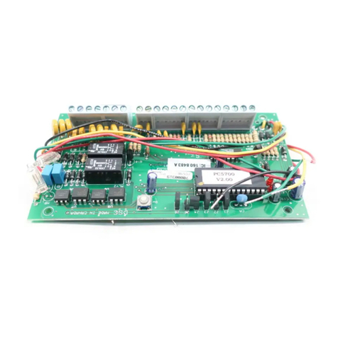
PC57OO
Fire Module
Zone # Zone Type Terminals
Zone 5 Class A (waterflow) A1+, A1–, B1+,B1–
circuit 1
Zone 6 Class A (waterflow) A2+, A2–, B2+,B2–
circuit 2
Zone 7 Ground fault EGND
detection zone
Zone 8 TLM fault
TIP2,RNG2,TIP1,
RNG1
The zone definitions for these four zones should
be as follows:
Zone 5 [07] Delayed Fire or [08] Standard Fire
Zone 6 [07] Delayed Fire or [08] Standard Fire
Zone 7 [08] Standard Fire
Zone 8 [09] 24Hr Supervisory (LINKS)
Jumpers J1-J6
Jumpers are used to determine which zones will be
assigned to the PC5700. Jumpers J1-J3 control the
NOTICE: The Canadian Department of Communications label identifies certified equipment. This certification means that the equipment meets certain telecommunications
network protective, operational and safety requirements. The Department does not guarantee the equipment will operate to the user’s satisfaction.
Before installing this equipment, users should ensure that it is permissible to be connected to the facilities of the local telecommunications company. The equipment must
also be installed using an acceptable method of connection. In some cases, the company’s inside wiring associated with a singleline individual service may be extended by
means of certified connector assembly (telephone extension cord). The customer should be aware that compliance with the above conditions may not prevent degradation
of service in some situations.
Repairs to certified equipment should be made by an authorized Canadian maintenance facility designated by the supplier. Any repairs or alterations made by the user to
this equipment, or equipment malfunctions, may give the telecommunications company cause to request the user to disconnect the equipment.
User should ensure for their own protection that the electrical ground connections of the power utility, telephone lines and internal metallic water pipe system, if present, are
connected together. This precaution may be particularly important in rural areas.
CAUTION: Users should not attempt to make such connections themselves, but should contact the appropriate electric inspection authority, or electrician, as appropriate.
The Load Number (LN) assigned to each terminal device denotes the percentage of the total load to be connected to a telephone loop which is used by the device, to
prevent overloading. The termination on a loop may consist of any combination of devices subject only to the requirement that the total of the Load Numbers of all the
devices does not exceed 100. REN: 0.1B
AVIS: L’étiquettedel’IndustrieCanadaidentifielematérielhomologué. Cetteétiquettecertifiequelematérielestconformeàcertainesnormesdeprotection,d’exploitationetdesécurité
des réseaux de télécommunications. Industrie Canada n’assure toutefois pas que le matériel fonctionnera à la satisfaction de l’utilisateur.
Avantd’installercematériel,l’utilisateurdoits’assurerqu’ilestpermisdeleraccorderauxinstallationsdel’entrepriselocaledetélécommunication. Lematérieldoitégalementêtreinstallé
ensuivantuneméthodeacceptéederaccordement.L’abonnénedoitpasoublierqu’ilestpossiblequelaconformitéauxconditionsénoncéesci-dessusn’empêchentpasladégradation
du service dans certaines situations.
Lesréparationsdematériel homologuédoiventêtreeffectuées paruncentred’entretien canadienautorisédésignépar lefournisseur. Lacompagniede télécommunications
peut demander à l’utilisateur de débrancher un appareil à la suite de réparations ou de modifications effectuées par l’utilisateur ou à cause de mauvais fonctionnement.
Pour sa propre protection, l’utilisateur doit s’assurer que tous les fils de mise à la terre de la source d’énergie électrique,les lignes téléphoniques et les canalisations d’eau
métalliques, s’il y en a, sont raccordés ensemble. Cette précaution est particulièrement importante dans les régions rurales.
AVERTISSEMENT: L’utilisateurnedoitpastenterdefairecesraccordementslui-même;ildoitavoirrecoursàunserviced’inspectiondesinstallationsélectriques,ouàunélectricien,
selon le cas.
L’indice de charge (IC) assigné a chaque dispositif terminal indique, pour éviter toute surcharge, le pourcentage de la charge totale qui peut être raccordée à un circuit téléphonique
bouclé utilisé par ce dispositif. La terminaison du circuit bouclé peut être constituée de n’importe quelle combinaison de dispositifs, pourvu que la somme des indices de charge de
l’ensemble des dispositifs ne dépasse pas 100. REN: 0.1B.
© 1997 Digital Security Controls Ltd.
1645 Flint Road, Downsview, Ontario, Canada M3J 2J6
Tel. (416) 665-8460 • Fax (416) 665-7498 • Tech. Line 1-800-387-3630
Printed in Canada 29002519 R0
Installation Instructions
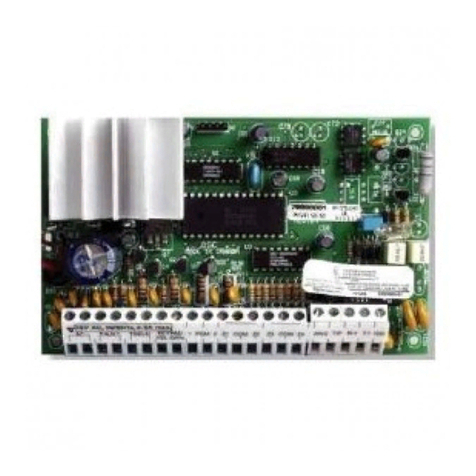
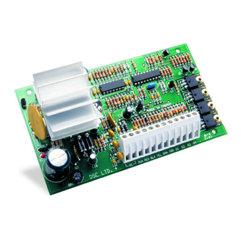
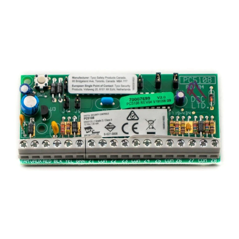
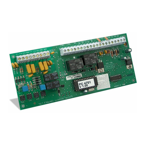
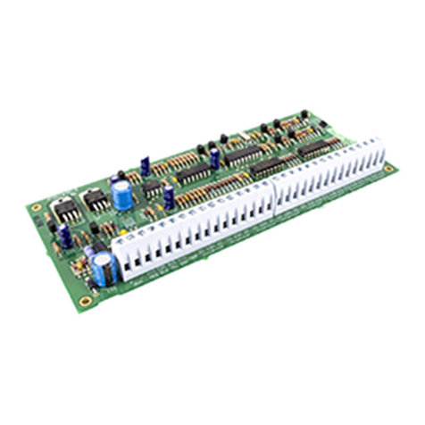
The PC5700 is a zone expansion module to be used with any control panel which supports the PC5108
module. In addition to four general purpose zone inputs, the module provides the following features: two
Class A supervisory waterflow zones, ground fault detection and dual-supervised telephone lines. The
PC5700 connects to a control panel via the 4-wire Keybus using standard 22-guage unshielded cable.
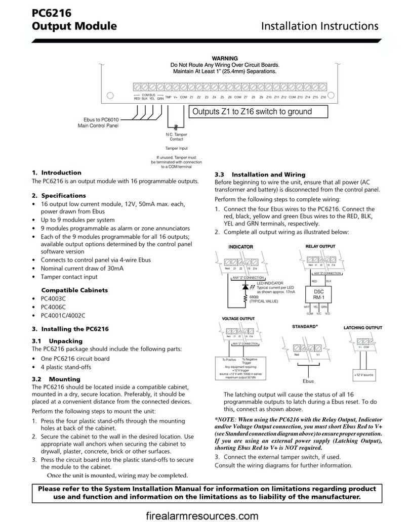
PC5700 Connection Diagram
Zone Inputs
The first four zone inputs (Z1-Z4) on the PC5700 are general purpose zones which can be programmed as
any zone type offered by the alarm control panel. The last four zone inputs are as follows:
first four PC5700 zones. Jumpers J4-J6 control the
second four PC5700 zones (two water-flow, ground
fault and TLM fault zones).
The connection diagram indicates the jumper set-
tings required to have the first four zones be zones
9-12 and the second four zones be zones 13-16.
To configure the PC5700 for other zone locations,
consult the following chart:
J1* J2* J3*
Zone Assignment J4** J5** J6**
None ON ON ON
Zones 9-12 ON OFF ON
Zones 13-16 OFF OFF ON
Zones 17-20 ON ON OFF
Zones 21-24 OFF ON OFF
Zones 25-28 ON OFF OFF
Zones 29-32 OFF OFF OFF
* PC5700 Z1-Z4
** PC5700 Z5-Z8
• W A R N I N G •
Please refer to the System Installation Manual for information on limitations regarding product
use and function and information on the limitations as to liability of the manufacturer.
