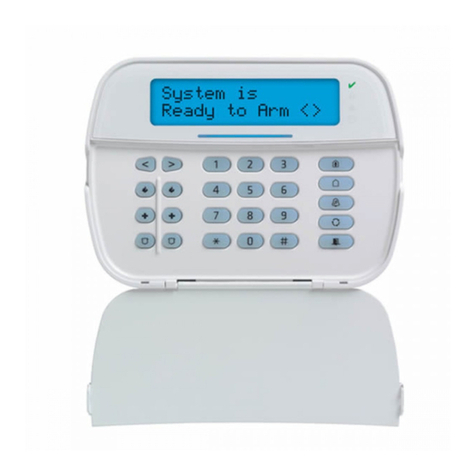
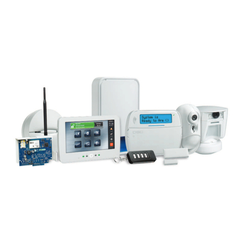
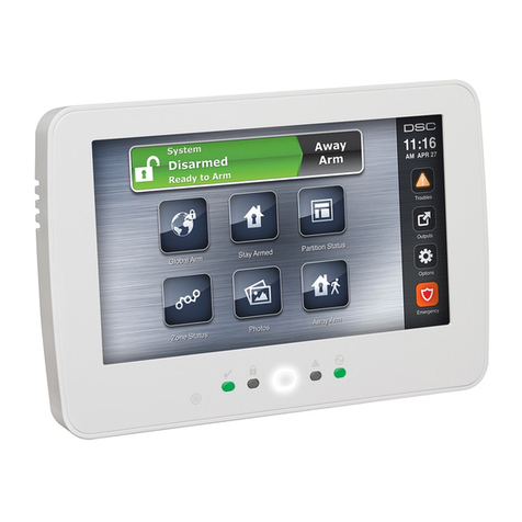
DSC PowerSeries Neo HS2128 E User manual

HS2016/HS2016-4/HS2032/HS2064/HS2064 E/HS2128/HS2128 E
Alarm Panel
User Manual
WARNING: This manual contains information on limitations regarding product use and function and information on
the limitations as to liability of the manufacturer. The entire manual should be carefully read.

1.0 Quick Reference 4
2.0 The PowerSeries Neo Security System 6
2.1 General System Operation 6
2.2 Carbon Monoxide Detection 6
2.3 Fire Detection 6
2.4 Testing Your System 6
2.5 Monitoring 7
2.6 Maintenance 7
3.0 Understanding Your Keypad 8
3.1 Icon and LED Keypad Symbols 8
3.2 Keypad Models 9
4.0 Securing the Premises 10
4.1 Arming the System 10
4.1.1 Arming the System (Infinite Exit Delay) 10
4.1.2 Away Arming the System with the Keypad 10
4.2 Stay Arming the System with the Keypad 11
4.2.1 Silent Exit Delay 11
4.3 Night Arming the System with the Keypad 12
4.4 No-Entry Arming 12
4.5 Leaving when the System is Armed - Quick Exit 13
4.6 Arming the System with a 2-Way Wireless Key 13
4.7 To Arm the System with a 2-way wireless key 13
4.8 Bypassing Zones 13
4.9 Bypass Groups 15
4.10 Arming Errors and Exit Faults 16
4.10.1 Arming Errors 16
4.10.2 Audible Exit Faults 16
4.11 Disarming the System 16
4.12 To Disarm the System with a Proximity Tag 17
4.13 Disarming Error 17
5.0 Emergency Keys 18
5.1 Alarms 18
5.1.1 Fire Alarm 18
5.1.1.1 Fire Alarm Bells Silenced 18
5.1.2 Carbon Monoxide Alarm 18
5.1.2.1 CO Alarm Bells Silenced 19
5.1.3 Intrusion (Burglary) Alarm - Continuous Siren 19
5.1.4 Alarm Cancel Window 19
5.1.5 Viewing Alarms in Memory 19
5.2 Resetting Smoke Detectors 19
6.0 Wireless Keys and other Devices 21
6.1 Using 2-way Wireless Keys 21
6.1.1 PG4929/PG8929/PG9929 21
6.1.2 PG4939/PG8939/PG9939 21
6.2 Using Proximity Tags 21
6.3 SMS Command and Control 22
6.3.1 Using the Keypad to Lookup the Number to Call for SMS Commands 22
6.3.2 Sending SMS Commands to your System 22
6.3.3 SMS Commands 22
6.3.4 SMS Responses from your System 23
7.0 Managing Users 24
7.1 Access Code Types 24
7.1.1 Opening the Access Code Menu 25
7.1.2 Adding, Changing and Deleting Access Codes 25
7.1.3 Enrolling and Deleting Proximity Tags 26
7.1.4 Editing User Labels 26
7.1.5 Assigning a Partition to a User code 27
7.2 Configuring Additional User Options 27
8.0 User Functions 28
8.1 Event Buffer 28
8.2 Setting the Time and Date 28
-2-

8.3 Enabling/Disabling the Auto Arm/Disarm Feature 28
8.4 Setting the Auto Arm Time 29
8.5 Allowing the Installer to Service your System Remotely - DLS 29
8.6 User Callup 29
8.7 Late to Open 29
8.8 Changing the Brightness of the LCD keypad 30
8.9 Changing the Contrast of the LCD keypad 30
8.10 Setting the Buzzer Volume 30
8.11 Setting the Voice Prompt Volume 31
8.12 Setting the Voice Chime volume 31
8.13 User's Walk Test 31
8.14 Trouble Conditions 32
9.0 Managing Partitions 36
9.1 Partitions 36
9.1.1 Single Partition Operation 36
9.1.2 Loaning a Keypad to Another Partition 36
9.2 Fire and CO Zone Types 37
10.0 Additional Features 38
10.1 Turning the Chime ON/OFF 38
10.2 Audio Verification 38
10.3 Visual Verification 38
10.3.1 System Lockout due to Invalid Attempts 38
10.4 Command Outputs 38
10.5 Burglary Verification 39
10.6 Swinger Shutdown 39
10.7 Call Waiting 39
10.8 Fire Alarm Verification 39
11.0 Safety Instructions 40
11.1 Regular Maintenance 40
12.0 Locating Detectors and Escape Plan 41
12.1 Smoke Detectors 41
12.2 Fire Escape Planning 42
12.3 Carbon Monoxide Detectors 42
13.0 Reference Sheets 43
13.1 System Information 43
13.2 Service Contact Information 43
13.3 Access Codes and Sensor / Zone Information 44
14.0 EULA 47
15.0 Installer Warning 48
16.0 EN50131 Compliance and Certification 49
17.0 Regulatory Information 50
-3-

Chapter 1
1.0 Quick Reference
The PowerSeries Neo Alarm System uses shortcut keys to access features on all models of keypads.
When using an LCD keypad, the PowerSeries Neo Alarm System uses a menu based navigation system.
The scroll keys can be used to navigate through the list of options contained within the current menu. For
more information see: 2.0 “Understanding your Keypad”. Look up detailed information on any of the lis-
ted actions using the accompanying Section number.
NOTE: Some features must be enabled by installer.
NOTE: Bypass Groups are not permitted in UL listed installations.
Status Lights Function
Keys
Emergency
Keys
Ready - Indicates system normal. Must be on to arm system. All zones must
be secured or bypassed and the system disarmed for this light to activate. Stay Arm Fire
Armed - Indicates system is armed . If the Ready light and the Armed light are
both on, an Exit Delay is in progress. Away
Arm Medical
Trouble - On indicates a system malfunction or tamper. Flashing indicates that
the keypad has a low battery condition. Follow the instructions displayed or
enter [*][2] to view trouble. Correcting the trouble turns off the indicator. Chime Panic
AC Power - Indicates AC Power is present. The AC Power light will turn off
when AC is absent. Reset
Sensors
Quick
Exit
Action Press Section
Away Arm for 2 seconds + [Access Code*] 3.1.2
Stay Arm for 2 seconds + [Access Code*] 3.2
Night Arm When armed in stay mode [*][1] + [Access Code*] 3.3
Disarm [Access Code] 3.1
No-Entry Arm-
ing
[*][9] + [Access Code*] 3.4
Quick Arm
/Quick Exit
[*][0] 3.5
Abort Arming
Sequence
[Access Code]
Bypassing - All bypass commands begin with [*][1] + [Access Code*]
Bypass Indi-
vidual Zones
[3 Digit Zone #] 3.7.1
Bypass All
Open Zones
[9][9][8] 3.7.1
Recall Last
Bypass
[9][9][9] 3.7.1
Clear Bypass [0][0][0] OR [Scroll] Bypass Options + [*] + [Scroll] Clear Bypasses + [*] 3.7.1
Program
Bypass Group
[3 digit zone #s] + [9][9][5] OR [3 digit zone #s] + [Scroll] Bypass Options
+ [*] + [Scroll] Prg Bypass Group + [*]
3.8
Load Bypass
Group
[9][9][1] OR [Scroll] Bypass Options + [*] + [Scroll] Bypass Group + [*] 3.8
Common Functions
Set Time and
Date
[*][6] [Master Code] + [0][1] 8.2
-4-

Chapter 1
Action Press Section
Turn Chime
ON/OFF
[*][4] + [Access Code*] OR 10.1
Change Bright-
ness [*][6] [Master Code] + [1][2] + 8.8
Change Con-
trast [*][6] [Master Code] + [1][3] + 8.8
Add/Delete
User
[*][5] + [Master Code] + [Access Code] + 1 7.0
Reset Smoke
Detectors
OR [*][7][2] 5.2
View Troubles [*][2] + [Access Code*] + 8.15
View Alarms [*][3] + [Access Code*] + 5.1.5
Perform System
Test [*][6] + [Master Code] + [0][4] + 4.4
Buzzer Volume [*][6] + [Master Code] + [1][4] + 8.10
-5-

Chapter 2
2.0 The PowerSeries Neo Security System
Your PowerSeries Neo has been designed to provide you with the greatest possible flexibility and con-
venience. Read this manual carefully and have your installer instruct you on how to operate your system
and which features have been implemented in your system. All users of this system should be equally
instructed in its use. Fill out section "System Information" with all of your zone information and access
codes and store this manual in a safe place for future reference.
NOTE: The PowerSeries Neo security system includes specific false alarm reduction features and is clas-
sified in accordance with ANSI/ SIA CP-01-2010 Control Panel Standard - Features for False Alarm
Reduction. Please consult your installer for further information regarding the false alarm reduction fea-
tures built into your system as all are not covered in this manual.
2.1 General System Operation
Your security system is made up of a PowerSeries Neo control panel, one or more keypads and various
sensors and detectors. The control panel will be mounted out of the way in a utility closet or in a base-
ment. The metal cabinet contains the system electronics, fuses and standby battery.
All the keypads have an audible indicator and command entry keys. LED keypads have a group of zone
and system status lights. LCD keypads have an alphanumeric liquid crystal display (LCD). The keypad is
used to send commands to the system and to display the current system status. The keypad(s) will be
mounted in a convenient location inside the protected premises close to the entry/exit door(s). The secur-
ity system has several zones of area protection and each of these zones is connected to one or more
sensors (motion detectors, glassbreak detectors, door contacts, etc.). A sensor in alarm is indicated by
the corresponding zone lights flashing on an LED keypad or by messages on the LCD keypad.
NOTE: Only the installer or service professional shall have access to the control panel.
2.2 Carbon Monoxide Detection
This equipment is capable of monitoring carbon monoxide detectors and providing a warning if carbon
monoxide is detected. Please read the Family Escape Planning guidelines in this manual and instruc-
tions that are available with the carbon monoxide detector.
NOTE: Must be enabled and configured by installer.
NOTE: The equipment should be installed in accordance with NFPA 720.
2.3 Fire Detection
This equipment is capable of monitoring fire detection devices such as smoke detectors and providing a
warning if a fire condition is detected. Good fire detection depends on having adequate number of detect-
ors placed in appropriate locations. This equipment should be installed in accordance with NFPA 72
(N.F.P.A., Batterymarch Park, Quincey MA 02269). Carefully review the Family Escape Planning
guidelines in this manual.
NOTE: Must be enabled and configured by installer.
2.4 Testing Your System
Tests all system keypad LEDs, keypad sounders, bells and/or sirens. To ensure that your system con-
tinues to function as intended, you must test your system weekly.
IMPORTANT: For UL HOME HEALTH CARE listed applications the system shall also be tested weekly
without AC power. To remove AC from the control unit, remove the screw from the restraining tab of the
plug in adapter and remove the adapter from AC outlet. After completing the test of the unit using only the
battery backup source, reconnect the plug in adapter and attach the screw through the restraining tab so
that the adapter is securely attached to the outlet.
IMPORTANT: Should your system fail to function properly, contact your installation company.
IMPORTANT: All smoke detectors must be tested by your smoke detector installer once per year.
To Perform a Keypad and Siren Test LCD Display
1. From the Ready state press [*][6] and enter the [Master Code] to
access User Functions.
Press (*) for <>
User Functions
2. Press [04] or use the scroll keys to navigate to System Test and
press [*]. The system activates all keypad sounders, bells/sirens and
keypad LEDs for two seconds.
Press (*) for <>
System Test
-6-
Chapter 2
3. To go back to the Ready state press [#].
NOTE: If your system has PIR cameras enrolled, two images from each PIR camera are sent to the mon-
itoring station during a system test.
2.5 Monitoring
This system is capable of transmitting alarms, troubles and emergency information. If you initiate an
alarm by mistake, immediately call the central station to prevent an unnecessary response.
NOTE: For CP-01 systems, the monitoring function must be enabled by the installer before it becomes
functional. There is a communicator delay of 30 seconds in this control panel. It can be removed, or it can
be increased up to 45 seconds, at the option of the end-user by consulting with the installer.
2.6 Maintenance
With normal use, the system requires minimum maintenance. Note the following points:
lDo not wash the security equipment with a wet cloth. Light dusting with a slightly moistened cloth
should remove normal accumulations of dust.
lUse the system test described in “Testing Your System” to check the battery condition. We recom-
mend, however, that the standby batteries be replaced every 3-5 years.
lFor other system devices such as smoke detectors, passive infrared, ultrasonic or microwave
motion detectors or glassbreak detectors, consult the manufacturer’s literature for testing and
maintenance instructions.
-7-

Chapter 3
3.0 Understanding Your Keypad
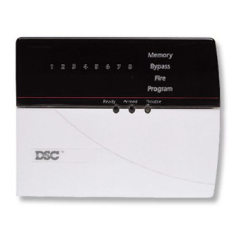
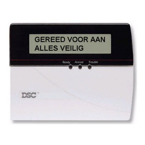
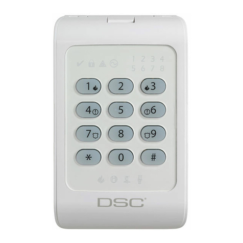
The PowerSeries Neo Alarm System supports a variety of wireless, hardwired and proximity sensor LCD,
LED and Icon keypads. All keypads come equipped with the LED status lights described in section 1
"Quick Reference". HS2LCD series keypads display system messages on their LCD screen. HS2ICN
series keypads display messages, as described in the following section. HS2LED series keypads display
messages via a series of numbered LEDs, as described in the following section. All keypad versions will
have a solid blue LED bar that is always on except when, if enrolled, a proximity tag is presented and suc-
cessfully read by the keypad.
3.1 Icon and LED Keypad Symbols
HS2ICN Series HS2LED Series
596
12 710
11
1
8
15
234
17
16
14
13
5
9
7
6
1. Clock Digits 1, 2 These clock digits indicate the hour when the local clock is active. Digit 2 is
also used to identify the zone number.
2. : (Colon) This icon is the hours/minutes divider and will flash once per second when
the local clock is active.
3. Clock Digits 3, 4 These are the minute digits when the local clock is active. The digits 3 and
4 are used to indicate the zone number for open zones or alarm in
memory. These two digits combined with the clock digit 2, scroll one zone
per second from the lowest number to the highest, when scrolling through
zones.
4. 1 to 8 These numbers identify troubles when [*][2] is pressed.
5. Memory Indicates that there are alarms in memory.
6. Bypass Indicates that there are zones bypassed.
7. Program Indicates that the system is in Installer or User's programming, or that the
keypad is busy, and the LED will flash. If an Access Code is required,
while accessing [*] menus, this LED is ON and solid to indicate that the
code is required.
8. Away Indicates that the panel is armed in the Away Mode.
9. Fire Indicates that there are fire and/or CO alarms in memory.
10. Stay Indicates that the panel is armed in the Stay Mode.
11. Chime This icon turns on when the Chime function key is pressed to enable Door
Chime on the system. It will turn off when the chime function key is pressed
again to disable Door Chime.
12. OPEN This icon is used with clock digits 1 and 2 to indicate activated zones (not
alarm) on the system. When zones are opened, the OPEN icon will turn on,
clock digits 1 and 2 will scroll through the violated zones.
13. AC Indicates that AC is present at the main panel.
14. System Trouble Indicates that a system trouble is active.
15. Night Indicates that the panel is armedin the Night Mode.
16. Ready Light (green) If the Ready light is on, the system is ready for arming. If the toggle of the
Ready LED flashes for Force Arming enabled, the LED flashes with force
armable zones open on the partition.
17. Armed Light (red) If the Armed light is on, the system has been armed successfully.
NOTE: For UL listed installations, zones can only be bypassed manually.
-8-

Chapter 3
3.2 Keypad Models
NOTE: In the following list if x = 9 (the system operates in 912-919MHz), x=4 (the system operates in
433MHz band) or x=8 (the system operates in 868MHz band). Only models operating in 912-919MHz
band are UL/ULC listed.
HS2LCD Alphanumeric LCD keypad
HS2LCDP Alphanumeric LCD keypad with Prox. Tag support
HS2ICN Icon keypad
HS2ICNP Icon keypad with Prox. Tag support
HS2LED LED keypad
HS2LCDRFx Alphanumeric LCD keypad with wireless receiver
HS2LCDRFPx Alphanumeric LCD keypad with wireless receiver and Prox. tag support
HS2ICNRFx Icon keypad with wireless receiver
HS2ICNRFPx Icon keypad with wireless receiver and Prox. tag support
HS2LCDWFx Wireless Alphanumeric LCD keypad
HS2LCDWFPx Wireless Alphanumeric LCD keypad with Prox. Tag support
HS2LCDWFPVx Wireless Alphanumeric LCD keypad with Prox. Tag support & Voice Promp
HS2TCHP Touchscreen keypad. For additional information, refer to the HS2TCHP Touchscreen
User Manual.
-9-

Chapter 4
4.0 Securing the Premises
The PowerSeries Neo provides multiple arming modes as described below:
Away mode Use when no one in your household will be home. Away mode activates all peri-
meter and interior sensors in the alarm system.
Stay mode Use this mode when you are staying home, but expect someone to use the entrance
door later. Stay mode partially activates your alarm system by arming all perimeter
sensors and bypassing all interior sensors.
Night mode Use when you want the perimeter and interior armed but would like to allow limited
movement in your house without activating the alarm. (e.g., disable motion sensors
in an area containing bedrooms and a washroom). Night mode is similar to Stay
mode but only bypasses internal sensors configured as Night Zones.
NOTE: Verify with your alarm company which modes are available on your system. For SIA FAR listed
panels, the Stay Arming Exit Delay will be twice as long as the Away Arming Exit Delay.
Depending on your system configuration, there are multiple methods you can use to arm your system.
You can arm the system using a:
lKeypad
l2-way wireless key
See also:
lSilent Exit Delay
4.1 Arming the System
The PowerSeries Neo system can be set/armed using a keypad, a 2-way wireless key or a proximity tag.
4.1.1 Arming the System (Infinite Exit Delay)
In an attempt to reduce false alarms, your system is designed to notify you of an improper exit when arm-
ing the system. When using the Push to Set, or Final Door Set feature, attempting to arm your system will
start an infinite exit delay. The keypad will sound a beep once per second. When you have opened and
closed the final exit door, or after pressing the Push to Set button, the exit delay will be reduced to a pro-
grammable value, which is typically 10 seconds, after which the alarm will complete the setting. The
panel used this time period to allow time for the detectors on the system to return to their normal state.
When this time expires, the system checks for detectors/windows/doors that may be open. If any of these
are open, the panel will cancel the arming. If this occurs, you must re-enter the premises, check the sys-
tem, close any open zones, and then attempt to arm again.
4.1.2 Away Arming the System with the Keypad
Away mode activates the complete alarm system by:
lArming all perimeter sensors.
lArming all interior sensors.
To Arm the System in Away Mode: LCD Display
1. Ensure all windows and doors are closed and that the Ready indic-
ator is on.
Date Time
JAN 02/18 2:06a
2. To arm using the Away key , press and hold the Away key for 2
seconds and, if required, enter your [access code] or present your
proximity tag.
OR
To Quick Arm the system press [*][0].
System is
Ready to Arm
then
Present Tag or
Enter Code
3. If zones have been bypassed, ICN or LED keypads bypass LED
will light and the bypassed zones #s will be shown. On an LCD
keypad a warning appears.
* Warning *
Bypass Active
-10 -

Chapter 4
4. After successfully initiating the arming sequence the:
lArmed indicator turns on.
lReady indicator remains lit.
lExit Delay timer begins counting down.
lKeypad beeps six times, continues beeping once per second
until beeping rapidly in the final ten seconds.
lThe system may be configured to have a persistent exit delay that
only ends when the exit door is opened and closed, or when a
button is pressed outside the protected premises.
Exit Delay in
Progress
5. To cancel the arming sequence, enter your [access code] or present
your proximity tag to the keypad reader.
System Disarmed
No Alarm Memory
6. Once the exit delay timer expires, thereby arming the system, the:
lReady indicator turns off.
lArmed indicator remains on.
lKeypad stops sounding.
System Armed
in Away Mode
NOTE: The installer configures the exit delay timer and whether or not an access code is required for arm-
ing the system.
4.2 Stay Arming the System with the Keypad
Stay mode partially activates your alarm system by:
lArming all perimeter sensors.
lBypassing all interior sensors.
To Arm the System in Stay mode: LCD Display
1. Ensure all windows and doors are closed and that the Ready indicator
is on.
Date Time
JAN 02/18 2:06a
2. Press and hold the Stay key for 2 seconds and, if required, enter your
access code or present your proximity tag. Do not leave the premises.
System is
Ready to Arm
then
Enter Your
Access Code
3. If zones have been bypassed, ICN or LED keypads bypass LED will
light and the bypassed zones numbers will be shown. On an LCD
keypad a warning appears.
* Warning *
Bypass Active
4. After successfully initiating the arming sequence the:
lArmed indicator turns on.
lReady indicator remains lit.
lExit Delay timer begins counting down.
Exit Delay in
Progress
5. To cancel the arming sequence, enter your [access code] or present
your proximity tag.
System Disarmed
No Alarm Memory
6. Once the exit delay timer expires, thereby arming the system, the:
lReady indicator turns off.
lArmed indicator remains on.
lBypass or system indicator activates.
System Armed
in Stay Mode
NOTE: When using a proximity tag and a Stay/Away zone is programmed, the system arms in Away
mode if a delay zone is tripped. If there is no Stay/Away zone, the system always arms in Away mode.
4.2.1 Silent Exit Delay
If the system is armed using the Stay key or the No Entry Arming method [*][9]:
lThe warning beep is silenced.
lThe exit time is doubled for that exit period only (CP-01 versions only).
NOTE: For non CP-01 versions, Standard Exit Time is used.
-11 -

Chapter 4
4.3 Night Arming the System with the Keypad
Night mode partially activates the alarm system by:
lBypassing all internal sensors configured as Night zones.
lArming all perimeter sensors.
lArmingall other internal sensors.
Arming the system in Night mode is possible after the system has first been armed in Stay mode and [*][1]
is pressed at the keypad. The keypad can also be configured with a function key to arm the system in
Night mode. To access armed interior areas when the system is armed in Night Mode, you must disarm
the system.
NOTE: Ensure that your installer has provided you with a list identifying all programmed night zones.
Your installer can configure a function key to arm the panel in Night mode without the system already
being armed in Stay mode.
To Arm the System in Night mode: LCD Display
1. If configured, press and hold the Night Arm key for 2 seconds. OR
2. Once the system is armed in Stay mode (Armed indicator is on) at
any keypad press [*][*].
OR
press[*][1].
Date Time
JAN 02/19 2:06a
then
Press (*) for <>
Interior Arm
3. If required, enter your access code. All interior zones will be armed,
except for devices programmed as Night Zones.
lThe Night Mode icon turns on.
Present Tag or
Enter Code
then
Interior Has
Been Armed
To gain access to interior areas that are armed during Night mode disarm the system by entering your
[access code].
4.4 No-Entry Arming
No-Entry Arming arms the system in Stay mode by:
lRemoving the Entry Delay from all configured zones.
lArming all perimeter sensors.
lBypassing all interior sensors.
An entry through any zone will create an instant alarm.
To arm the system in No-Entry mode: LCD Display
1. Check that the Ready indicator is on and your system is ready to
be armed.
Date Time
JAN 02/18 2:06a
2. Press [*][9] and, if required, enter your [access code]. Present Tag or
Enter Code
3. If zones have been bypassed, ICN or LED keypads bypass LED will
light and the bypassed zones #s will be shown. On an LCD keypad
a warning appears.
* Warning *
Bypass Active
then
4. After successfully initiating the arming sequence the:
lArmed light flashes as a reminder that the system is armed and
has no entry delay.
lKeypad sounds fast beeps.
lKeypad displays “Exit Delay in Progress”.
Armed With No
Entry Delay
then
Exit Delay in
Progress
5. To cancel the arming sequence, enter your [access code] or present
your proximity tag.
System Disarmed
No Alarm Memory
6. Once the exit delay timer expires, the system is armed. System Armed
in Stay Mode
-12 -

Chapter 4
4.5 Leaving when the System is Armed - Quick Exit
Use the Quick Exit feature if the system is already armed and you would like to leave without disarming
and rearming the system. Quick Exit uses the same hot keys as Quick Arming, and it provides you with a
two minute exit delay to leave the premises without triggering an alarm. Once the door you leave from
closes, the quick exit timer will be canceled.
To Quick Exit:
LCD Display
1. When the system is already armed and the Armed light is lit, press
and hold the Quick Exit key for 2 seconds
OR
press [*][0].
Quick Exit in
Progress
2. Exit the premises before the exit delay timer expires. After exiting, the
delay timer will be canceled.
4.6 Arming the System with a 2-Way Wireless Key
If configured, the PowerSeries Neo system can be armed using the following wireless keys:
lPG4929/PG8929/PG9929
lPG4939/PG8939/PG9939
4.7 To Arm the System with a 2-way wireless key
Press the desired Arming mode button anytime the system Ready indicator is on.
4.8 Bypassing Zones
WARNING! If a zone is not operating properly contact a service person immediately.
Bypassing zones intentionally unprotects specified zones the next time your system is armed. Depending
on the type of keypad, bypassed zones will be identified differently. Using an HS2LCD series keypad,
bypassed zones are indicated on the LCD screen as shown in the following table. If using an LED or ICN
series keypad, the Bypass indicator will light and the bypassed zones numbers will be displayed.
LCD Display Indication Description
Zone Label <>
none Zone is ready for arming.
Zone Label <>
O
O Zone is currently open. You may be unable to arm the
system.
Zone Label <>
B
B Zone is bypassed.
LCD Keypad Zone Indications
Bypassed zones:
lMust be configured before arming the system.
lCan be done using a keypad or SMS.
lAllow for access to protected areas when the system is armed.
lAllow you to arm the system if a zone is temporarily out of service.
lReduce the level of security.
lWill not sound an alarm.
lAre automatically cancelled each time the system is disarmed.
lCan be programmed together within bypass groups. For more information see “Bypass Groups”.
Recall Last
Bypass
Recalls zones that were previously bypassed.
Bypass All Open
Zones
Allows the user to quickly bypass all open zones with a single command.
Clear Bypass Instantly clears all bypass conditions from the zones assigned to the partition.
-13 -

Chapter 4
Programming a
Bypass Group
Use when you consistently bypass the same zones. This feature allows you to store
in memory one group of bypassed zones per partition.
Activating a
Bypass Group
Loads a stored bypass group from memory.
NOTE: Ensure that no zones are unintentionally bypassed when arming your system.
NOTE: 24-hour zones can only be unbypassed manually.
NOTE: For security reasons, your installer has programmed the system to prevent you from bypassing
certain zones (e.g., smoke detectors). For more information on fire zones see “Fire and CO Zone Types”.
To bypass individual zones: LCD Display
1. Press [*] to enter the function menu. Press (*) for <>
Zone Bypass
2. Press [*] or [1]. If required enter your [access code] or present your
proximity tag.
Zone Bypass <>
(*) To Bypass
3. Directly bypass zones by entering their [3 digit zone #]. If using an
LCD keypad press [*].
OR
Scroll to the desired zone using the scroll keys and press [*].
Zone 1 <>
0
4. To toggle and unbypass a zone reenter the [3 digit zone #] or press
[*] again. To bypass more zones repeat steps 3 and 4.
Zone 1 <>
B
5. To exit bypassing mode press [*].
6. If using an LED or ICN series keypad, the zone LED will light and
the bypassed zone #s will be shown. If the system is ready to arm
the Ready indicator will be lit. When arming the system the following
message briefly displays.
* Warning *
Bypass Active
To bypass all open zones: LCD Display
1. Press [*] to enter the function menu. Press (*) for <>
Zone Bypass
2. Press [*] or [1]. If required enter your [access code] or present your
proximity tag.
Zone Bypass <>
(*) To Bypass
3. Press [9][9][8]
OR
Scroll to Bypass Options using the keys [<] [>] and press [*]. Scroll to
Bypass Op Zones and press [*].
Press (*) for <>
Bypass Options
Press (*) for <>
Bypass Op. Zones
Bypassed Open
Zones
4. To exit bypassing mode, press [*].
5. If using an LED or ICN series keypad, the will light and the
bypassed zone #s will be shown. If the system is ready to arm the
Ready indicator will be lit. When arming the system the following
message briefly displays.
To recall the last bypassed zones: LCD Display
1. Press [*] to enter the function menu. Press (*) for <>
Zone Bypass
2. Press [*] or [1]. If required enter your [access code] or present your
proximity tag.
Zone Bypass <>
(*) To Bypass
-14 -

Chapter 4
3. Press [9][9][9]
OR
Scroll to Bypass Options and press [*]. Scroll to Bypass Recall using
the scroll keys and press [*].
Press (*) for <>
Bypass Recall
then
Bypass Recalled
Zones Bypassed
4. To exit bypassing mode press [*].
5. If using an LED or ICN series keypad, the will light and the
bypassed zone #s will be shown. If the system is ready to arm the
Ready indicator will be lit. When arming the system the following
message briefly displays.
* Warning *
Bypass Active
To clear the bypass indication from all zones: LCD Display
1. Press [*] to enter the function menu. Press (*) for <>
Zone Bypass
2. Press [*] or [1]. If required enter your [access code]. Zone Bypass <>
(*) To Bypass
3. Press [0][0][0]
OR
Scroll to Clear Bypasses using the [<][>] keys and press [*]. All
bypassed zones will now be open.
Press (*) for <>
Clear Bypasses
then
Bypass Cleared
Zones Unbypassed
4. To exit bypassing mode press [*].
4.9 Bypass Groups
Program frequently bypassed zones into the system as a bypass group. Using bypass groups avoids indi-
vidually bypassing each zone. One bypass group can be programmed per partition.
NOTE: This feature is not to be used in UL listed installations.
To program a Bypass Group: LCD Display
1. Press [*] to enter the function menu. Press (*) for <>
Zone Bypass
2. Press [*] or [1]. If required enter your [access code]. Scroll to <>
Bypass Zones
3. Enter the 3 digit zone # of the zones you want bypassed
OR
Scroll to and press [*] to indicate all zones you want bypassed.
Upstrs H Wdw <>
B
4. Press [9][9][5] to program the bypass group with the currently
bypassed zones
OR
Scroll to Bypass Options using the scroll keys and press [*]. Scroll to
Prg Bypass Group and press [*].
Press (*) for <>
Prg Bypass Group
5. The Bypass Group is now programmed. The keypad will beep three
times.
Bypass Group
Programmed
6. To exit bypassing mode and return to the Ready state, press . System is
Ready to Arm
To load a Bypass Group: LCD Display
1. Press [*] to enter the function menu. Press (*) for <>
Zone Bypass
2. Press [*] or [1]. If required enter your [access code]. Scroll to <>
Bypass Zones
-15 -

Chapter 4
3. Press or [9][9][1]. If required enter your [access code].
OR
Scroll to Bypass Options using the [<][>] keys and press [*]. Scroll to
Bypass Group and press [*].
Press (*) for <>
Bypass Group
4. The group of zones are now bypassed. The following message
briefly displays.
Bypass Group
Zones Bypassed
5. To exit bypassing mode and return to the Ready state, press [*].
6. If using an LED or ICN series keypad, the will light and the
bypassed zones #s will be shown. If the system is ready to arm the
Ready indicator will be lit. When arming the system the following
message briefly displays.
* Warning *
Bypass Active
4.10 Arming Errors and Exit Faults
The PowerSeries Neo audibly notifies you of any errors when you are attempting to arm the system or
exit the premises.
4.10.1 Arming Errors
An error tone (long beep) sounds if the system is unable to arm. Arming errors occur if:
lThe system is not ready to arm (i.e., sensors are open).
lAn incorrect user code is entered.
lA trouble is present and has not been viewed by the user. This operation must be enabled by the
installer.
To Correct an Arming Error
1. Ensure all sensors are secure. Your keypad will identify all open zones.
2. If the trouble light is on, enter [*][2] and enter [99] or scroll to the Acknowledge All Troubles prompt
and press [*], if your installer has configured your system to impede armingwhen a trouble is present.
3. Try arming the system again. For details on arming the system, see one of the previous arming pro-
cedures.
4. If errors persist contact your installer.
4.10.2 Audible Exit Faults
NOTE: Must be enabled by installer.
In an attempt to reduce false alarms, the Audible Exit Fault notifies you of an improper exit when arming
the system. Improper exits are caused by failing to securely close the Exit/Entry door.
Improper exits cause the following system notifications:
lThe keypad emits one continuous beep.
lThe bell or siren sounds for the duration of the entry delay until a valid user code is entered or
until the programmed Bell time out expires.
To correct an exit fault:
1. Re-enter the premises.
2. Disarm the system before the entry delay timer expires by entering your [access code].
3. Follow the Away arming procedure again, making sure to close the entry/exit door properly. For
more details see: “Away Arming the System with the Keypad”.
4.11 Disarming the System
Depending on your system configuration, there are multiple methods you can use to disarm/unset your
system. You can disarm the system using a 2-way wireless key or a proximity tag:
To disarm the system with a keypad:
1. Enter your [access code] or present your proximity tag anytime the system is armed. (Armed
indicator is on).
2. If you walk through the entry door, the keypad will beep. Disarm within _____ seconds to avoid an
alarm condition.
To disarm the system with a 2-way wireless key:
1. Press the disarm button anytime the system is armed. (Armed indicator is on).
-16 -

Chapter 4
2. If you walk through the entry door the keypad will beep. Press the disarm button within ____
seconds to avoid an alarm condition.
NOTE: After disarming a system with an HS2LCD keypad using a 2-way wireless key, always check the
alarm memory to determine if any alarms have occurred during the armed period.
4.12 To Disarm the System with a Proximity Tag
1. Present your proximity tag to a keypad equipped with a proximity sensor anytime the system is
armed . (Armed indicator is on) and if configured as required, enter your access code.
2. If you walk through the entry door the keypad will beep. Present your proximity tag within
_____ seconds to avoid an alarm condition.
NOTE: Duration of Entry timer is programmed by installer. The installer will advise the maximum duration
of entry delay that was programmed in the system. It cannot exceed 45 seconds.
4.13 Disarming Error
If your code is invalid, the system will not disarm and a 2-second error tone will sound. If this occurs,
press [#] and re-enter your access code.
-17 -

Chapter 5
5.0 Emergency Keys
IMPORTANT: EMERGENCY USE ONLY!
Pressing both the emergency keys generates a Fire, Medical, or Panic Alarm, and alerts the monitoring
station. e.g., to generate a medical alarm press both of the medical alarm keys for 2 seconds and the dis-
play on an LCD keypad will show Hold down keys for Med. Alarm.The keypad beeps to indicate that the
alarm input has been accepted and sent to the monitoring station.
Fire Alarm
Medical Alarm
Panic Alarm
NOTE: Verify with your alarm company that your system is equipped with emergency keys.
NOTE: Fire keys can be disabled by the installer.
NOTE: Having an optional audio verification module installed in your system allows the monitoring sta-
tion to open 2-way communication when notified of an alarm.
5.1 Alarms
The system can generate different alarm sounds, each with a different purpose and priority.
Priority Type of Alarm What you hear
1 Fire Temporal (3 beeps then a pause) or
pulsed siren (continuous beeping)
2 Carbon Monox-
ide
4 beeps, 5 second pause, 4 beeps
3 Intrusion (Burg-
lary)
Continuous siren
4 Flood 1 second on, 3 seconds off, repeating
Alarm Types
NOTE: Medical alarm is silent, it only results in an alarm transmission to the monitoring station.
5.1.1 Fire Alarm
Follow your emergency evacuation plan immediately!
If the Fire Alarm was Accidental (e.g., burnt toast, bathroom steam, etc.)
1. Enter your Access Code to silence the alarm.
2. Call your central station to avoid a dispatch.
NOTE: Verify with your alarm company that your system is equipped with fire detection.
For information on resetting smoke detectors see: “Resetting Smoke Detectors”.
5.1.1.1 Fire Alarm Bells Silenced
Fire alarms can be silenced by entering a valid access code. The mes-
sage shown will be displayed on a LCD or touch screen keypad. The
message will not be cleared until all the fire zones zones have been
restored on system.
Fire Alarm < >
Bells Silenced
5.1.2 Carbon Monoxide Alarm
WARNING! Carefully review your Carbon Monoxide Alarm Installation/User Guide to determine the
necessary actions required to ensure your safety and ensure that the equipment is operating cor-
rectly. Incorporate the steps outlined in the guide into your evacuation plan.
Activation of your CO alarm indicates the presence of carbon monoxide (CO), which can be fatal. During
an alarm:
lThe red LED on the CO detector flashes rapidly and buzzer sounds with a repeating cadence of 4
quick beeps, 5-second pause, 4 quick beeps.
lThe siren connected to the control panel produces the same cadence as above.
lThe keypad provides audible and visual indication of the CO alarm.
-18 -

Chapter 5
If the Carbon Monoxide Alarm Sounds
1. Operate Silence button.
2. Call emergency services or your fire department.
3. Immediately move outdoors or to an open door/window.
5.1.2.1 CO Alarm Bells Silenced
CO alarms can be silenced by entering a valid access code. The mes-
sage shown will be displayed on a LCD or touch screen keypad. The
message will not be cleared until CO zones have been restored on sys-
tem.
CO Alarm < >
Bells Silenced
5.1.3 Intrusion (Burglary) Alarm - Continuous Siren
!
If you are unsure of the source of the alarm approach with caution!
If the Intrusion alarm was accidental
1. Enter your Access Code to silence the alarm. If the code is entered within 30s (or the programmed
value of the alarm transmission delay) the transmission of the alarm to the monitoring station will be
cancelled.
2. Call your central station to avoid a dispatch.
5.1.4 Alarm Cancel Window
The control panel provides a period of time in which the user can cancel the alarm transmission. If the
programmed alarm transmission delay has expired, canceling an alarm sends a message to the mon-
itoring station. Upon a successful transmission of the cancellation message the keypad will beep 6 times.
NOTE: Must be enabled and configured by installer.
NOTE: For CP-01 systems, alarm transmission delay must not exceed 45 seconds.
5.1.5 Viewing Alarms in Memory
When an alarm occurs the keypad indicator illuminates. Viewing the Alarm memory provides more inform-
ation on the sensor(s) that were tripped. When using an ICON or LED keypad the Memory LED will be lit
and the zone numbers will be displayed.
To View Alarms in Memory LCD Display
lPress [*][3] or
use the scroll keys to navigate to Alarm Memory and press . The
Alarm information will display. For more information on the mes-
sages that could be displayed see: “Alarm Messages”.
Press (*) for <>
Alarm Memory
Alarm Messages
LCD Display What it means
Burglary <>
Verified
Multiple burglary sensors were tripped. Central station has been noti-
fied.
Burglary Not <>
Verified
A single burglary sensor was tripped. Central station has been noti-
fied.
Hold-up <>
Verified
Multiple hold-up sensors were tripped. Central station has been noti-
fied.
Hold-up Not <>
Verified
A single hold-up sensor was tripped.
Fire Alarm <>
Fire Zone 1
Fire alarm has been triggered. Central station has been notified. On
an ICN or LED keypad the will be lit.
CO Alarm <>
CO Zone 1 <>
CO alarm has been triggered. Central station has been notified. On
an ICN or LED keypad the will be lit.
-19 -

Chapter 5
NOTE: Verify with your alarm company if this function is required on your system.
To Reset the Sensors
1. Press and hold on the keypad for 2 seconds. If the reset is successful, the alarm is cancelled.
2. If a smoke detector fails to reset, it may still be detecting an alarm condition. If unsuccessful, the
alarm will reactivate or continue.
-20 -
5.2 Resetting Smoke Detectors
After having detected an alarm condition smoke detectors require a reset to exit the alarm condition.
This manual suits for next models
7
Table of contents
Other DSC Security System manuals

DSC
DSC PC5928 Installation instructions

DSC
DSC Power8 PC5OO5 User manual

DSC
DSC LCD5501Z32-433 NA User manual

DSC
DSC PowerSeries PC4020 User manual

DSC
DSC Power Series User manual

DSC
DSC PowerSeries Neo User manual

DSC
DSC Neo User manual

DSC
DSC PowerSeries RFK5500 User manual

DSC
DSC LCD5501Z User manual

DSC
DSC PG4975 Manual
Popular Security System manuals by other brands

eltech
eltech GsmAlarm-500E instruction manual

M2M
M2M MQ03-Alarm Installer manual

Easywave
Easywave RTS26 STATUS Series quick start guide

BT Redcare
BT Redcare 3GSTU-12V User's installation guide

Konlen
Konlen KL-H21B Installation and user guide

Gems
Gems Warrick RA-431 Series Installation and Operation Bulletin