Dune HD Solo 4K User manual

1
Dune HD Solo 4K / Duo 4K
Z-Wave Smart Home Controller
User Manual

2
INTRODUC TION
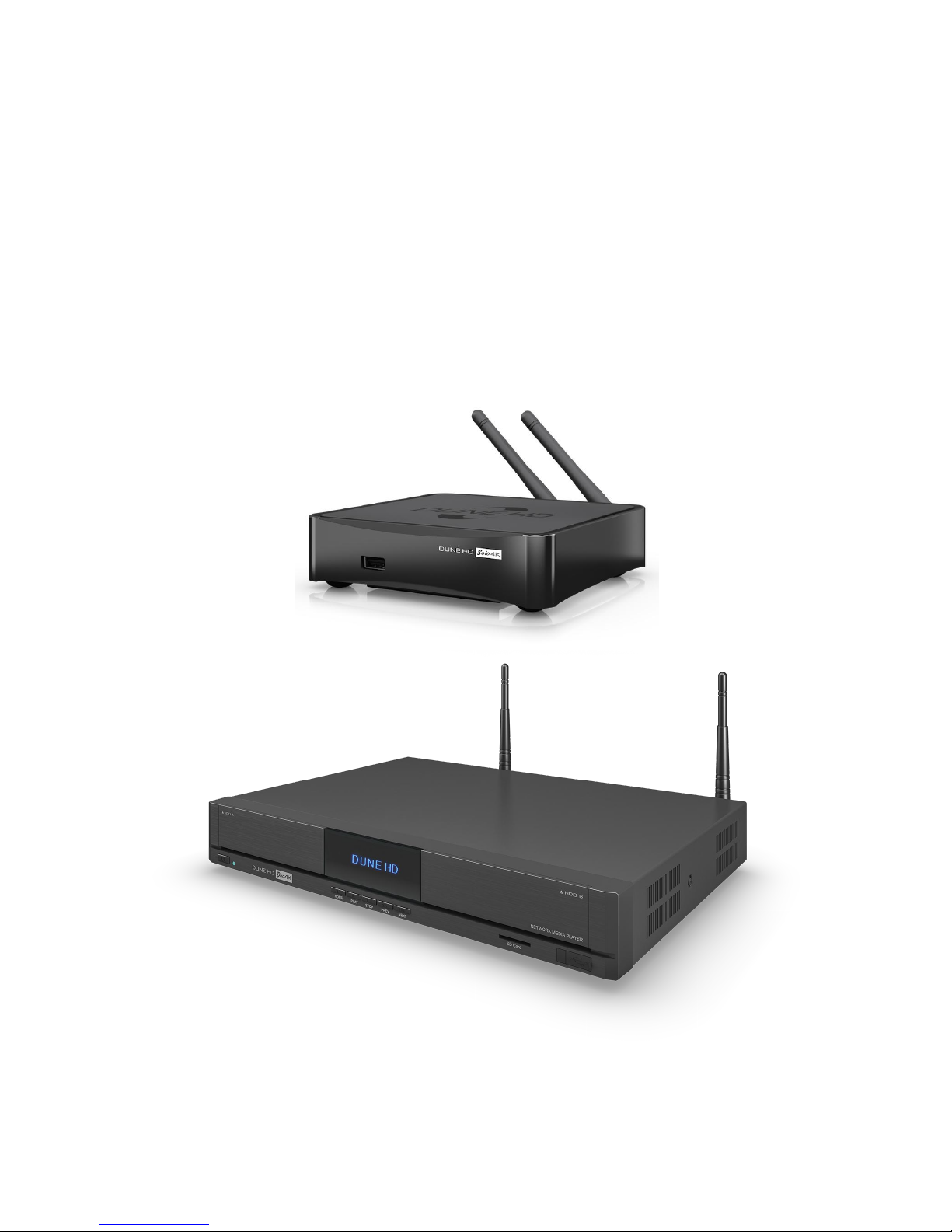
This document describes Z-Wave Smart Home controller functionality built-in into Dune HD Solo 4K and Dune HD Duo
4K media players.
The Z-Wave Smart Home controller allows management of Z-Wave network and Z-Wave devices in this network, and
additionally provides high-level Home Automation functionality (scripting etc).
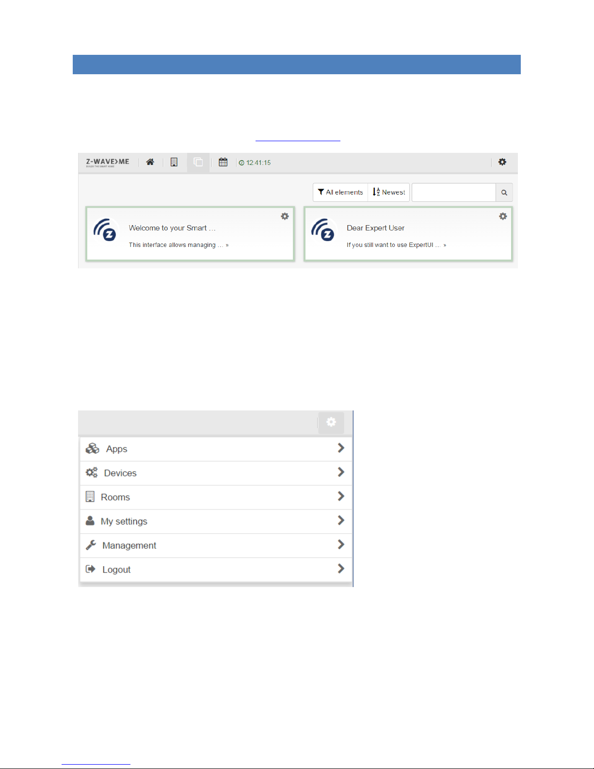
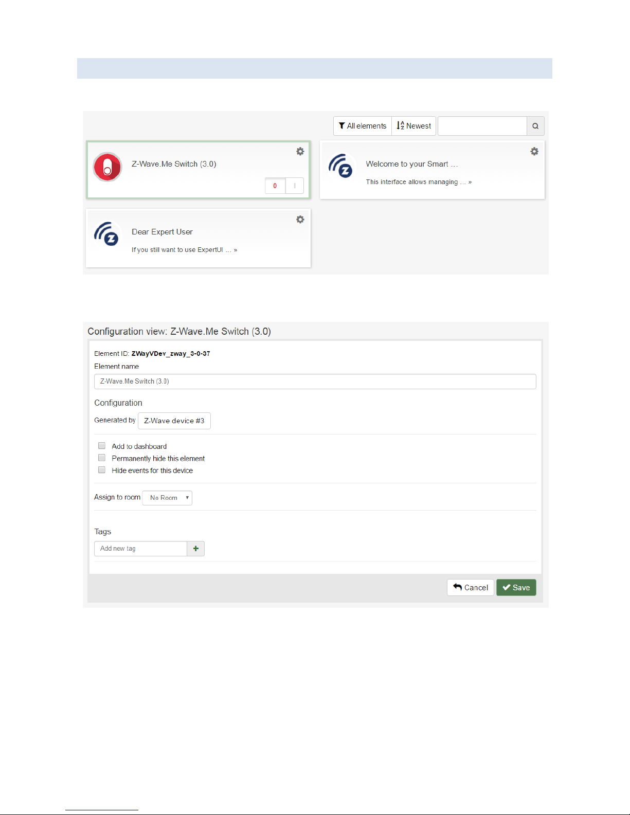
The Z-Wave Smart Home controller functionality can be accessed via the Web UI, which can be opened in a browser
on a PC, and also via iOS and Android applications. For custom integrations, HTTP / JavaScript API is available.
The Z-Wave Smart Home controller is based on Z-Way software stack from Z-Wave.Me. For more information about Z-
Way software stack and its features, please see:
Z-Wave.Me web site: http://www.z-wave.me
Z-Wave.Me forum: https://forum.z-wave.me
Z-Way product page: http://www.z-wave.me/index.php?id=22
Please check the following page for updates and additional information about Z-Wave support in Dune HD products:
http://dune-hd.com/support/z-wave
Z-WAVE PRODUCT I N FORMATION
This device is a Z-Wave static controller.
As a certified Z-Wave Plus device it can communicate with all other Z-Wave certified devices regardless of vendor or
year of origin and it implements the enhanced functions of Z-Wave Plus.
This device can communicate in a secure environment if the other device supports the secure environment too. If not
the controller will fall back to the normal communication mode automatically. During inclusion the use of secure
environment can be suppressed for performance reason if desired.
In Z-Wave all non-battery powered device will act as routers for other devices to form a so-called meshed network.
In case there is more than one controller in the network the controllers need to be kept synchronous in regard to their
knowledge of the network. This is called Controller Replication and the following policy applies: (a) in case there is a
SIS in the network every other controllers will query the SIS for updates; (b) In the rare case that there is no SIS and
this device is Primary Controller please re-include other controllers to perform a network information update.
The device supports the command classes ‘SwitchMultilevel’, ‘SwitchBinary’ and ‘Basic’ to catch events from devices
using these command classes to trigger actions in the controller. There is no other action performed than changing
values in the device data objects.
The device supports lifeline (association group 1, max 3 nodes) and 16 channels (simulating a generic Multilevel
Switch) to differentiate receiving commands from devices not able to send modern scene control commands. The
channels support the 3 same command classes (Basic, SwitchBinary, SwitchMultilevel and Scene Activation) that do
not perform any real action but allow command reception only.

3
GETTING STARTED
To start using Z-Wave Smart Home controller built-in in the Dune box, perform the following steps:
1. Ensure the following cables are connected to the Dune box:
a. Ethernet cable –to connect to the local Ethernet network. Wi-Fi connection can also be used, but
Ethernet connection is recommended for more stable operation.
b. A/V (e.g. HDMI) cable –to connect to a TV. If you want to use the Dune box just as a Z-Wave Smart
Home controller (w/o connection to a TV at all), this can be omitted.
2. Ensure the power cable is connected to the Dune box and ensure that the ON/OFF hardware switch at the
rear panel is in ON state.
3. Determine the IP address of the Dune box.
If the Dune box is configured to obtain IP address automatically via DHCP (which is the default
setting), you can determine the IP address via the Web UI of your home router.
If the Dune box is connected to a TV and the TV is switched on, you can see the IP address in “Setup
/ Information” menu on the TV.
4. Open the following URL in a web browser on PC:
http://IP-address:8083
NOTE: Some version of Internet Explorer web browser may not work. Latest versions of Chrome web
browser are well tested and recommended.
5. Log in as “admin” user. The Dune box may be preconfigured to expect one of the following initial passwords,
find the one which works on your box:
“admin”
“123456”
6. The system may ask you to change the password.
7. Finally, you will get into the Web UI of the Z-Wave Smart Home controller.
HOME A UTOMATION UI AND EXPERT UI
The Web UI of the Z-Wave Smart Home Controller has two parts: the Home Automation UI and the Expert UI.
When you log in into the Web UI, you get into the Home Automation UI.
The Home Automation UI:
Provides a subset of Z-Wave related functionality (most typically used functions).
Provides high-level Home Automation functionality (applications, rooms, scripting etc).
Is available via the following URL:
ohttp://IP-address:8083
The Expert UI:
Provides full access to low-level Z-Wave related functionality.
Is available via the following URL:
ohttp://IP-address:8083/expert
Can also be reached via the Home Automation UI in the following way:
oClick the “Settings” icon at the top right corner of the screen, choose “Devices” item, click “Manage
with Expert UI” button.

4
HOME AUTOMAT I ON UI
The Home Automation UI is intended for typical everyday Home Automation tasks, for high-level Smart Home
configuration, and provides only basic operations for Z-Wave network configuration and administration. For advanced
Z-Wave configuration, please use the Expert UI.
When you log in into the Web UI (using the URL http://IP-address:8083), you get into the Home Automation UI.
The top menu bar has the following icons:
“Home”: opens the Dashboard screen, which shows the UI elements (corresponding to Z-Wave devices and
other objects) configured to be shown on the dashboard for easy access.
“Rooms”: opens the Rooms screen, which shows the configured rooms.
“Elements”: opens the Elements screen, which shows all the available Elements (UI blocks corresponding to
configured Z-Wave devices and other objects).
“Events”: opens the Events screen, which shows the log of system events.
The “Settings” icon at the top right corner of the screen shows the “Settings” menu:
The “Settings” menu has the following items:
“Apps”: install and configure Home Automation applications.
“Devices”: configure Z-Wave devices and IP cameras.
“Rooms”: configure Rooms.
“My settings”: configure UI and account settings.
“Management”: system configuration.
“Logout”: log out from the Web UI.

5
HOME AUTOMATION UI: CONCEPTS AND FEATURES
The Home Automation UI uses the following concepts and provides the following features.
Z-WAVE DEVICE: HARDWARE Z-WAVE DEVICE INCLUDED INTO YOUR Z-WAVE NETWORK
You can add (include) and remove (exclude) Z-Wave Devices from your Z-Wave network controlled by the Z-
Wave Smart Home controller.
For each Z-Wave Device, the system may generate one or several Elements (UI blocks to work with some
aspect of the Z-Wave Device).
ELEMENT: A UI BLOCK TO WORK WITH SOME ASPECT OF A VIRTUAL OR PHYSICAL OBJECT
Elements are generated by the system automatically when you add Z-Wave devices or create instances of
Applications.
Each Z-Wave Device added to the system typically generates one or several Elements.
Many Applications typically create virtual objects and generate the corresponding Elements.
Elements are automatically deleted when the corresponding object which generated them is deleted.
You cannot manually delete Elements, but you can completely hide any Element if do not need it.
Elements can be added to Rooms and the Dashboard.
ROOM: A GROUP OF ELEMENTS
You can define as many Rooms as you need.
You can add/remove Elements to Rooms.
One Element may be added only to one Room.
There is one special Room called “No Room” which groups all Elements not added to any Room.
DASHB OARD: THE “HOME” SCREEN LISTING THE MOST IMPORTANT ELEMENTS
You can add/remove Elements to the Dashboard.
APPLICATION : A BUILDING BLOCK TO ADD LOGIC OR SPECIAL FEATURES
An Application is a ready-to-use script / template which can add extra logic and functionality to your Smart
Home setup, such as logic rules like “If-Then”, timers, interaction with external (non Z-Wave) systems, etc.
Some Applications are built-in into the system, and more can be installed from the App Store.
New Applications can be easily created by 3-parties: the Application is coded in JavaScript language using the
provided JavaScript API.
To use an Application, you create an instance of the Application, and configure the properties of this
Application instance (e.g. specify the Z-Wave devices to act on, specify the parameters, etc).
You can create many instance of the same Application.

6
HOME AUTOMATION UI: Z-WAVE DEVICES
To add a new Z-Wave device (include it into your Z-Wave network), choose “Devices” item in the “Settings” menu.
You will see the “Devices” screen:
Click "Add new" button in the "Z-Wave" section. You will see the following screen:
Click “Add new Z-Wave device and identify it automatically” button, or choose a brand/manufacturer of the Z-Wave
device from the list. You will see the “Include device” screen.
If the Z-Wave device is not in factory default state and was previously included into another Z-Wave network, first
perform the exclusion of the device from the old network:
Click “Exclusion again” link.
You will see “Ready to exclude” message.
Perform the “Exclude” action on the Z-Wave device (usually quickly press the button on the Z-Wave device 3
times; see the user manual of the Z-Wave device for device-specific information).
If the operation succeeds, you will see “Device excluded” message.

7
Perform the inclusion:
Click “Start inclusion” button.
You will see “Ready to include” message.
Perform the “Include” action on the Z-Wave device (usually quickly press the button on the Z-Wave device 3
times, see the user manual of the Z-Wave device for device-specific information).
If the operation succeeds, you will see “New device found” message, and the system will perform the
automatic configuration of the new device.
After you add a Z-Wave Device, you automatically get into the “Device” screen:
You can also open the “Device” screen in the following way: click “Manage” button in the “Devices” screen and click
the Z-Wave device.
On the “Device” screen, you see and can adjust the following configuration for the Z-Wave device:
Device name to be shown in the UI.
Elements corresponding to the Z-Wave device.
Hardware configuration of the Z-Wave device.
To remove a Z-Wave device (exclude it from your Z-Wave network), perform the following steps:
Choose "Devices" item in the “Settings” menu.
Click "Manage" button in the "Z-Wave” section.
Click "Remove" icon for the selected Z-Wave device.
Click "Start exclusion" button.
Perform the “Exclude” action on the Z-Wave device (usually quickly press the button on the Z-Wave device 3
times; see the user manual of the Z-Wave device for device-specific information).
If the operation succeeds, you will see “Device excluded” message.

8
HOME AUTOMATION UI: ELEMENTS
To see the list of all Elements, click “Elements” icon in the top menu bar. This will open the “Elements” screen:
To adjust Element configuration, click “Settings” icon at the top right corner of the UI block corresponding to the
Element. This will open the “Element Configuration” screen.
The “Element Configuration” screen shows the information about the Element and allows adjusting its configuration
(rename, hide, assign to Room, add to the Dashboard, etc).
To remove the unneeded Elements, either hide the Element via the “Element Configuration” screen (if the Element
supports hiding), or delete the object (Application instance of Z-Wave Device) which generated this Element.

9
HOME AUTOMATION UI: ROOMS
To see the list of all Rooms, click “Rooms” icon in the top menu bar. This will open the “Rooms” screen:
To view Elements in the Room, click the Room.
To create a new Room, click “Add new room” or use the “Rooms Configuration” screen.
To open “Rooms Configuration” screen, choose “Rooms” in the “Settings” menu. This will show the following screen:
To adjust Room configuration, click the “Edit” icon.
To delete a Room, click the “Remove” icon.
To add/remove an Element to a Room, use the “Element Configuration” screen.
To hide the special “No Room” Room, just move all Elements from this Room to other Rooms.
HOME AUTOMATION UI: DASHBOARD
To view the Dashboard, click “Home” icon in the top menu bar. This will show the “Dashboard” screen:
To add/remove an Element to the Dashboard, use the “Element Configuration” screen.

10
HOME AUTOMATION UI: APPLICATIONS
To view the list of available Application, choose “Apps” item in the “Settings” menu.
The “Local Apps” tab shows the list of locally installed Applications.
The “Online Apps” tab shows the list of Applications available via the App Store.
When viewing the list of available Applications, change the filter “Features apps” to “All apps” to see the list of all
available Applications.
Click “Add App” button to create an instance of an Application. This will create a new instance of the Application, and
you will see “Application Configuration” screen:
Enter the required parameters and click “Save”.
To see and manage the list of created Application instances, use the “Active” tab.

11
EXPERT UI
The Expert UI is intended for installers, technically savvy people and other users that know how to built and maintain
a Z-Wave based wireless network. Hence it uses some Z-Wave specific language and offers detailed insight into the
work and data structure if the Z-Wave network.
You can access the Expert UI in the following ways:
Open the following URL: http://IP-address:8083/expert
In the Home Automation UI, choose “Devices” item in the “Settings” menu and click “Manage with Expert UI”
button.
The Expert UI provides the following functions:
Add (include) and remove (exclude) Z-Wave devices to your Z-Wave network.
Configure Z-Wave devices.
Operate Z-Wave devices.
Manage Associations between Z-Wave devices.
Perform various operations on Z-Wave controller.
Access all data generated by the devices and perform all kind of functions and actions to the device.
Look behind the scene into the data structures, routing mechanisms and timings of the Z-Wave control stack.
This is particularly useful for debugging and software development.
The Expert UI does not provide any access to higher order business logic and automation. Please refer to the Home
Automation UI for these functions.
EXPERT UI: UI OVERVIEW
The Expert UI offers a home screen and four top menu items (tabs):
Control: Access to functions of the wireless devices included in the network.
Device: Access to information about devices.
Configuration: Configure the devices after inclusion if needed.
Network: Add and remove devices and manage the network.
The top menu bar also has a language selector. Please be aware that this selection is only valid for the Expert UI.
The timing info on the upper right side shows the time on the controller device. Its update serves as a heartbeat to the
system. All values shown in the UI are assigned to a time stamp indicating when the value of status information was
received from the wireless network. A red color of the time stamp indicates that and update request from the
controller for this value is pending.

12
EXPERT UI: HOME SCREEN
The Home screen offers some high level information about the software and a notepad where the user or installer can
leave important information for future use
The Network Information box offers some statistics about the number of devices in the network and how many of
them are mains or battery operated.
The Network Health box will list devices that have problems: the battery is down, the interview is not complete or the
device failed. Clicking on the statement will lead to a help page explaining the problems and giving guidance for
remediation.

13
EXPERT UI: CONTROL TAB
The Control Tab allows operating the various types of devices and shows the reported values in case of sensors or
meters. In case the control options offered here are not sufficient please refer to the Expert Command Tab as part of
the Configuration menu for a full set of functions supported by the device.
EXPERT UI: CONTROL TAB: SWITCH
The Switch screen lists all devices of the network supporting switching, dimmer or motor control capabilities. The
device name and Id and the current status of the switch is given and the time of the last status update. The “Update”
button forces an immediate update of the switch (if mains powered device). A ‘Switch All’ Icon shows whether or not
the specific device will react on a Switch All ON or Switch All Off command. A green triangle indicates that the device
will react to the command shown.
All actuators can be switched on or off. Dimmer and motors controls can be operated using a slider. For dimmer there
is a button “On” and “Full”. “Full” turns the dimmer always to 100 % diming value while “On” will turn to the last
dimming state before the dimmer was turned off. Clicking on the table heads reorders the table view of the data.

14
EXPERT UI: CONTROL TAB: SENSORS
The Sensor screen lists all devices of the network providing sensor information. Device name and id, the type of the
sensor, the actual sensor value and the sensor scale is listed. The Date/time column indicates when the given sensor
value was received. Its possible to call for a sensor update but bear in mind that battery operated device will only
respond after the next wakeup.
EXPERT UI: CONTROL TAB: METERS
The Meter screens lists all devices of the network providing (accumulating) meter information. Device name and id,
the type of the meter, the actual meter value and the meter scale is listed. The Date/time column indicates when the
given sensor value was received. Its possible to call for a meter update but bear in mind that battery operated device
will only respond after the next wakeup. Clicking on the table heads reorders the table view of the data.

15
EXPERT UI: CONTROL TAB: THERMOSTAT
The Thermostat screen lists all thermostat devices of the network. Device name and id and the current set point
temperature is shown. The Date/time column indicates when the given set point temperature was transferred to the
device. The set point temperature can be changed using the ‘+’ or ‘-‘ buttons or the slider. Clicking on the table heads
reorders the table view of the data.
Attention: The temperature value does not differentiate between heating and cooling devices. If a cooling and a
heating function shall have different set points please refer to the expert command section for more precise
command settings.
EXPERT UI: CONTROL TAB: LOCKS
The Lock screen lists all door lock devices of the network. Device name and id, the current status of the lock and last
time of the change of the status is listed.
Clicking on the table heads reorders the table view of the data.

16
EXPERT UI: DEVICE TAB
The Device Tab gives access to screens with more detailed information about the devices in the network and their
actual status.
EXPERT UI: DEVICE TAB: STATUS
The Status screen shows the actual network status of all devices. All devices are listed by their node id and name. The
date/time indicates the time of the last successful communications between the controller and this device (either
confirmed sending or reception). The green checkmark indicates that the device is alive. A red sign indicates that the
controller assumes the device not being active anymore. Mains powered devices can be checked for their network
availability by hitting the “Check connectivity” button.
In case the device interview and configuration was not performed properly a little question mark icon will indicate
this. Clicking on the question mark will open a window displaying the details of the interview process. The correct
loading of a Device Description File is indicated as well. For battery-operated device the time of the last wakeup, the
time of the next wakeup and the current wakeup status is shown. Clicking on the table heads reorders the table view
of the data. Clicking on the table heads reorders the table view of the data.

17
EXPERT UI: DEVICE TAB: BATTERY
The Battery screen gives an overview of the battery status of the battery-operated devices in the network. Devices are
listed by name and id. The last reported battery level (0…100 %) including update time is shown as well as the number
and type of battery if known. The “Update” button will request a status update from the device. The new status will
be available after the next wakeup of the device. Clicking on the table heads reorders the table view of the data.
EXPERT UI: DEVICE TAB: TYPE INFO
The Type info screen lists all devices of the network and indicates if they support enhanced Z-Wave functions such as
Security and Z-Wave Plus. Their Z-Wave protocol version, their application version and their device type indicator is
shown for information purposes too. Clicking on the table heads reorders the table view of the data.

18
EXPERT UI: DEVICE TAB: ACTIVE ASSOCIATIONS
The Active associations screen shows the current association set in the network. The lifelines (association to the
gateway to report status changes and heard beat) can be hidden if needed. A ‚Change’ button leads right to the
Configuration page of the device to change association settings.

19
EXPERT UI: CONFIGURATION TAB
The Configuration Tab allows configuring the functions of the device.
Pick the device to be configured from the drop down menu, then navigate between configuration screens using the
additional tabs.
EXPERT UI: CONFIGURATION TAB: INTERVIEW
The Interview screen the result of the device interview. In this process the controller tries to get information about the
device. In case the controller find a device description record for the device it will display further information about
the device that can not be obtained from the device itself. If the software will not automatically recognize the device
and load the description record a button “Choose Device Description Record” allows to do this manually.
The only configuration option on this tab is to change the given name of the device. During inclusion the software
generated a generic name but it is highly recommended to change this name. The given name should be descriptive
bit not too long.

20
The interview stage line gives information about the progress of the device interview by splitting it into the different
command classes supported by the device. ‘+’ indicate a successful interview, ‘0’ a permanent fail and a ‘.’ that this
command class is still in the waiting queue to be completed. There are a few reasons why an interview is not
complete: In most cases the devices went to deep sleep too early to has some problems. The button “Force Interview”
allows re-doing the whole interview. The button “Request NIF” requests a Node Information Frame from the device.
The Button “Show interview results” allows displaying the information about the different command classes found
during the interview. It is also possible to force the interview of a certain command class only.
This manual suits for next models
1
Other Dune HD Media Player manuals

Dune HD
Dune HD Smart H1 User manual

Dune HD
Dune HD Duo 4K User manual

Dune HD
Dune HD TV-301 User manual

Dune HD
Dune HD Base3D User manual

Dune HD
Dune HD TV-101 User manual

Dune HD
Dune HD Smart B1 User manual

Dune HD
Dune HD Smart BE User manual

Dune HD
Dune HD TV-204W User manual

Dune HD
Dune HD Smart B1 User manual

Dune HD
Dune HD Real Vision 4K Duo User manual