manuals.online logo
Brands
  1. Home
  2. •
  3. Brands
  4. •
  5. Dungs
  6. •
  7. Switch
  8. •
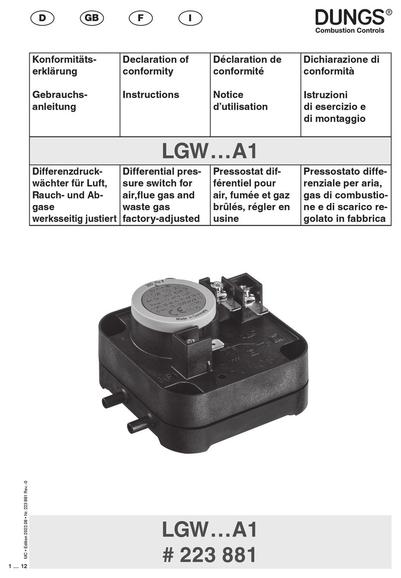
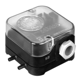
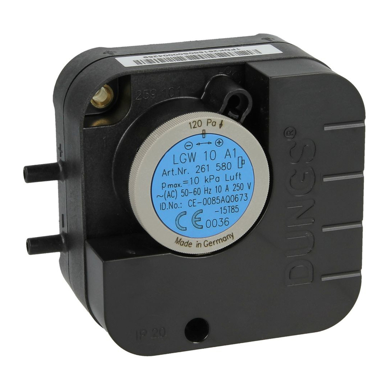
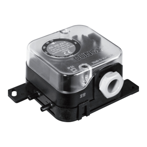
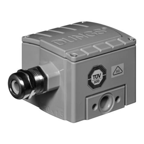
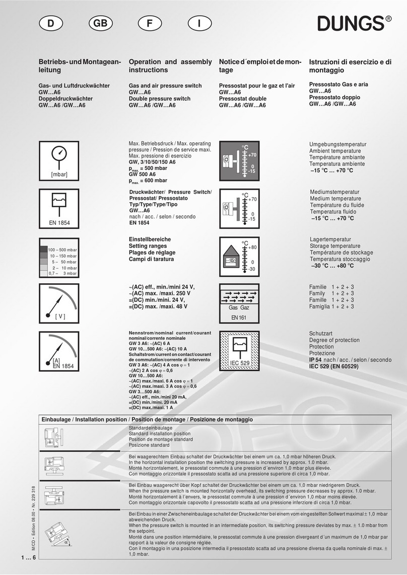
  9. Dungs LGW A2 Series Service manual

Dungs LGW A2 Series Service manual

1 … 6
M/CD • 08.00 • Nr. 223 869
Betriebs-undMontagean-
leitung
Luftdruckwächter
LGW…A2
Luftdruckwächter mit Prüftaste
LGW…A2P
Operation and assembly
instructions
Air pressure switch
LGW...A2
Airpressureswitchwithtestbut-
ton
LGW...A2P
Noticed'emploietdemon-
tage
Pressostat
LGW...A2
Pressostat avec touche de con-
trôle
LGW...A2P
Max. Betriebsdruck / Max. operating
pressure/ Pression de service maxi.
Max. pressione di esercizio
pmax. = 500 mbar (50 kPa)
Druckwächter/ Pressure Switch/
Pressostat/ Pressostato
Typ/Type/Type/Tipo
LGW…A2
LGW…A2P
nach / acc. / selon / a norme
DIN EN 1854
Umgebungstemperatur
Ambient temperature
Température ambiante
Temperatura ambiente
–15 °C … +70 °C
Mediumstemperatur
Medium temperature
Température du fluide
Temperatura fluido
–15 °C … +70 °C
Lagertemperatur
Storage temperature
Température de stockage
Temperatura stoccaggio
–30 °C … +80 °C
Luft- und Rauchgase
Air and flue gases
Air, fumée et gaz brûlés
Gas di combustione e aria
Schutzart / Degree of protection
Protection / Protezione
IP 54 nach / acc. / selon / a norme
IEC 529 (EN 60529)
Optional / Optional
en option / Optional IP 65
~(AC) eff., min./mini 10 V,
~(AC) max. /maxi. 250 V
=(DC) min./mini. 12 V,
=(DC) max. /maxi. 48 V
Einstellbereiche
Setting ranges
Plages de réglage
Campi di taratura
Standardeinbaulage
Standard installation position
Position de montage standard
Posizione standard
Bei waagerechtem Einbau schaltet der Druckwächter bei einem um ca. 0,5 mbar höheren Druck.
In the horizontal installation position the switching pressure is increased by approx. 0.5 mbar.
Monté horizontalement, le pressostat commute à une pression d´environ 0,5 mbar plus élevée.
Con montaggio orizzontale il pressostato scatta ad una pressione superiore di circa 0,5 mbar.
Bei Einbau waagerecht über Kopf schaltet der Druckwächter bei einem um ca. 0,5 mbar niedrigerem Druck.
When the pressure switch is mounted horizontally overhead, its switching pressure decreases by approx. 0.5 mbar.
Monté horizontalement à l´envers, le pressostat commute à une pression d´environ 0,5 mbar moins élevée.
Con montaggio orizzontale capovolto il pressostato scatta ad una pressione infeziore di circa 0,5 mbar.
BeiEinbauineinerZwischeneinbaulageschaltetderDruckwächterbeieinemvomeingestelltenSollwertmaximal±0,5mbar
abweichenden Druck.
When the pressure switch is mounted in an intermediate position, its switching pressure deviates by max. ±0.5 mbar from
the setpoint.
Monté dans une position intermédiaire, le pressostat commute à une pression d´un maximum de +/- 0,5 mbar par rapport
à la valeur de consigne réglée.
Con il montaggio in una posizione intermedia il pressostato scatta ad una pressione diversa da quella nominale di max. ±
0,5 mbar.
Einbaulage / Installation position / Position de montage / Posizione di montaggio
Istruzioni di esercizio e di
montaggio
Pressostati per aria
LGW...A2
Pressostati per aria con tasto di
prova
LGW...A2P
Nennstrom/nominal current/courant
nominal/corrente nominale ~(AC) 10 A
Schaltstrom/currentoncontact/courant
de commutation/corrente di intervento
~(AC) eff., min./mini 20 mA,
~(AC) max./maxi. 6 A cos ϕ = 1
~(AC) max./maxi. 3 A cos ϕ = 0,6
=(DC) min./mini. 20 mA
=(DC) max./maxi. 1 A
DI
GB F
αα
[mbar]
2,5 – 50 mbar
0,4 – 3 mbar
30 – 150 mbar
1 – 10 mbar
[ V ]
IEC 529IEC 529
➞ ➞ ➞ ➞
➞ ➞ ➞ ➞
➞➞ ➞➞
➞ ➞ ➞ ➞
➞ ➞ ➞ ➞
➞➞ ➞➞
°C
0
+80
-30
°C
0
+60
-15
°C
0
+60
-15
Ag
[A]
DIN 3398
EN 1854
DIN 3398 T2
M/CD • 08.00 • Nr. 223 869
2 … 6
G 1/4
7 Nm
1,2 Nm
+
1
2
Made in Germany
2
–
–
+
–
Made in Germany
–
+
2
3
1
2
Einbaumaße / Dimensions
Cotes d'encombrement / Dimensioni [mm]
LGW…A2
Einbaumaße / Dimensions
Cotes d'encombrement / Dimensioni [mm]
LGW…A2P
Druckanschluß
Pressure taps
Prises de pression
Manopola a pressione
Druckanschluß 1 (+)
AnschlußdeshöherenDruckes.
Druckanschluß 2 (–)
Anschlußdes niedrigerenDruk-
kes.
LGW…A2P: Auslieferung mit
Atmungsstopfen.Stopfenentfer-
nen bei (–) Anschluß.
Druckanschluß 3 (+)
Nur LGW…A2, optional
AnschlußdeshöherenDruckes.
Pressure connection 1(+)
Connects higher pressure.
Pressure connection 2(-)
Connects lower pressure.
LGW...A2:Deliverywithbreather
plug. Remove plug on (-)con-
nection.
Pressure connection 3(+)
Only LGW...A2, optional
Connects higher pressure
max. Drehmomente / Systemzubehör
max. torque / System accessories
max. couple / Accessoires du système
max. coppie / Accessorio di sistema
Geeignetes Werkzeug einsetzen!
Please use proper tools!
Utiliser des outils adaptés!
Impiegare gli attrezzi adeguati!
Drehmoment Haubenschraube
max. torque cap-head screw
Couple max. pour les vis du couvercle
Coppiadiserraggiomax.perviteacappuccio
M 4
2,5 Nm
G 1/8
5 Nm
G 1/8
A Ø 2,5 für Gerätestecker
DIN 43 650 A
B Längsschlitz 0,8 und
Kreuzschlitz DIN EN ISO
4757-Z2
1 Druckanschluß (+)
2 Druckanschluß (–)
3 nur LGW … A2 optional
Druckanschluß (+)
4 Prüftaste p+
A 2.5 dia. for connector socket
DIN 43 650 A
B Longitudinal slot 0.8 and
cross-head DIN EN ISO
4757-Z2
1 Pressure connection (+)
2 Pressure connection (-)
3 OnlyLGW...A2optionalpres-
sure connection (+)
4 Pressure button p+
A Ø 2,5 pour socle de connec-
teur DIN 43 650 A
B Empreinte longitudinale 0,8
et cruciforme DIN EN ISO
4757-Z2
1 Prise de pression (+)
2 Prise de pression (-)
3 uniquement LGW ... A2 en
option prise de pression (+)
4 Touche de contrôle p+
A Ø per spina apparecchio
DIN 43 650 A
B Taglio logitudinale 0,8 e
taglio a croce DIN EN ISO
4757-Z2
1 Attacco pressione (+)
2 Attacco pressione (-)
3 soloLGW...A2,arichiesta
attacco pressione (+)
4 Tasto di prova p+
Prise de pression 1 (+)
Raccordementdelapressionlaplusélevée.
Prise de pression 2 (-)
Raccordementdelapressionlaplusbasse.
LGW...A2P: Livrée avec un bou-
chon de mise à l'atmosphère (-).
Prise de pression 3 (+)
UniquementLGW...A2,enoption
Raccordementdelapressionlaplusélevée
Attacco di pressione 1 (+)
collegamentodellapressionepiùalta.
Attacco di pressione 2 (-)
Collegamentodellapressionepiùbassa.
LGW...A2P; fornitura con tappo di
deaearazione. Per effettuare il col-
legamento (-) togliere il tappo.
Attacco su presa 3 (+)
Solo LGW...A2, a richiesta
Collegamento della pressione più
alta.
Nr. No. 22
Nr. No. 14
21
23
Chrome Steel ✸Made in Germany
LGW … A2 LGW … A2P
R 1/4
[Nm]
18
19
Chrome Steel ✸Made in Germany
10
Made in Germany
1
2
20
15
82
82
B
PG11
Ø 4,6
24,9
45,5
6,9
8,8
10
18,5
18,5
A
Ø 2,5
Ø 4,6
3
Made in
Germany
53,7
53,7
72
LK Ø 76
LK Ø 78,8
Ø 4,2
15,2
15,2
44,6 Ø 3 x 8 tief
44,6
6,5
7
Made in Germany Made in
Germany
31,4
59
8
10
18,5
18,5
A
Ø 2,5
15
78,5
82
B
PG11
53,7
53,7
72
LK Ø 76
LK Ø 78,8
Ø 4,2
2
G 1/8
SW 14
4 p(+)
1 SW 22
G 1/4, konisch
87,5
Druckanschluß ø 4,6 nur als
Meßstutzen einsetzbar.
Druckanschluß nur über G1/4
möglich.
Ø 3 x 10 tief
3 … 6
M/CD • 08.00 • Nr. 223 869
[Nm] t ≤10 s
[Nm] t ≤10 s
22
Chrome Steel ✸Made in Germany
24
Einbau
LGW…A2P
1. DerDruckwächterwirddirektauf
einen Rohrstutzen mit R 1/4
Außengewinde aufgeschraubt.
Bild 1.
2. Nach Einbau Dichtheits- und
Funktionskontrolledurchführen.
AufvibrationsfreienEinbau
achten! Bild 2.
1
Installation of
LGW…A2P
1. Screw the pressure switch di-
rectly on a tube socket with R 1/
4 outer thread (see Fig. 1).
2. Afterinstallation,performaleak-
age and function test.
Ensure that the pressure
switch is installed free of
vibration (see Fig. 2).
Montage
LGW…A2P
1. Le pressostat peut se visser di-
rectementsurunpiquageR1/4"
Fig.1.
2. Après le montage contrôler la
jonction et l'étanchéité.
Veiller à ce que l'appareil
ne subisse pas de vibra-
tions ! Fig. 2.
Installazione
LGW…A2P
1. Il pressostato viene avvitato di-
rettamente su un tubo di soste-
gno con filetto esterno R 1/4
(Fig.1)
2. Dopo il montaggio effettuare i
controlli di tenuta e funzionalità.
Evitarepossibilitàdi vibra-
zioni! Fig 2.
2
Geeignetes
Dichtmittel
einsetzen!
Use proper seal-
ing compounds!
Utiliser une pâte à
joint adaptée!
Impiegaremateria-
le di tenuta ade-
guato!
Nr. No. 22
Nr. No. 14
Druckanschluß LGW…A2
Geeignete Schläuche (für Luft,
Rauch- und Abgase) einsetzen.
Schlauchinnendurchmesser A
max. 4 mm
SchlauchaußendurchmesserB
max. 15 mm
Schläuchegegenunbeabsichtig-
tes Abziehen sichern: Kabelbin-
der oder Schlauchschelle oder
Ω- Schelle.
LGW...A2 pressure connection
Usesuitablehoses(forair,flueand
exhaust gases)
Max.4mminnerhosediameter A
Max.15mmouter hosediameter B
Secure hoses to prevent
unintentional removal: use cable
tie or cable clip or Ωclip.
Prise de pression LGW...A2
Utiliser les tubes appropriés (pour
l’air, la fumée et les gaz brûlés).
Diamètre intérieur du tube A
max. 4 mm
Diamètre intérieur du tube B
max. 15 mm
Faire le nécessaire afin que les
tubesnepuissentpasêtreenlevés
par inadvertance: fixation par at-
tache - collier ou clips Ω.
Attacco di pressione LGW...A2
Peraria,gas di combustionee di
scarico, impiegare tubi flessibili
adeguati
Diametro interno del tubo A
max. 4 mm
Diametro esterno del tubo B
max. 15 mm
Assicurareitubicontroilpericolo
di distacco involontario serven-
dosi di serratubi, fascette per
tubi o fascette a forma di Ω.
Made in Germany
–
+
Made in Germany
–
+
A
B
DN
Rp
Mmax.
Tmax.
8
1/4
35
20
6
1/8
25
15
Tmax.
Mmax.
Mmax.
Gerät darf nicht als Hebel be-
nutzt werden
Do not use unit as lever.
Ne pas utiliser le pressostat
comme un levier.
L'apparecchio non deve
essere usato come leva.
M/CD • 08.00 • Nr. 223 869
4 … 6
1 NC
2 NO
3 COM
N
Prüf- taste
Electrical connection
IEC 730-1 (DIN EN 60 730 T1)
Via cable input PG 11, with rubber
grommet suitable for cables be-
tween 7 and 12.5 mm diameter.
Thereisno protec-
tion against acci-
dental contact.
Contact with live
parts is possible!
Toincreasetheswitchingcapacity,
we recommend that you use a RC
device for current values
<20mAand24Vd.c.applications.
Allacciamento elettrico
IEC 730-1 (DIN EN 60 730 T1)
Con passacavo PG 11, con scari-
co della trazione, collegato a mor-
setti a vite per cavi Ø 7 fino
Ø12,5 mm.
Non é sostanzial-
mente garantita la
protezione da sca-
riche, é possibile il
contatto con con-
duttoriditensione.
Peraumentarela potenza d'inseri-
mento con applicazioni DC < 20
mA e 24 V, consigliamo l'impiego
di un elemento RC.
Elektrischer Anschluß
IEC 730-1 (DIN EN 60 730 T1)
ÜberKabeleinführungPG11,mit
zugentlasung, an Schrauben-
klemmen für Kabel Ø7 bis
Ø12,5mm.Berührschutz ist
nicht grundsätz-
lich gewährlei-
stet, Kontakt mit
spannungsfüh-
renden Teilen
möglich!
Zur Erhöhung der Schaltleistung
wird bei DC-Anwendungen
<20mAund DC24VderEinsatz
eines RC-Gliedes empfohlen.
Raccordement électrique
IEC 730-1 (DIN EN 60 730 T1)
Raccordementsurbornieràvispar
PG11pourcâbledeØ7à12,5mm.
La protection
n'est pas garan-
tie, contact avec
des pièces sous
tensionpossible!
Pour augmenter la puissance de
rupture, l'utilisation d'un circuit
RCestpréconiséepourlesappli-
cations à courant continu< 20
mA et =(DC) 24 V.
Schaltfunktion
Bei steigendem Druck
1 NC öffnet
2 NO schließt
Bei fallendem Druck
1 NC schließt
2 NO öffnet
Switching function
While pressure is increasing
1 NC opens
2 NO closes
While pressure is decreasing
1 NC closes
2 NO opens
Schéma de fonctionnement
Pression montante
1 NC ouvre
2 NO ferme
Pression decendante
1 NC ferme
2 NO ouvre
Funzione di commutazione
Con pressione in salita
1 NC apre
2 NO chiude
Con pressione in discesa
1 NC chiude
2 NO apre
p
COM NO
NC
2
1
3
optional
optional
en option
opzione
DIN 43 650 A
PG 11
Prüftaste
nur LGW…A2P
Bei anstehendem Druck wech-
selt der Schalter durch Drücken
(Entlüften der unteren Kammer)
der Prüftaste p+ von NO nach
NC. Prüftaste ca. 5 s gedrückt
halten. Wird die Prüftaste freige-
gebenwechselt der Schaltervon
NC nach NO.
Touche de contrôle
uniquement LGW...A2P
Sous pression le switch commute
deNOversNClorsquel'onappuie
sur la touche de contrôle p+ (dé-
compression de la chambre infé-
rieure). Maintenir appuyée la tou-
che de contrôle pendant 5 s envi-
ron. Si l’on relâche la touche de
contrôle,lecommutateurpassede
NC à NO.
Tasto di prova
solo LGW...A2P
Premendo il tasto di prova p+
(deaerazione della camera infe-
riore), con presenza di pressio-
ne,l’interruttorecommuta da NO
a NC.Tenere premuto il tasto per
ca. 5 s. Lasciando libero il tasto
l’interruttore commuta da NC a
NO.
Prüf- taste Prüf- taste Prüf- taste
5 s
p
COM
NO
NC
2
1
3
p
COM NO
NC
2
1
3
p
COM
NO
NC
2
1
3
p+
Prüftaste
Test button
Touche de contrôle
Tasto di prova
NO NC
2 1
3
COM
N
optional
füroptischeSchaltanzeige(LED,
Glimmlampe)
Optional
for visual display (LED, filament
lamp)
en option
Contrôle de position (par LED
lampe fluorescente)
opzione
per visualizzazione di comando
ottica (LED, lampadina a baglio-
re)
Test button
only LGW...A2P
When pressure is present, the
switch changes from NO to NC
when test button p+ is pressed
(vents lower chamber). Press test
button for about 5 s. Whenthe test
button is released, the switch
changes from NC to NO.
5 … 6
M/CD • 08.00 • Nr. 223 869
Setting the pressure switch
Dismount the hood using a suita-
ble tool, e.g. screwdriver no. 3 or
PZ2, Fig. 1. Remove hood.
There is no protection
against accidental con-
tact. Contact with live parts is
possible.
Setting LGW…A2, LGW…A2P
Set the pressure switch at the set-
ting wheel ❚to the specified pres-
sure setpoint using the scale, Fig.
2.
Follow the instructions of the
burner manufacturer!
Pressureswitchswitchesaspres-
sureincreases:Set to left limitline
↑❚. Pressure switch switches as
pressurereduces:Settorightlimit
line ❚↓.
Remount hood!
Regolazione del ressostato
Smontarelacalottaconunattrezzo
adeguato, ossia cacciavite nr. 3 -
rispettiv, PZ 2, figura 1
Togliere la calotta.
Nonésostanzialmentega-
rantita la protezione da
scariche, é possibile il contatto
con conduttori di tensione.
Regolazione LGW…A2,
LGW…A2P
Tarare il pressostato, come in fi-
gura 2, sul valore di pressione
nominale prescritto, agendo sulla
rotella della scala graduata ❚.
Prestareattenzionealleprescri-
zioni del produttore del brucia-
tore!
Il pressostato scatta con pressio-
neinsalita:regolazionesullalinea
didelimitazionesinistra↑❚.Ilpres-
sostato scatta con pressione in
discesa:regolazionesullalineadi
delimitazione destra ❚↓. Rimonta-
re la calotta!
Einstellung des Druckwächters
Haube mit geeignetem Werkzeug
demontieren, Schraubendreher
No. 3 bzw. PZ 2, Bild 1.
Haube abnehmen.
Berührschutz ist nicht
grundsätzlich gewährt,
Kontakt mit spannungsführen-
den Teilen möglich.
Einstellung LGW…A2,
LGW…A2P
Druckwächter am Einstellrad mit
Skala ❚auf vorgeschriebenen
Drucksollwert einstellen, Bild 2.
Anleitung des Brennerherstel-
lers beachten!
Druckwächterschaltetbeisteigen-
dem Druck: Einstellung auf die
linke Begrenzungslinie↑❚.
Druckwächter schaltet bei fallen-
dem Druck: Einstellung auf die
rechte Begrenzungslinie ❚↓.
Haube wieder aufsetzen!
Réglage des pressostats
Enleverlesvisducapotenutilisant
un tournevis No3. PZ 2, Fig 1. En-
lever le capot.
Laprotectionn'estpasga-
rantie, contact avec des
pièces sous tension possible.
Réglage des LGW…A2,
LGW…A2P
Réglerlepressostatavecsonbou-
ton gradué ❚à la valeur désirée
Fig. 2.
Respecterlesrecommandations
du constructeur du brûleur!
Le pressostat commute par pres-
sion montante: régler sur la ligne
de limitation gauche ↑❚. Le pres-
sostatcommuteparpressiondes-
cendante: régler sur la ligne de
limitation droite ❚↓. Remonter le
capot!
1
2 LGW…A2 2 LGW…A2P
0,4
2,1
0,6
0,9
1,2
1,5
1,8
2,4
2,7
3
mbar
LGW 3 A2P
pmax. 500 mbar
~(AC) 10 A 250 V
CE-0085 AQ 0673
↑↓
0,4
2,1
0,6
0,9
1,2
1,5
1,8
2,4
2,7
3
mbar
LGW 3 A2
pmax. 500 mbar
~(AC) 10 A 250 V
CE-0085 AQ 0673
↑↓
Ersatzteile / Zubehör
Spare parts / Accessories
Pièces de rechange / access.
Parti di ricambio / Accessori
Set Haube, IP 54
Hood set, IP 54
Kit couvercle, IP 54
Set calotta, IP 54
Winkel-Einschraubstutzen
Angle union
Raccod coudé
Raccordo dol angolo filettato
G 1/8
Winkel-Einschraubstutzen
Angle union
Raccod coudé
Raccordo dol angolo filettato
G 1/4
Ersatzteile / Zubehör
Spare parts / Accessories
Pièces de rechange / access.
Parti di ricambio / Accessori
Nachrüstsatz Klima-Set
Climatic set, retrofit kit
Équipement complémentaire pour clima-set
Set aggiuntivo Klima-Set
Leitungsdose, grau
Line socket, grey
Prise, noire
Spina grigia, nera
GDMW, 3 pol. + E
Bestell-Nummer
Ordering No.
No. de commande
Codice articolo
214 828
210 318
Bestell-Nummer
Ordering No.
No. de commande
Codice articolo
230 276
230 278
230 279
Made in Germany
Made in Germany
M/CD • 08.00 • Nr. 223 869
6 … 6
Verwaltung und Betrieb
Head Offices and
Factory Usine et
Services Administratifs
Amministrazione e
Stabilimento
Korrespondenzanschrift
Postal address
Adresse postale
Indirizzare la corrispon-
denza a
Karl Dungs GmbH & Co.
Postfach 12 29
D-73602 Schorndorf
e-mail [email protected]
Internetwww.dungs.com
Rohrleitungsdichtheits-
prüfung: Kugelhahn
vor
demDruckwächterschlie-
ßen.
Nach Abschluß von Ar-
beiten am Druckwächter:
Dichtheitskontrolle und
Funktionskontrolledurch-
führen.
Niemals Arbeiten durch-
führen, wenn Spannung
anliegt. Offenes Feuer
vermeiden. Örtliche Vor-
schriften beachten.
Bei Nichtbeachtung der
Hinweise sind Personen-
oder Sachfolgeschäden
denkbar.
Pipelineleakagetest:clo-
se ball valve
upstream
of
the pressure switch.
On completion of work
on the pressure switch,
perform a leakage and
function test.
Never perform work if
power is applied. No na-
ked flame. Observe local
regulations.
If these instructions are
notheeded,theresultmay
bepersonalinjuryordam-
age to property.
Encas denon-respectde
ces instructions, des
dommages corporels ou
matériels sont possible.
Ne jamais effectuer des
travauxsoustension.Evi-
tertoute flammeouver-
te. Observer les régle-
mentations.
Unefoislestravauxsurle
pressostatterminés,pro-
céder toujours à un con-
trôle d´étanchéité et de
fonctionnement.
Contrôle de l´étanchéité
de la conduite: fermer le
robinet à boisseau sphé-
rique
avant
lepressostat.
Perlaprova ditenutadel-
letubature:chiudereilru-
binetto a sfera
davanti
al
pressostato.
Alterminedeilavorieffet-
tuati su un pressostato:
predisporre un controllo
sia della tenuta che del
funzionamento.
Innessuncaso sidebbono
effettuare lavori in presen-
zaditensioneelettrica.Evi-
tare i fuochi aperti e osser-
vare le prescrizioni di sicu-
rezza locali.
La non osservanza di
quanto suddetto può im-
plicare danni a persone o
cose.
Kondensat darf nicht in
dasGerätgelangenkann.
Bei Minustemperaturen,
durch Vereisung Fehl-
funktion/Ausfallmöglich.
Eviterl'entréedeconden-
sat dans le pressostat,
une prise en glace par
températurenégativenui-
raitàsonfonctionnement.
Do not allow condensate
toflowintotheequipment.
In case of sub-zero tem-
peratures, malfunction or
equipment failure may be
possible due to icing.
nell' apparecchio non
deveinfiltrarsialcunacon-
densa. Alle temperature
negative sarebbero pos-
sibilidisfunzioni dovutea
formazione di ghiaccio.
Arbeiten am Druckwäch-
ter dürfen nur von Fach-
personal durchgeführt
werden.
Seul du personnel spé-
cialisépeuteffectuerdes
travaux sur le pressos-
tat.
Work on the pressure
switch may only be per-
formedbyspecialiststaff.
Qualsiasi operazione
effettuatasul pressostato
deveesserefattadaparte
dipersonalecompetente.
Änderungen, die dem technischen Fortschritt dienen, vorbehalten / We reserve the right to make alterations in the course of technical improvement
Sous réserve de toute modification constituant un progrès technique / Ci riserviamo qualsiasi modifica tecnica e costruttiva
Karl Dungs GmbH & Co.
Siemensstraße 6-10
D-73660 Urbach
Telefon +49 (0)7181-804-0
Telefax +49 (0)7181-804-166
Safety
first
O.K.

Other manuals for LGW A2 Series

3

This manual suits for next models

1

Other Dungs Switch manuals

Dungs GW A4 Series User manual

Dungs

Dungs GW A4 Series User manual

Dungs GW A2 SGV Series Service manual

Dungs

Dungs GW A2 SGV Series Service manual

Dungs GW A6 Series Service manual

Dungs

Dungs GW A6 Series Service manual

Dungs LGW A2 Series User manual

Dungs

Dungs LGW A2 Series User manual

Dungs GW A4 Series User manual

Dungs

Dungs GW A4 Series User manual

Dungs LGW A2 Series Service manual

Dungs

Dungs LGW A2 Series Service manual

Dungs Klima-Set KS***A2-7 Series Service manual

Dungs

Dungs Klima-Set KS***A2-7 Series Service manual

Dungs GW A4 Series User manual

Dungs

Dungs GW A4 Series User manual

Dungs LGW A2 SGN Series User manual

Dungs

Dungs LGW A2 SGN Series User manual

Dungs LGW A1 Series Service manual

Dungs

Dungs LGW A1 Series Service manual

Dungs GW   500 A4/2 HP X Service manual

Dungs

Dungs GW 500 A4/2 HP X Service manual

Dungs GGW A4/2 X Series User manual

Dungs

Dungs GGW A4/2 X Series User manual

Dungs AA-A1-0 Series User manual

Dungs

Dungs AA-A1-0 Series User manual

Dungs GAO-A2 Series User manual

Dungs

Dungs GAO-A2 Series User manual

Dungs LGW A1 Series Service manual

Dungs

Dungs LGW A1 Series Service manual

Dungs KS A2-7 Series User manual

Dungs

Dungs KS A2-7 Series User manual

Dungs GW A4 HP SGS Series User manual

Dungs

Dungs GW A4 HP SGS Series User manual

Dungs LGW A4 Series Service manual

Dungs

Dungs LGW A4 Series Service manual

Dungs LGW A2 SGN Series User manual

Dungs

Dungs LGW A2 SGN Series User manual

Dungs GW A2 Series User manual

Dungs

Dungs GW A2 Series User manual

Dungs LGW A4 Series User manual

Dungs

Dungs LGW A4 Series User manual

Dungs GGW A4/2 X Series User manual

Dungs

Dungs GGW A4/2 X Series User manual

Dungs GGW A4-U/2 X Series Service manual

Dungs

Dungs GGW A4-U/2 X Series Service manual

Dungs GW A2 Series User manual

Dungs

Dungs GW A2 Series User manual

Popular Switch manuals by other brands

Enterasys Matrix 7H4385-49 Hardware installation guide

Enterasys

Enterasys Matrix 7H4385-49 Hardware installation guide

High Sec Labs SC21H-3 user manual

High Sec Labs

High Sec Labs SC21H-3 user manual

FOR-A HVS-390HS Operation manual

FOR-A

FOR-A HVS-390HS Operation manual

Siemens RUGGEDCOM RSG2488 installation guide

Siemens

Siemens RUGGEDCOM RSG2488 installation guide

Parker 6K Series User information

Parker

Parker 6K Series User information

Allied Telesis AT-9900 Series release note

Allied Telesis

Allied Telesis AT-9900 Series release note

Belkin OMNIVIEW P74696 user manual

Belkin

Belkin OMNIVIEW P74696 user manual

NETGEAR GSM7248 - ProSafe Switch user manual

NETGEAR

NETGEAR GSM7248 - ProSafe Switch user manual

Siemens SIRIUS 3SE6415-1 B0 Series Original operating instructions

Siemens

Siemens SIRIUS 3SE6415-1 B0 Series Original operating instructions

Conceptronic CBGIGA24 user manual

Conceptronic

Conceptronic CBGIGA24 user manual

HP 6125G Configuration guide

HP

HP 6125G Configuration guide

Eusso UKS8102-P Quick installation guide

Eusso

Eusso UKS8102-P Quick installation guide

Graco PROX17 Kit instructions

Graco

Graco PROX17 Kit instructions

Firmtech FB900AS user manual

Firmtech

Firmtech FB900AS user manual

StarTech.com HB20A7AME instruction manual

StarTech.com

StarTech.com HB20A7AME instruction manual

Linear Technology DC2019A Demo Manual

Linear Technology

Linear Technology DC2019A Demo Manual

HP 6127XLG Blade Series Command reference

HP

HP 6127XLG Blade Series Command reference

Xylem Rule 35A instruction manual

Xylem

Xylem Rule 35A instruction manual

manuals.online logo
manuals.online logoBrands
  • About & Mission
  • Contact us
  • Privacy Policy
  • Terms and Conditions

Copyright 2025 Manuals.Online. All Rights Reserved.