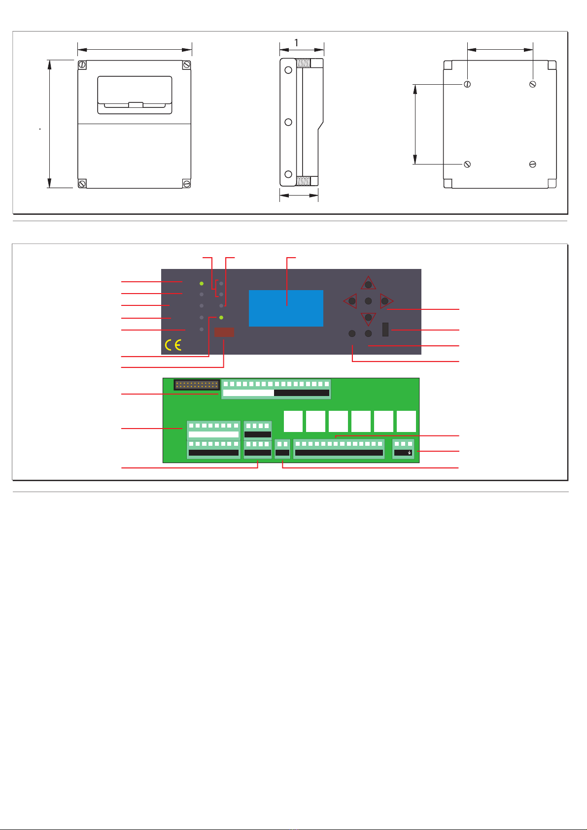
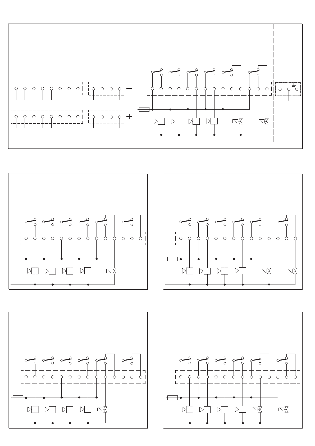
Electrical Installation
Initial Setup
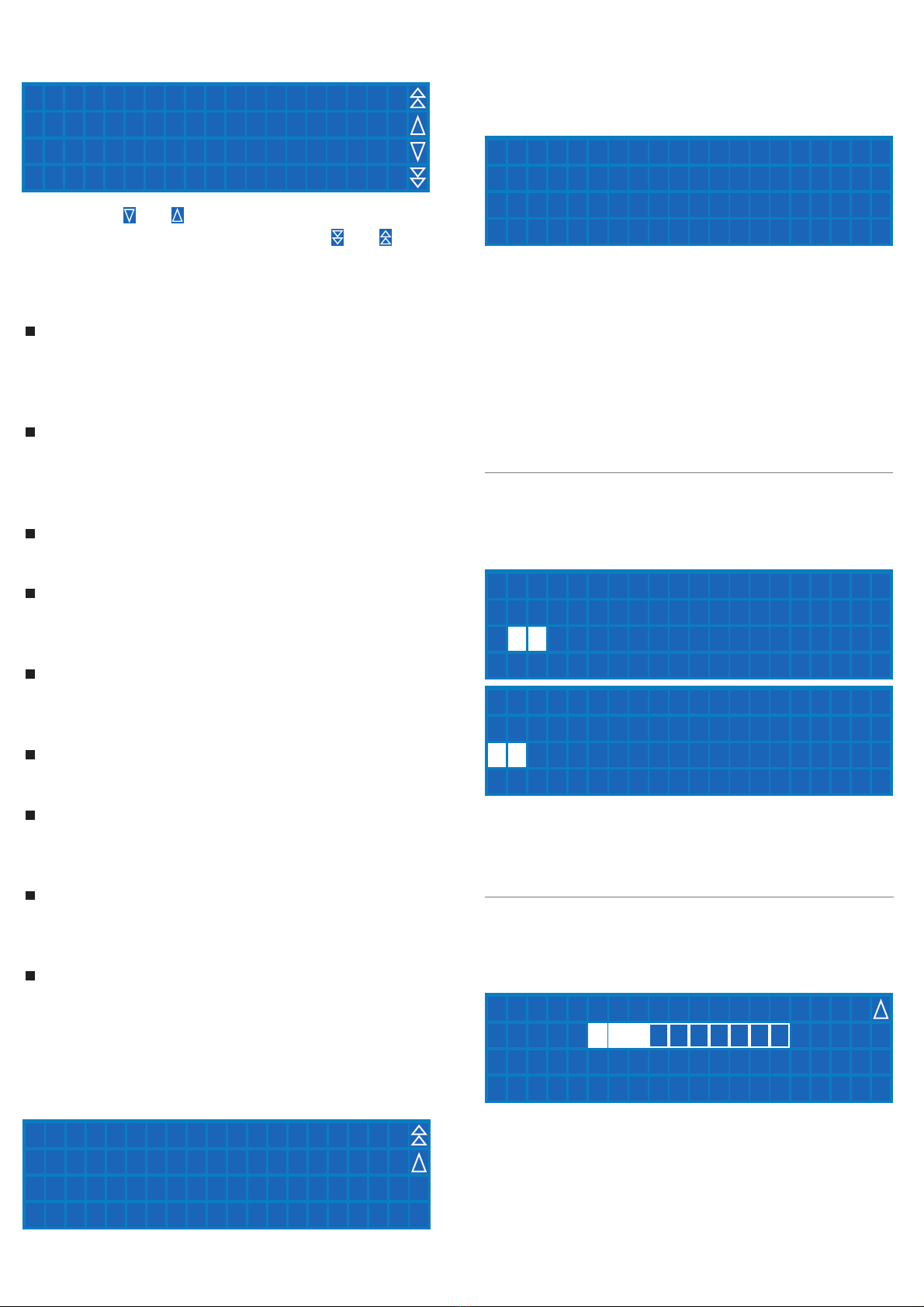
Powering Up
Installing A Sensor
The BX216 is a safety device designed to give audible
alarms and automatically provide latched electrical
isolation of associated gas safety shut off valves in the
event of a gas leak or build up of toxic gases. The sensor
can be located up to 100m from the gas detector. Cable
size should be 1mm2 CSA. If the sensor cables are run
seperately in specific conduit it is not essential to use
screened cable but if the cables are routed through
conduit or trunking containing other wiring the use of
screened cable is advisable. The wiring should be
performed by a qualified person in accordance with
current regulations. The terminal rails makes installation
easy and quick. Do not mount close to any heat source or
in an area where moisture is likely to effect operation.The
IP rating of this unit is IP65. Sensors should be positioned
as shown below. If you require any guidance on this
please call our technical help on 01905 797989. When the unit is first powered up you will see the above
screen as it counts down for 90 seconds during initial
warm up.
To set the BX216 up you will need to enter the menu
system. Press and hold Enter for 5 seconds and the screen
above will appear.The default password is "1234".Move
the cursor left and right using the keys, pressing enter to
select each number. When you have entered the correct
password the screens below appear.
Once completed, the unit is ready and shows the above
screen including; serial number, date and time, the
number of zones set, the current detected zone
(including the type of gas) and the current level of gas.
Each zone is displayed for 8 seconds in turn. To cycle
through the zones, use the left and right keys on the
keypad.To pause on a zone, press the Enter key. Press the
Enter again to move on and continue cycling through.
The sensors must be mounted as shown below with the
sintered head pointing vertically down. When replacing
sensors never seperate a sensing head from its PCB. The
sensor will have been calibrated using this particular
board and therefore will not function correctly with any
other.
Important Notes
Always check the wiring before powering up the
system.
Do not test this sensor with anything other than
Duomo test gas (see 'BX216 Operation' section for
further information). Concentrations above this will
damage the sensor and shorten sensor life. The
installation of this gas detector does not release the
user from observing all the regulations concerning the
characteristics, installation and and the use of gas
SGM595
autosetting
ON
SGM595
autosetting
ON
SGM595
autosetting
ON
300
1600
300
Natural Gas
Carbon
Monoxide
L.P.G
.
SN
Duomo
== BX216 ver. 1.2 ==
Countdown: 90
09:29
J00046
20/Sep/11
SN
Zone 2
Probe 01
000 ppm
__________
Toxic-09:29
J00046
20/Sep/11
Insert Password
0123456789
Insert Password
0123456789
****
Insert Password
0123456789
Password Accepted
the ventilation of the environment and the elimination of
combustion products in accordance with the local
recommendations, regulations and bylaws. For any
damage caused to people, property or animals resulting
from incorrect connection, installation or application of
this gas detector Duomo will not be held responsible or
liable.To ensure correct function after installation Duomo
provide a commissioning service using calibrated test
gases. For this service call 01905 797989.
w:
www.duomo.co.uk - e: [email protected].uk - t: 01905 797989 - f: 01905 774296 | ©Duomo (UK) Ltd. 2007