- 2 -
*FROM CENTER TO CENTER OF WALL BRACKETS
*NOTE: MEASURMENT IS APPROXIMATE ONLY, PLEASE
USE BAR AS TEMPLATE FOR ACTUAL CENTER TO
CENTER MEASUREMENTS.
USE
MOUNTING
PLATE
AS
TEMPLATE
*23-5/8"
(600 mm)
C/L
C/L
OPTIONAL
TO FINISHED
FLOOR
FINISHED
WALL LEVEL
2
34
1
12
9
11
10
6
8
7
3
4
2
6
5
5
C/L
M965507 Rev. 1.6 (5/17)
1
2
3
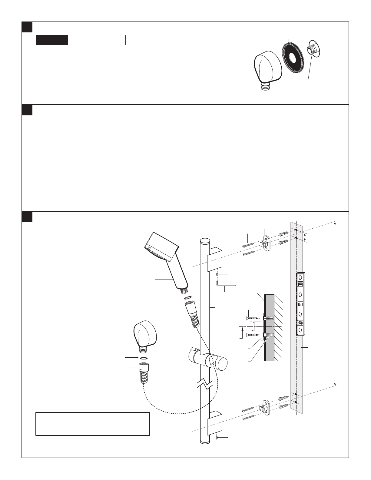
• Supply to WALL SUPPLY (1) is 1/2"NPT. See rough-in above for detailed information.
• Install RUBBER SEAL (2) onto WALL SUPPLY (1).
• Apply sealant or teon tape to threads of 1/2"NPT supply nipple. Thread
WALL SUPPLY (1) onto supply nipple making a water tight seal. WALL SUPPLY (1)
with RUBBER SEAL (2) should be tight against nished wall.
• The ADJUSTABLE SHOWER BAR (1) works best if secured to a wall stud or cross brace within the wall,
using the SCREWS (2) supplied.
• If the ADJUSTABLE SHOWER BAR (1) is to be installed on a tile or plaster wall the ANCHORS (4) and SCREWS (2)
should be used.
• Secure MOUNTING PLATES (3) to wall with SCREWS (2).
• For installations on drywall or tiled walls: Use ANCHORS (4) and SCREWS (2) for securing MOUNTING PLATE (3) to nished
wall. Drill two 1/4"dia. holes a minimum of 1-3/4" deep. Insert the two ANCHORS (4) ush with face of the nished wall.
• Determine desired height and location (optional) of the top MOUNTING PLATE (3). Using the TEMPLATE (12) supplied mark
the two spots for the ANCHORS (4). Use a level to make the center line between the two MOUNTING PLATES (3) vertical.
If the MOUNTING PLATES (3) are secured to a stud or cross brace drill small pilot holes for SCREWS (2).
• Install ADJUSTABLE SHOWER BAR (1)
onto installed MOUNTING PLATES (3).
Push ADJUSTABLE SHOWER BAR (1)
ush against nished wall and tighten
SET SCREWS (5) with HEX WRENCH (6)
supplied with accessory.
INSTALL WALL SUPPLY
INSTALL WALL BRACKETS
INSTALL ADJUSTABLE SHOWER BAR
CAUTION Turn off hot and cold water
supplies before beginning.
1/2" NPT
1


