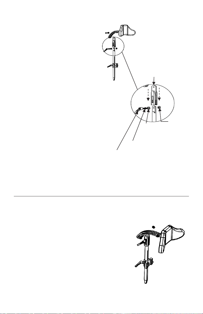
Last reinstall the head support arm over the flip
back post extension, securing in place with the
hardware that was set aside earlier in this step
(Figure 7).
Note: The additional Locking Handles Assembly that is
provided can be installed here instead of the original
hardware if easier readjustment is desired.
En dernier lieu, réinstallez le bras de support de la
tête sur l’extension rabattable, en l’immobilisant
avec le matériel qui a été mis de côté plus tôt dans
cette étape (Figure 7).
Remarque : L’ensemble de poignées de verrouillage
supplémentaires fourni peut être installé ici à la place
du matériel d’origine si un réajustement plus facile est
souhaité.
Last reinstall the head support arm over the flip back
post extension, securing in place with the hardware
that was set aside earlier in this step.
Note: The additional Latch Clamp Assembly that is provided
can be installed here instead of the original hardware if easier
readjustment is desired.
Flip Back Operation
Step 1 – Loosen Latch Clamp
To loosen, turn the latch clamp between ½ - 1 full turn
maximum. Raise the post extension as far as possible.
Note: Once the post extension has been raised, hold onto the
support arm and head pad to prevent it from falling forward.
Step 2 - Loosen Latch Clamp
The head pad can now be flipped back, away from
the user.
Note: Reverse the process to return the head support pad
to it’s original position. Tighten the latch clamp to prevent
any movement. The latch clamp can be repositioned on
the screw once it I tightened by pulling out and turning.
(FIGURE 7)
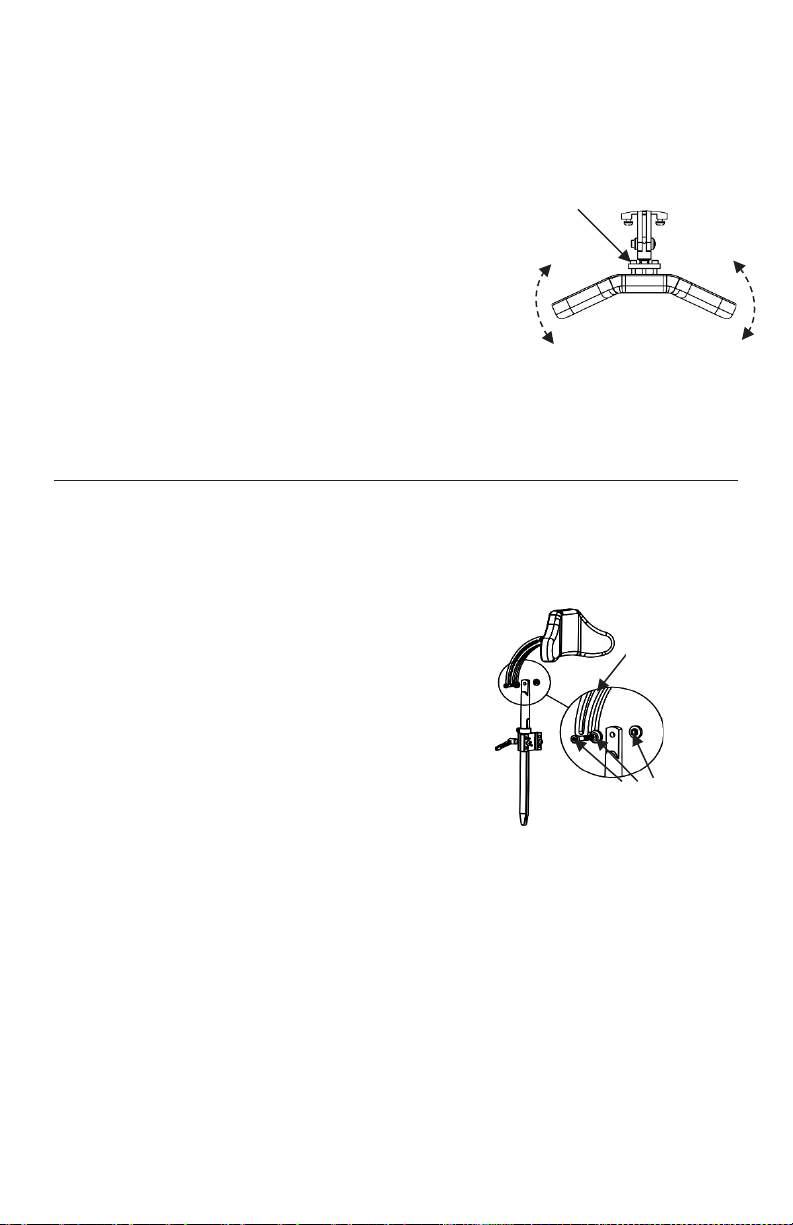
Next, install the flip back post
extension over the existing post.
With the hardware provided, secure
the flip back post extension by
inserting the locking handle through
the channel (with thin washer and
heavy duty washer) and tightening
the special nut on the other side
(Figure 6).
Note: both the heavy duty washer and
the special nut must be installed with the
small two sided protrusion going into the
elongated holes on each side of the flip back
post extension
Ensuite, installez l’extension de poste
rabattable sur le poste existant. Avec
le matériel fournit, fixez l’extension
de poste rabattable en insérant la
poignée de verrouillage dans le
canal (avec une rondelle fine et une
rondelle de haute résistance) et en
serrant l’écrou spécial de l’autre côté
(Figure 6).
Remarque : la rondelle résistante et l’écrou
spécial doivent être installés avec la petite
protubérance bilatérale dans les trous
allongés de chaque côté de l’extension
Next, slide the Head Support’s vertical post through the
mounting bracket and secure in place using the latch clamp
(see Figure 3). The channel in the vertical post should slide
over the Channel Screw (illustrated in Figure 2), ensuring
the post cannot rotate after installation.
Set the post to the desired height, and slide the locking
collar down to the top of the mounting kit. Secure in place
by tightening its screw against the head support vertical
post. This will ensure that the height of the head support
will always return to same height that it is set to.
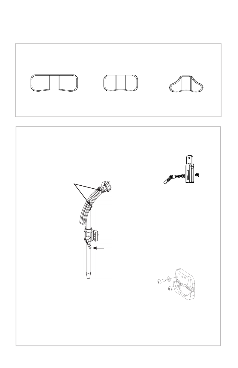
Step 3 – Head Pad
Unzip the back of the pad cover exposing the inside of the
pad. Set the ball on the head support into the received
inside the back of the pad. Secure using the 3 screws
provided (see Figure 4). The head pad can then be bent in
or out to customize the fit to the user’s head.
OPTIONAL STEP – Install Flip Back Hardware (if ordered)
To install the optional flip back hardware, first remove the
head support arm by unfastening the hardware (3 pieces)
that secures it (see Figure 5). Set the hardware and head
support arm aside to reattach after the flip back has been
installed.
Next, install the flip back post extension over
the existing post. With the hardware
provided with, secure the flip back extension
by inserting the latch clamp through the
channel (with thin washer and heavy duty
washer) and tightening the special nut on the
other side.
Note: both the heavy duty washer and the special
nut must be installed with the small two sided
protrusion going into the elongated holes on each
side of the flip back post extension
Screws used to secure
Pad to Head Support
Thin Washer
Heavy Duty Washer
Flip Back Post
Extension de poste
rabattable
(FIGURE 6)
Heavy Duty
Washer
Rondelle
robuste
Locking Handle
Poignée de
verrouillage
Thin Washer
Rondelle mince
Special Nut
Écrou spécial
Next, slide the Head Support’s vertical post through the
mounting bracket and secure in place using the latch clamp
(see Figure 3). The channel in the vertical post should slide
over the Channel Screw (illustrated in Figure 2), ensuring
the post cannot rotate after installation.
Set the post to the desired height, and slide the locking
collar down to the top of the mounting kit. Secure in place
by tightening its screw against the head support vertical
post. This will ensure that the height of the head support
will always return to same height that it is set to.
Step 3 – Head Pad
Unzip the back of the pad cover exposing the inside of the
pad. Set the ball on the head support into the received
inside the back of the pad. Secure using the 3 screws
provided (see Figure 4). The head pad can then be bent in
or out to customize the fit to the user’s head.
OPTIONAL STEP – Install Flip Back Hardware (if ordered)
To install the optional flip back hardware, first remove the
head support arm by unfastening the hardware (3 pieces)
that secures it (see Figure 5). Set the hardware and head
support arm aside to reattach after the flip back has been
installed.
Next, install the flip back post extension over
the existing post. With the hardware
provided with, secure the flip back extension
by inserting the latch clamp through the
channel (with thin washer and heavy duty
washer) and tightening the special nut on the
other side.
Note: both the heavy duty washer and the special
nut must be installed with the small two sided
protrusion going into the elongated holes on each
side of the flip back post extension
Screws used to secure
Pad to Head Support
Thin Washer
Heavy Duty Washer
5
5