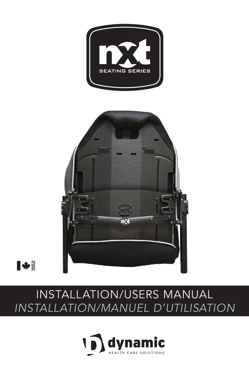
Dynamic NXT User manual

GEBRUIKERSHANDLEIDNG
INS TRUC TION MANUAL
NXTTM RUGLEUNINGEN
NXTTM BACK SUPPORTS

EC REP Advena Limited | Tower Business Centre, 2nd Flr., Tower Street Swatar, BKR 4013 Malta
1422791 Ontario Ltd
Dynamic Health Care Solutions
753011 Second Line EHS, Orangeville, ON L9W 5W4 Canada
+519-942-8441 | www.DynamicHCS.com
Voldoet aan:
- ISO 16840-4 Wheelchair Seating
-part 4: Seating Systems for use
in motor vehicles.
- RESNA WC-4:2012 Section 20:
Seating Systems for use in motor
vehicles.
Het wordt aangeraden om een
hoofdsteun te gebruiken wanneer de
rugleuning wordt gebruikt voor
transport in een motorvoertuig.
Complies with:
- ISO 16840-4 Wheelchair Seating -
part 4: Seating Systems for use in
motor vehicles.
- RESNA WC-4:2012 Section 20:
Seating Systems for use in motor
vehicles.
It is recommended that a headrest be
used when the back rest is used for
transport in a motor vehicle.
!
BELANGRIJK:
De installatie en instellingen moeten uitgevoerd
worden bij een gekwalificeerd persoon.
Het is belangrijk om de gebruikershandleiding te
raadplegen voor aanvullende informatie met
betrekking tot het veilig bedienen van de rolstoel.
IMPORTANT:
The installation and set up instructions should be
carried out by a qualified technician.
It is important to refer to the wheelchair owner’s
manual for additional safety information related
to the safe operation of the wheelchair.

3
INHOUDSOPGAVE TABLE OF CONTENTS
Bevestigingsmateriaal/Benodigde gereedschappen.......................... 4
Mounting Hardware/Tools Required
Belangrijke installatie informatie. ........................................4, 5, 6
Important Installation Information
Installatie instructies. ............................................. 7, 8, 9, 10, 11
Installation Instructions
De rugleuning uitnemen. .. . ................................................12
Removing the Backrest
De hoes verwijderen om te wassen..........................................12
Removing the Backrest Cover for Washing
Het aanbrengen van bekken/lumbaal of laterale steun...................... 13
Installing Pelvic/Lumbar or Lateral Supports
Het aanbrengen van de hardware voor hoofd/nek steun. .... ... ............ 13
Installing the Head/Neck Support Hardware
ArmadilloTM Rug/Back...............................................14, 15, 16
Garantie / Warranty. . ...................... .......... ....... ........... . . 17

4
BEVESTIGINGSMATERIAAL/BENODIGDE GEREEDSCHAPPEN
MOUNTING HARDWARE/TOOLS REQUIRED
BENODIGDE GEREEDSCHAPPEN / REQUIRED TOOLS
INBUSSLEUTEL / CLÉS ALLEN: 4mm & 5mm
3
10
4
9
11
5
6
7
8
2 121
NIB-1178 LINKER BUISKLEM
ACHTERAANZICHT
PART NO.
ITEM NO.
DESCRIPTION
QTY/CLAMP
NIB-1002
1
G3 CLAMP - INNER
1
NIB-1003
2
G3 CLAMP - OUTER
1
NIB-0999
3
G3 MOUNTING BRACKET-QR
1
NIB-1001
4
G3 CLAMP PLATE
1
NIB-0791
5
M6 FLAT WASHER
2
NIB-1069
6
M6X16mm HSCS-LOW PROFILE
2
NIB-0621
7
WASHER FOR ALUMINUM CLAMP
2
NIB-0813
8
M6X30mm HSCS-LOW PROFILE
2
NIB-1000
9
G3 MOUNTING PIN-LONG
1
NIB-1177
10
G3 MOUNTING PIN-SHORT
1
NIB-0787
11
M6X25mm HSCS-LOW PROFILE
2
NIB-1068
12
G3 CLAMP INNER NUT
1
NIB-1178 LEFT TUBE CLAMP
REAR VIEW
NIB-1004 RIGHT TUBE CLAMP
REAR VIEW
3
10
4
9
11
5
6
7
8
2 121
NIB-1178 LEFT TUBE CLAMP
REAR VIEW
NIB-1004 RIGHT TUBE CLAMP
REAR VIEW
PART NO.
ITEM NO.
DESCRIPTION
QTY/CLAMP
NIB-1002
1
G3 CLAMP - INNER
1
NIB-1003
2
G3 CLAMP - OUTER
1
NIB-0999
3
G3 MOUNTING BRACKET-QR
1
NIB-1001
4
G3 CLAMP PLATE
1
NIB-0791
5
M6 FLAT WASHER
2
NIB-1069
6
M6X16mm HSCS-LOW PROFILE
2
NIB-0621
7
WASHER FOR ALUMINUM CLAMP
2
NIB-0813
8
M6X30mm HSCS-LOW PROFILE
2
NIB-1000
9
G3 MOUNTING PIN-LONG
1
NIB-1177
10
G3 MOUNTING PIN-SHORT
1
NIB-0787
11
M6X25mm HSCS-LOW PROFILE
2
NIB-1068
12
G3 CLAMP INNER NUT
1
3
10
4
9
11
5
6
7
8
2 121
NIB-1178 LEFT TUBE CLAMP
REAR VIEW
NIB-1004 RECHTER BUISKLEM
ACHTERAANZICHT
SAME PARTS USED AS
NIB-1178 LEFT CLAMP
PART NO.
ITEM NO.
DESCRIPTION
QTY/CLAMP
NIB-1002
1
G3 CLAMP - INNER
1
NIB-1003
2
G3 CLAMP - OUTER
1
NIB-0999
3
G3 MOUNTING BRACKET-QR
1
NIB-1001
4
G3 CLAMP PLATE
1
NIB-0791
5
M6 FLAT WASHER
2
NIB-1069
6
M6X16mm HSCS-LOW PROFILE
2
NIB-0621
7
WASHER FOR ALUMINUM CLAMP
2
NIB-0813
8
M6X30mm HSCS-LOW PROFILE
2
NIB-1000
9
G3 MOUNTING PIN-LONG
1
NIB-1177
10
G3 MOUNTING PIN-SHORT
1
NIB-0787
11
M6X25mm HSCS-LOW PROFILE
2
NIB-1068
12
G3 CLAMP INNER NUT
1
ONDERDEEL
NR.
PART NO.
ITEM NR.
ITEM NO.
OMSCHRIJVING / DESCRIPTION
AANTAL/
KLEM
QTY/CLAMP
NIB-1002 1 G3 KLEM - BINNEN /G3 CLAMP - INNER 1
NIB-1003 2 G3 KLEM - BUITEN / G3 CLAMP - OUTER 1
NIB-0999 3 G3 MONTAGEPLAAT / G3 MOUNTING BRACKET-QR 1
NIB-1001 4 G3 KLEMPLAAT / G3 CLAMP PLATE 1
NIB-0791 5 M6 RING / M6 FLAT WASHER 2
NIB-1069 6 M6X16mm INBUSBOUT /M6X16mm SHCS BOLT 2
NIB-0621 7 RING VOOR ALUMINIUM KLEM / WASHER FOR ALUMINUM CLAMP 2
NIB-0813 8 M6X30mm INBUSBOUT / M6X30mm SHCS BOLT 2
NIB-1000 9 G3 MONTAGE PIN - LANG / G3 MOUNTING PIN-LONG 1
NIB-1177 10 G3 MONTAGE PIN - KORT / G3 MOUNTING PIN-SHORT 1
NIB-0787 11 M6X30mm INBUSBOUT / M6X25mm SHCS BOLT 2
NIB-1068 12 G3 BINNENMOER / G3 CLAMP INNER NUT 1
BELANGRIJKE INFORMATIE: LEES VÓÓR INSTALLATIE
IMPORTANT INFORMATION: READ BEFORE INSTALLATION
De Quickfit
bevestigingmaterialen zijn
geschikt voor verschillende
diameter rugbuizen.
3/4”/19mm, 7/8”/22mm en
1”/25mm rugbuizen passen
zonder inzetstukken
The Quickfit mounting hardware
can accommodate different size
back canes.
3/4”/19mm, 7/8”/22mm and
1”/25mm back canes can be
accommodated without inserts.
SAME PARTS USED AS
NIB-1178 LEFT CLAMP
DEZELFDE
ONDERDELEN ZIJN
GEBRUIKT ALS BIJ DE
LINKER KLEM NIB-1178

5
BELANGRIJKE INFORMATIE:
LEES VÓÓR INSTALLATIE
DRAAGVERMOGEN Het draagvermogen van de NXT rug is:
300lbs/136kg – 400lbs/182kg voor 22”/55cm.
23”/58cm – 29”/ 73cm is 550lbs/250kg met 4-punts bevestiging
LET OP: De Quickfit bevestigngsset van de NXT rugleuning is
voorgemonteerd met de bevestingspin op de achterste stand, om de
zitdiepte van de rolstoel te maximaliseren. Zie Fig.1 hieronder.
Door de bevestigingspin op de voorste stand te monteren, wordt de
zitdiepte verkleind. Zie Fig.2 hieronder.
Opmerking:De Quickfit bevestiging biedt een diepte instelling van 7.6
cm, voor en achter de rugbuizen.
De Quickfit bevestiging in de voorste positie plaatsen:
•Verwijder de buisklem van de montageplaat
•Draai de buisklem 180° bevestig het weer aan de montageplaat
•Plaats de klem zoals in Fig. 2
6"
3 7/8"
ACHTERZIJDE RUGBUIS
FIG. 2:
Pin positie voor de
kinderrugleuningen en de Armadillo
FIG. 1: Pin positie voor alle
rugleuningen behalve de
kinderrugleuning en de Armadillo
LET OP: De instellingen van de NXT rugleuning kunnen effect hebben
op de stabiliteit van de rolstoel.
Houd er rekening mee dat de positie van de rugleuning het zwaartepunt
kan verleggen. Als de rugleuning naar achteren gemonteerd is, komt het
zwaartepunt ook verder naar achteren te liggen. En als de rugleuning
naar voren gemonteerd is, komt het zwaartepunt verder naar voren te
liggen.

6
5
6"
3 7/8"
Please Note: Setting the desired position of the NXT back may
compromise the stability of the wheelchair.
Be aware that the forward and aft position for the backrest will change
the user’s centre of gravity within the wheelchair. A back set in the most
rearward position can significantly reduce the rearward stability of the
wheelchair. In contrast, a more forward back position may reduce the
wheelchair’s forward stability.
FIG. 1: PIN LOCATION FOR ALL BACKS
EXCEPT PEDIATRIC AND ARMADILLOILLO
FIG. 2: PIN LOCATION FOR PEDIATRIC
AND ARMADILLO BACKS
IMPORTANT INFORMATION:
FOLLOW BEFORE INSTALLATION
WEIGHT CAPACITY: The weight capacity of the NXT Back is
300lbs/136kg – 400lbs/182kg on 22”/55cm.
23”/58cm – 29”/ 73cm is 550lbs/250kg with 4 point hardware.
Please note that the Quickfit mounting hardware on the NXT Back are
pre-assembled with the cane clamp in the rear most mounting position
to maximize seat depth of the wheelchair. See Fig. 1 below.
The configuration can be changed by orienting the Quickfit cane clamp
forward, providing a forward mounting position. See Fig. 2 below.
Note:The Quickfit mounting hardware provides 3”/7.6cm of depth
adjustment, in front of and behind the back canes.
To set the Quickfit mounting hardware in the forward most position:
• Remove the cane clamp from the mounting plate
• Rotate the cane clamp 180° and re-attach it to the mounting plate
• Install clamp as shown in Fig. 2
BACK POST CENTRELINE

7
NXT RUGLEUNING MONTAGE INSTRUCTIES
NXT BACK INSTALLATION INSTRUCTIONS
1. Verwijder de rugleuning polstering
indien van toepassing
2. Bepaal de gewenste configuratie van
de montageplaat zoals beschreven op
pagina 5
3. Draai de 2 schroeven van de buisklem
los en bevestig de Quickfitklem aan de
rugbuizen
4. Plaats de buisklem op de gewenste
hoogte en draai de schroeven vast.
Volledig aandraaien wordt gedaan als
de rugleuning geïnstalleerd en
ingesteld is.
5. Meet de hoogte van de Quickfitklem
vanaf een vaste positie van de rolstoel
en bevestig de tweede klem op
dezelfde hoogte. Zorg er vervolgens
voor dat de montageplaten van de
Quickfit bevestiging parralel lopen aan
elkaar. Zie Fig. 4 hieronder.
6. De All Xtend™ Rugleuningen kunnen
traploos versteld worden van 40.6cm
tot 50.8cm en de Xtend™ Low van
33cm tot 43cm. Draai de 4
bolkopschroeven los met een 4mm
inbussleutel. Stel de rugleuning op de
gewenste hoogte in en draai de
schroeven weer vast. Als de Xtend™ in
de laagste positie is ingesteld, stop dan
de overtollige bekleding achter het
zitkussen. Zie Fig. 5 hieronder.
Remove wheelchair back upholstery if
applicable.
Establish the desired mounting plate
configuration for the user as described
on page 5.
Loosen the 2 tube clamp screws and
mount Quickfit bracket on the back
canes.
Position the cane clamp at the height
desired and tighten screws enough to
hold it in place. Full tightening can be
done when back is installed and final
adjustments have been done.
Measure the height of the Quickfit clamp
assembly from a fixed position on the
wheelchair and install the second at the
same desired height. Further, make sure
the cane clamp mounting plates are
mounted parallel with each other. See
Fig. 4 below.
All Xtend™ Backs can be infinitely
adjusted from 16”/40.6cm to 20”/50.8cm
or Xtend™ Low from 13”/33cm to
17”/43cm. Loosen the four cap screws
with a 4mm Allen wrench on the rear of
the backrest, set the backrest to the
desired height and tighten the lock nuts
into place. When the Xtend™ is in its
lowest position, tuck the excess padding
behind the seat cushion. See Fig. 5
below.
Fig. 4
De buisklemmen
moeten op dezelfde
hoogte en parallel
aan elkaar
gemonteerd worden.
Cane clamps must be
installed at the same
height and parallel to
each other
WAARSCHUWING: Gebruik
alleen de originele, bijgeleverde
bevestigingsset
WARNING: DO NOT substitute
hardware provided. Use only
high strength hardware
provided.
Fig. 5
Draai de 4
bolkopschroeven
los om de rughoogte
in te stellen.
Loosen 4 cap
screws to adjust
back heght.


8
STEP
ÉTAPE 1STEP
ÉTAPE 2
VERVOLG: NXT RUGLEUNING MONTAGE INSTRUCTIES
CONTINUED: NXT BACK INSTALLATION INSTRUCTIONS
7. Bevestig de rugleuning op de
montageplaten:
Stap 1:Haak de bovenste
haken over de bovenste
montagepinnen.
Stap 2: Beweeg de onderkant
naar achteren om de onderste
montagepinnen in de
vergrendeling te klikken.
Stap 3: Controleer of de
rugleuning vergrendeld is, door
de ontgrendleingshendel naar
beneden te drukken.
To install the backrest on the
mounting plates:
Step 1: Insert the top of the
backrest slot onto the top
adjustment pins
Step 2: Rotate the lower section of
the backrest rearward to lock it into
the locking latch to secure the
backrest in place.
Step 3: Ensure that the latches lock
completely by pushing down on the
release handle or latches if
necessary.

9
VERVOLG: NXT RUGLEUNING MONTAGE INSTRUCTIES
CONTINUED: NXT BACK INSTALLATION INSTRUCTIONS
MINIMUM WIDTH
MAXIMUM WIDTH
LOOSEN THESE SCREWS TO
ADJUST MOUNTING WIDTH
MINIMALE BREEDTE
MAXIMALE BREEDTE
MINIMUM WIDTH
8. Om de rugleuning goed te
bevestigingen kan het zijn dat de
breedte van de bevestigingsset
aangepast moet worden.
Stap 1: Draai de schroeven los
van de breedte instelling en de
ontgrendelingshendel.
Stap 2: Zorg dat de rugleuning
horizontaal en verticaal
gecentreerd is tussen de
rugbuizen en dat de onderste
vergrendeling binnen de
rugbuizen valt.
Stap 3: Draai vervolgens de
schroeven weer vast.
Stap 4: Door de breedte
instelling van de rugleuning past
het op 3 verschillende breedtes
rolstoelen. Een rugleuning van
40cm pas op een rolstoel van
40cm, 43cm en 45cm.
MAXIMUM WIDTH
To ensure the backrest is
properly fitted you may need to
adjust the mounting hardware to
match the back cane width.
Step 1: Loosen the screws to
adjust the mounting width and
the one-hand release.
Step 2: Make sure the backrest
is centered horizontally and
vertically between the back
canes and the locking latch on
the bottom is on the inside of
the post
Step 3: When satisfied, tighten
screws.
Step 4: The width adjustable
mounting hardware allows the
backrest to fit 3 sizes of
wheelchair, ie a 16”/40cm wide
back rest can fit a 16”/40cm, a
17”/43cm or 18”/45cm
wheelchair.
DRAAI DEZE SCHROEVEN LOS
OM DE BREEDTE IN TE STELLEN
LOOSEN THESE SCREWS TO
ADJUST MOUNTING WIDTH

10
VERVOLG: NXT RUGLEUNING MONTAGE INSTRUCTIES
OM DE ONTGRENDELING TE
VERGRENDELEN MOET HET
VOORSTE SCHROEFJE
VERPLAATST WORDEN NAAR
HET GAT ERACHTER. DE
SCHROEF ZORGT ERVOOR DAT
DE HENDEL NIET OMHOOG KAN.
OPMERKING: HET ACHTERSTE
GAT BEVAT GEEN
SCHROEFDRAAD, MAAR DE
SCHROEF MAAKT ZELF DRAAD
9. Zorg ervoor dat de algehele uitlijning en pasvorm correct is. Zo niet,
maak de aanpassingen zoals vereist.
10. Draai de schroeven van de bevestigingsset goed vast.
11. De diepte instellingen kunnen het best gedaan worden met de cliënt in
de rolstoel. Draai de schroeven op de montageplaat los en positioneer
de rugleuning zoals gewenst. Draai de schroeven vervolgens weer vast.
De rugleuning is asymmetrisch te monteren, maar zorg ervoor dat deze
indien gewenst symmetrisch gemonteerd wordt.
SCHROEVEN VOOR
BREEDTE INSTELLING
SCHROEVEN VOOR
DIEPTE EN HOEK
VERSTELLING
BUISKLEM
SCHROEVEN
DRAAI DEZE SCHROEVEN LOS
OM DE DIEPTE TE VERLENGEN
QUICK RELEASE BEVESTIGING
VERSTELLING VAN
DE LATERALE DIEPTE
VASTE BEVESTIGING
SCHROEVEN VOOR DIEPTE
EN HOEK VERSTELLING
GEBRUIK DEZE GATEN ALS
REFERENTIE VOOR DE
SYMMETRIE TUSSEN DE
LINKER- EN RECHTERKANT
BUISKLEM
SCHROEVEN
GEBRUIK DEZE
BEVESTIGINGSGATEN VOOR
EEN ARMADILLO EN EEN
KINDERRUG

11
CONTINUED: NXT BACK INSTALLATION INSTRUCTIONS
9
9. Make sure that the overall fit and alignment of the back is correct, if not
make adjustments as required.
10. Secure the cane clamp screws onto each back cane.
11. Setting the depth and recline settings it is best done with the client
seated in the wheelchair. While the client is seated and supported in
the wheelchair, loosen the depth screws on the mounting plate and
set to the desired position. Tighten all screws to lock the backrest in
position. The backrest can be mounted asymmetrically, so be sure that
it is symmetrical if desired.
10
TO LOCK LATCH MOVE THIS
SCREW TO THE ADJACENT
HOLE, THIS WILL PREVENT
THE LATCH FROM LIFTING.
REPLACE SCREW FOR
NORMAL OPERATION.
NOTE: EXTRA HOLE IS NOT
THREADED BUT THE SCREW
WILL MAKE ITS OWN THREAD.
WIDTH
ADJUSTMENT
SCREWS
TUBE
CLAMPING
SCREWS
LOOSEN THESE SCREWS
TO EXTEND LATERAL
QUICK RELEASE MOUNT
LATERAL CONTOUR
DEPTH ADJUSTMENT
FIXED MOUNT
DEPTH/RECLINE
ADJUSTMENT SCREWS.
USE THESE HOLES IN THE PLATE
AS A REFERENCE GUIDE FOR
SYMMETRICAL ADJUSTMENT ON
THE LEFT AND RIGHT SIDES.
TUBE CLAMPING
SCREWS.
MOUNT PINS IN THESE HOLES
FOR PEDIATRIC AND
ARMADILLO BACKS.

12
DE RUGLEUNING UITNEMEN REMOVING THE BACKREST
DE HOES VERWIJDEREN OM TE WASSEN
REMOVING THE COVER FOR WASHING
Maak het klittenband los
en verwijder het
schuimkussen voordat u
de buitenhoes wast.
Undo velcro closure &
remove foam pad before
washing outer cover
De rugleuning uitnemen
Stap 1: Til de vergrendelingshendel met één hand omhoog om de
rugleuning te ontgrendelen en duw de onderkant naar voren.
Stap 2: Til de rugleuning van de bovenste montagepinnen om het uit te
nemen.
To remove the backrest from the wheelchair
Step 1: Lift on the one hand release lever to release the latches, push the
bottom of the back forward.
Step 2: Lift the backrest off the upper pins to remove completely.
1. Verwijder de hoes van de rugleuning.
2. Voor lichte reiniging kan de hoes afgenomen worden met een vochtige doek.
3. Volg de wasinstructies die bij de hoes bijgeleverd zijn.
1. Remove the upholstery from the backrest.
2. For light cleaning of the backrest fabric may be wiped down with a damp
cloth.
3. Follow laundering instructions provided with the cover.

13
1. Remove the upholstery from the backrest.
2. For light cleaning of the backrest fabric may be wiped down with a damp cloth.
3. Follow laundering instructions provided with the cover.
1. Retirez le rembourrage du dossier.
2. Pour nettoyer légèrement le tissu du dossier, essuyez-le avec un chiffon humide.
3. Suivez les instructions de lavage fournies avec la couverture.
INSTALLING HEAD/NECK SUPPORTS
INSTALLATION DE SUPPORTS DE TÊTE/COU
Montagepunten voor de NXT Multifit
hoofdsteun of after market hoofd- en
neksteunen, zijn al voorbereidt in de
schaal van de rugleuning
Attachment slots are stamped into the
back shell for attaching the NXT Multifit
Head Support or after market head/
neck supports.
BEKKEN/LUMBAAL STEUNEN &
OPTIONELE LATERALE STEUNEN
PELVIC/LUMBAR SUPPORTS &
OPTIONAL LATERAL SUPPORTS
Montagepunten voor hoofd/neksteun
Pre stamped head/neck rest slots
Bekken/lumbaal steun
Pelvic-lumbar support pads
Laterale steun
Lateral support pads
1. De bekken/lumbaal steun kan uniek worden
gepositioneerd voor een optimale bekken
positionering en lumbale ondersteuning. De
steunen worden los bijgeleverd zodat ze
tijdens het monteren van de rugleuning per
persoon kunnen worden aangepast. Plaatst
de steun tussen de binnenzijde van de
schaal en de hoes. (zie onderstaande
afbeelding) Plak het klittenband aan de
voorzijde van de steun vast aan de hoes.
2. Indien nodig zijn er ook laterale steunen
beschikbaar. Plaats deze net als de
lumbaalsteun tussen de schaal en de hoes.
3. Plaats de bekleding weer in de schaal en
maak de klittenbandsluitingen dicht.
The Pelvic-lumbar support pads can be
uniquely positioned to provide optimal
pelvic positioning and lumbar support. The
supports come uninstalled, allowing them to
be specifically fit to the person at the time
of the back installation. Fit as shown
between fabric and inner shell of backrest.
Hook Velcro on the front of the pelvic pad
attached to the Velcro compatible fabric of
the cover.
Where additional lateral support is required,
optional lateral supports are. Fit pads
between the fabric and the shell of the
backrest.
After positioning support pads, seal velcro
closure, reposition cover on the backrest
shell, attach the upholstery.

14
ArmadilloTM RUGLEUNING ArmadilloTM BACK
1. Hoogte en hoek instellingen
De bevestiging van de Armadillo
rugleuning worden op dezelfde
manier gedaan als de andere NXT
rugleuningen, dus door de
universele rugbuisklemmen. De
rughoogte en de hoek van de schaal
zijn in te stellen met de klemmen
zoals terug te vinden is in NXT
MONTAGE INSTRUCTIES/
GEBRUIKERS HANDLEIDING.
OPMERKING: Zorg ervoor dat bij
het bevestigen van de rugleuning,
de vergendeling op de onderste
pinnen is gesloten.
2. De rugleuning aanpassen naar de
zitbreedte van de rolstoel.
De Armadillo rugleuning is
beschikbaar voor stoelen van 35cm
tot 60cm. Draai schroeven A en B
los om de breedte van de
montagehaken aan te passen.
Schuif de haken op de juiste breedte
en draai de schroeven vast. Schroef
A draait vast in schroefdraad en
schroef B wordt vastgezet d.m.v.
een schuifmoer die ook de bovenste
delen op hun plaats houdt. De
breedte is traploos instelbaar en de
haken kunnen zowel symmetrisch al
asymmetrisch op de rug bevestigd
worden.
Setting Back Height and Angle
The Armadillo back installs, like all
NXT backs, using Universal Clamps
attached to the back canes. The back
height and angle of the middle shell
segment are adjusted using these
clamps as shown in the NXT
INSTALLATION/USERS MANUAL.
NOTE: When installing a back, always
ensure the latches are closed (down)
on the lower pins.
Adjusting Back to match Chair
Width
The Armadillo back is available in
sizes to fit chair widths 14”-24”. To
adjust the mounting hook width,
loosen screws A and B and slide the
mounting hooks to the correct width
and tighten all screws. Screw A fits
into a fixed threaded hole in the
middle shell segment and screws B fit
into sliding nuts which also hold the
upper aterals in place if installed. The
hooks are infinitely adjustable
between the minimum and maximum
width and are normally placed
symmetrically on the back but may be
asymmetrical if required.
A
B
NOTE:
Screws A & B on the left and right side of the back must
be used to make width adjustments.
NXT Seating - MAPS Back
Multi Adjustable Postural Support
2. Adjusting Back to match Chair Width
The MAPS back is available in sizes to fit chair widths 14”-24”. To adjust the mounng
hook width, loosen screws A and B and slide the mounng hooks to the correct width and
ghten all screws. Screw A fits into a fixed threaded hole in the middle shell segment and
screws B fit into sliding nuts which also hold the upper laterals in place if installed.
The hooks are infinitely adjustable between the minimum and maximum width and are
normally placed symmetrically on the back but may be asymmetrical if required.
1. Setting Back Height and Angle
The MAPS back installs, like all nxt backs, using Universal Clamps aached to the back canes.
The back height and angle of the middle shell segment are adjusted using these clamps as
shown in the nxt INSTALLATION/USERS MANUAL.
NOTE:
When installing a back, always
ensure the latches are closed (down) on the lower pins.
CENTRAL
CHANNEL
MONTAGEHAAK
MOUNTING HOOK
MIDDEN SEGMENT
MIDDLE SEGMENT
OPMERKING: Schroef
A&B aan de linker- en
rechterkant moeten
gebruikt worden om de
breedte aan te passen.
NOTE: Screws A & B on
the left and right side of
the back must be used to
make width adjustments.
RUGGENGRAAT
UITSPARING

15
3. Hoofdsteun bevestiging Head Rest Mounting
The Upper and Middle segments of
the Armadillo shell have slots to
accept mounting hardware for the
NXT MultiFit Head Rest. Choose the
location which provided the best
positioning for the head rest
4.
CANAL
CENTRAL
B B
EE
BOVENSTE
LATERAAL
ONDERSTE LATERAAL
MET GROTE PAD
3. Head Rest Mounting
The Upper and Middle segments of the MAPS shell have slots to accept mounng hardware
20°
40°
30°
30°
UPPER SEGMENT
LOWER SEGMENT
G
F
HINGE JOINT
HINGE JOINT
4. Lateral Installation and Adjustment
Upper laterals are held in place by screws B and the Lower laterals by screws E. These
screws thread into sliding nuts in slots on the laterals allowing the laterals to be infinitely
adjustable between their most inner and outer posions only limited by the postural
requirements of the occupant of the wheelchair and any structural components of the
wheelchair. Loosening screws B or E allowing the laterals to slide will not affect the
posioning of the mounng hooks.
5. Angle Adjustments
The Upper and Lower segments of the MAPS
shell are individually angle adjustable with
respect to the Middle segment. Loosening
screws G (on both sides of hinge joint) allows
the Upper segment to be lted forward up to
40 degrees or backward up to 20 degrees.
Loosening screws F (on both sides of hinge
joint) allows the Lower segment to be lted
forward or backward up to 30 degrees.
Tightening the screws locks the segment
prevenng a change in angle. Ensure all 8
screws are ghtened.
LOWER LATERAL
WITH LARGE PAD LOWER LATERAL
WITH LARGE PAD
B B
EE
UPPER
LATERAL
UPPER
LATERAL
LOWER LATERAL
WITH LARGE PAD
LOWER LATERAL
WITH LARGE PAD
3. Head Rest Mounting
The Upper and Middle segments of the MAPS shell have slots to accept mounng hardware
for the nxt MulFit Head Rest. Choose the locaon which provided the best posioning for
the head rest.
VOORAANZICHT
FRONT VIEW
20°
40°
30°
30°
UPPER SEGMENT
LOWER SEGMENT
G
F
HINGE JOINT
HINGE JOINT
4.
Upper laterals are held in place by screws B and the Lower laterals by screws E. These
screws thread into sliding nuts in slots on the laterals allowing the laterals to be infinitely
adjustable between their most inner and outer posions only limited by the postural
requirements of the occupant of the wheelchair and any structural components of the
wheelchair. Loosening screws B or E allowing the laterals to slide will not affect the
posioning of the mounng hooks.
5. Angle Adjustments
The Upper and Lower segments of the MAPS
shell are individually angle adjustable with
respect to the Middle segment. Loosening
screws G (on both sides of hinge joint) allows
the Upper segment to be lted forward up to
40 degrees or backward up to 20 degrees.
Loosening screws F (on both sides of hinge
joint) allows the Lower segment to be lted
forward or backward up to 30 degrees.
Tightening the screws locks the segment
prevenng a change in angle. Ensure all 8
screws are ghtened.
Het bovenste en middelste segment
van de Armadillo schaal hebben
sleuven voor de bevestiging van de
NXT Multifit hoofdsteun. Kies de
goede plaats voor de juiste
postionering van de hoofdsteun.
UPPER
LATERAL
UPPER
LATERAL
BOVENSTE
LATERAAL
ONDERSTE LATERAAL
MET GROTE PAD
Lateral installation and
adjustment
Upper laterals are held in place by
screws B and the lower laterals
by screws E. These screws thread
into sliding nuts in slots on the
laterals allowing the laterals to be
infinitely adjustable between their
most inner and outer positions only
limited by the postural
requirements of the occupant of
the wheelchair and bij any
structural components of the
wheelchair. Loosening screws B or
E allowing the laterals to slide will
not affect the positioning of the
mounting hooks.
Montage en verstellen van de
lateraal steun
De bovenste laterale steunen
worden op de plek gehouden door
schroef B en de onderste steunen
door schroef E. Deze schroeven
zitten vast met schuifmoeren in
sleufgaten. Hierdoor zijn de steunen
traploos instelbaar dat alleen
bewerkt wordt door het postuur van
de gebruiker of door de rolstoel. Het
losdraaien van schroef B en E heeft
geen effect op de positionering van
de montagehaken.

16
5. Hoekverstelling
B B
EE
UPPER
LATERAL
UPPER
LATERAL
LOWER LATERAL
WITH LARGE PAD
LOWER LATERAL
WITH LARGE PAD
3. Head Rest Mounting
The Upper and Middle segments of the MAPS shell have slots to accept mounng hardware
for the nxt MulFit Head Rest. Choose the locaon which provided the best posioning for
the head rest.
FRONT VIEW
20°
40°
30°
30°
BOVENSTE SEGMENT
G
F
SCHARNIER
4. Lateral Installation and Adjustment
Upper laterals are held in place by screws B and the Lower laterals by screws E. These
screws thread into sliding nuts in slots on the laterals allowing the laterals to be infinitely
adjustable between their most inner and outer posions only limited by the postural
requirements of the occupant of the wheelchair and any structural components of the
wheelchair. Loosening screws B or E allowing the laterals to slide will not affect the
posioning of the mounng hooks.
5. Angle Adjustments
The Upper and Lower segments of the MAPS
shell are individually angle adjustable with
respect to the Middle segment. Loosening
screws G (on both sides of hinge joint) allows
the Upper segment to be lted forward up to
40 degrees or backward up to 20 degrees.
Loosening screws F (on both sides of hinge
joint) allows the Lower segment to be lted
forward or backward up to 30 degrees.
Tightening the screws locks the segment
prevenng a change in angle. Ensure all 8
screws are ghtened.
UPPER SEGMENT
SCHARNIER
HINGE JOINT
ONDERSTE SEGMENT
LOWER SEGMENT
Angle adjustments
The Upper and Lower segments of
the Armadillo shell are individually
angle adjustable with respect to the
Middle segment. Loosening screws
G (on both sides of hinge joint)
allows the Upper segment to be
tilted forward up to 40 degrees or
backward up to 20
egrees. Loosend ing screws F (on
both sides of hinge joint) allows the
lower segment to be tilted forward
or backward up to 30 degrees.
Tightening the screws locks the
segment preventing a change in
angle. Ensure all 8 screws are
tightened.
De bovenste en onderste
segmenten van de Armadillo-
schaal zijn individueel in hoek
verstelbaar ten opzichte van het
middelste segment. Door schroef G
los te draaien (aan beide zijden van
het scharnier) kan het bovenste
segment tot 40 graden naar voren
of tot 20 graden naar achteren
worden gekanteld
graden. Door schroef F los te
draaien (aan beide zijden van het
scharnier), kan het onderste
segment tot 30 graden naar voren
of naar achteren worden gekanteld.
Door de schroeven vast te draaien,
wordt het segment vergrendeld en
wordt een hoekverandering
voorkomen. Zorg ervoor dat alle 8
schroeven zijn vastgedraaid.
HINGE JOINT

19
GARRANTIE BELEID WARRANTY POLICY
De NXT ™ rugleuning heeft een beperkte garantie van 24 maanden vanaf de
datum van levering aan de oorspronkelijke koper. Als er een materiaal- of
fabricagefout wordt vastgesteld, zal de fabrikant het onderdeel naar eigen
goeddunken repareren of vervangen. Deze beperkte garantie dekt geen
dagelijkse slijtage of schade dat het gevolg is van verkeerd gebruik, misbruik,
verwaarlozing of het niet opvolgen van de verzorgings- en
onderhoudsinstructies. De hoes heeft 90 dagen garantie. De garantie omvat
schade door vakmanschap, materiaalfouten of fouten veroorzaakt door de
fabrikant. Deze garantie is niet van toepassing op brandplekken van
sigaretten, schade aan de hoes door scherpe voorwerpen, of schade als
gevolg van het niet opvolgen van de wasinstructies. Claims en reparaties
moeten worden afgehandeld via uw dichtstbijzijnde erkende dealer. Een
kopie van de factuur die is afgegeven aan de koper van het product kan
vereist zijn voordat een garantieclaim kan worden verwerkt.
The NXT™ Back Support has a Limited Warranty for 24 months from the date
of delivery to the original purchaser. If any defect in material or workmanship
is found, the manufacturer will repair or replace the component, at our
discretion. This limited warranty does not cover daily wear and tear or
damage that is a result of mishandling, misuse, neglect, or not following the
care and maintenance instructions. Your back support cover is under
warranty for 90 days. The warranty includes damage due to workmanship,
material defects or errors caused by the manufacturer. This warranty does
not apply to cigarette burns, damage to the cover by sharp objects that may
cause tears, or damage as a result of not following the washing instructions.
Claims and repairs should be processed through your nearest authorized
dealer. A copy of the invoice issued to the purchaser of the product may be
required prior to processing a warranty claim.

Dynamic Health Care Solutions
T (866) 875-2877 • F (866) 875-2878
www.DynamicHCS.com
EC REP Advena Limited | Tower Business Centre, 2nd Flr., Tower Street Swatar, BKR 4013 Malta
1422791 Ontario Ltd
Dynamic Health Care Solutions
753011 Second Line EHS, Orangeville, ON L9W 5W4 Canada
519-942-8441 | www.DynamicHCS.com
Other manuals for NXT
1
Table of contents
Other Dynamic Wheelchair manuals

Dynamic
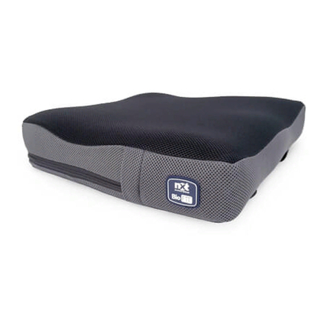
Dynamic NXT Seating Series User manual

Dynamic
Dynamic GyroSet User manual

Dynamic
Dynamic NXT User manual

Dynamic
Dynamic iPortal User manual

Dynamic
Dynamic NXT Seating BioFit User manual

Dynamic
Dynamic DX-SLM User manual

Dynamic
Dynamic nxt Series Instruction Manual

Dynamic
Dynamic iPortal User manual

Dynamic
Dynamic NXT MultiFit User manual
Popular Wheelchair manuals by other brands

Breezy
Breezy UniX Directions for use

Graham Field
Graham Field LUMEX 89101 user manual

Stealth Products
Stealth Products i-Drive Owner's manual & maintenance guide

LEVITAS
LEVITAS ST707 instruction manual

Orliman
Orliman actius ACWC05#41 Instructions for use and care

Motobility
Motobility Solax Genie Plus user manual