Dynamic nxt Series Instruction Manual

INSTALLATION/USERS MANUAL
INSTALLATION/MANUEL D’UTILISATION

EC REP Advena Limited | Pure Offices Plato Close, Warwick CV34 6WE UK / Royaume-Uni
1422791 Ontario Ltd
Dynamic Health Care Solutions
753011 Second Line EHS, Orangeville, ON L9W 5W4 Canada
+519-942-8441 | www.DynamicHCS.com
Complies with:
• ISO 16840-4 Wheelchair Seating -
part 4: Seating Systems for use in
motor vehicles.
• RESNA WC-4:2012 Section 20:
Seating Systems for use in motor
vehicles.
It is recommended that a headrest be
used when the back rest is used for
transport in a motor vehicle.
Conforme à :
• ISO 16840-4 Fauteuils roulants - partie
4 : Systèmes de sièges pour véhicules
automobiles.
• RESNA WC-4:2012 Section 20 :
Systèmes de sièges pour véhicules
automobiles.
Il est recommandé d’utiliser un appui-tête
lorsque le dossier est utilisé pour le trans-
port dans un véhicule automobile.
!
IMPORTANT:
The installation and set up instructions should be
carried out by a qualified technician.
It is important to refer to the wheelchair owner’s
manual for additional safety information related
to the safe operation of the wheelchair.
IMPORTANT:
L’installation et les instructions de configuration
doivent être effectuées par un technicien qualifié.
Il est important de consulter le manuel du
propriétaire du fauteuil roulant pour obtenir des
informations de sécurité supplémentaires relatives
à l’utilisation sécuritaire du fauteuil roulant.

3
TABLE OF CONTENTS TABLE DES MATIÈRES
Mounting Hardware/Tools Required ...........................4
Matériel de montage/Outils requis
Important Installation Information ........................ 4, 5, 6
Informations importantes sur l’installation
Installation Instructions .............................7, 8, 9, 10, 11
Instructions d’installation
Removing the Backrest .......................................12
Retrait du dossier
Removing the Backrest Cover for Washing ...................12
Retrait de la couverture du dossier pour le lavage
Installing Pelvic/Lumbar or Lateral Supports ..................13
Installation de supports pelviens/lombaires ou latéraux
Installing the Head/Neck Support Hardware ..................13
Installation du matériel de support de tête/cou
Armadillo Back / Arrière ...............................14, 15, 16
üFit Customizable Contour Support Back................. 17, 18
Support Contour personnalisable üFit Arrière
Warranty / Garantie...........................................19

4
MOUNTING HARDWARE/TOOLS REQUIRED
MATÉRIEL DE MONTAGE/OUTILS REQUIS
REQUIRED TOOLS / OUTILS REQUIS
ALLEN KEYS / CLÉS ALLEN: 4mm & 5mm
3
10
4
9
11
5
6
7
8
2 121
NIB-1178 LEFT TUBE CLAMP
REAR VIEW
NIB-1004 RIGHT TUBE CLAMP
REAR VIEW
SAME PARTS USED AS
NIB-1178 LEFT CLAMP
PART NO.
ITEM NO.
DESCRIPTION
QTY/CLAMP
NIB-1002
1
G3 CLAMP - INNER
1
NIB-1003
2
G3 CLAMP - OUTER
1
NIB-0999
3
G3 MOUNTING BRACKET-QR
1
NIB-1001
4
G3 CLAMP PLATE
1
NIB-0791
5
M6 FLAT WASHER
2
NIB-1069
6
M6X16mm HSCS-LOW PROFILE
2
NIB-0621
7
WASHER FOR ALUMINUM CLAMP
2
NIB-0813
8
M6X30mm HSCS-LOW PROFILE
2
NIB-1000
9
G3 MOUNTING PIN-LONG
1
NIB-1177
10
G3 MOUNTING PIN-SHORT
1
NIB-0787
11
M6X25mm HSCS-LOW PROFILE
2
NIB-1068
12
G3 CLAMP INNER NUT
1
PINCE À TUBE GAUCHE
NIB-1178 VUE ARRIÈRE
NIB-1004 SERRE-TUBE
DROIT VUE ARRIÈRE
3
10
4
9
11
5
6
7
8
2 121
NIB-1178 LEFT TUBE CLAMP
REAR VIEW
NIB-1004 RIGHT TUBE CLAMP
REAR VIEW
SAME PARTS USED AS
NIB-1178 LEFT CLAMP
PART NO.
ITEM NO.
DESCRIPTION
QTY/CLAMP
NIB-1002
1
G3 CLAMP - INNER
1
NIB-1003
2
G3 CLAMP - OUTER
1
NIB-0999
3
G3 MOUNTING BRACKET-QR
1
NIB-1001
4
G3 CLAMP PLATE
1
NIB-0791
5
M6 FLAT WASHER
2
NIB-1069
6
M6X16mm HSCS-LOW PROFILE
2
NIB-0621
7
WASHER FOR ALUMINUM CLAMP
2
NIB-0813
8
M6X30mm HSCS-LOW PROFILE
2
NIB-1000
9
G3 MOUNTING PIN-LONG
1
NIB-1177
10
G3 MOUNTING PIN-SHORT
1
NIB-0787
11
M6X25mm HSCS-LOW PROFILE
2
NIB-1068
12
G3 CLAMP INNER NUT
1
3
10
4
9
11
5
6
7
8
2 121
NIB-1178 LEFT TUBE CLAMP
REAR VIEW
NIB-1004 RIGHT TUBE CLAMP
REAR VIEW
SAME PARTS USED AS
NIB-1178 LEFT CLAMP
PART NO.
ITEM NO.
DESCRIPTION
QTY/CLAMP
NIB-1002
1
G3 CLAMP - INNER
1
NIB-1003
2
G3 CLAMP - OUTER
1
NIB-0999
3
G3 MOUNTING BRACKET-QR
1
NIB-1001
4
G3 CLAMP PLATE
1
NIB-0791
5
M6 FLAT WASHER
2
NIB-1069
6
M6X16mm HSCS-LOW PROFILE
2
NIB-0621
7
WASHER FOR ALUMINUM CLAMP
2
NIB-0813
8
M6X30mm HSCS-LOW PROFILE
2
NIB-1000
9
G3 MOUNTING PIN-LONG
1
NIB-1177
10
G3 MOUNTING PIN-SHORT
1
NIB-0787
11
M6X25mm HSCS-LOW PROFILE
2
NIB-1068
12
G3 CLAMP INNER NUT
1
LES MÊMES PIÈCES SONT
UTILISÉES EN TANT QUE
PINCE GAUCHE NIB-1178
PART NO.
PARTIE
NO.
ITEM NO.
ARTICLE
NO. DESCRIPTION
QTY/
QTÉ
CLAMP
NIB-1002 1 G3 CLAMP - INNER / G3 CLAMP - INTÉRIEUR 1
NIB-1003 2 G3 CLAMP - OUTER / G3 CLAMP - EXTÉRIEUR 1
NIB-0999 3 G3 MOUNTING BRACKET-QR / G3 SUPPORT DE MONTAGE-QR 1
NIB-1001 4 G3 CLAMP PLATE / G3 PLAQUE DE SERRAGE 1
NIB-0791 5 M6 FLAT WASHER / M6 RONDELLE PLATE 2
NIB-1069 6 M6X16mm HSCS-LOW PROFILE / M6X16mm HSCS-PROFILE BAS 2
NIB-0621 7 WASHER FOR ALUMINUM CLAMP / RONDELLE POUR PINCE EN ALUMINIUM 2
NIB-0813 8 M6X30mm HSCS-LOW PROFILE / M6X30mm HSCS-PROFILE BAS 2
NIB-1000 9 G3 MOUNTING PIN-LONG / G3 GOUPILLE DE MONTAGE 1
NIB-1177 10 G3 MOUNTING PIN-SHORT / G3 BROCHE DE MONTAGE COURTE 1
NIB-0787 11 M6X25mm HSCS-LOW PROFILE / M6X25mm HSCS-PROFILE BAS 2
NIB-1068 12 G3 CLAMP INNER NUT / G3 SERRE-ÉCROU INTERNE 1
IMPORTANT INFORMATION: READ BEFORE INSTALLATION
INFORMATIONS IMPORTANTES : LIRE AVANT L’INSTALLATION
The Quickfit mounting
hardware can accommodate
different size back canes.
3/4”/19mm, 7/8”/22mm and
1”/25mm back canes can be
accommodated without inserts.
Le matériel de montage Quickfit
peut accueillir des cannes arrière
de différentes tailles.
Les cannes arrière 3/4”/19mm,
7/8”/22mm et 1 “/25mm peuvent
être logées sans inserts.

5
IMPORTANT INFORMATION:
FOLLOW BEFORE INSTALLATION
WEIGHT CAPACITY: The weight capacity of the nxt Back is
300lbs/136kg – 400lbs/182kg on 22”/55cm.
23”/58cm – 29”/ 73cm is 550lbs/250kg with 4 point hardware.
Please note that the Quickfit mounting hardware on the nxt Back are
pre-assembled with the cane clamp in the rear most mounting position
to maximize seat depth of the wheelchair. See Fig. 1 below.
The configuration can be changed by orienting the Quickfit cane clamp
forward, providing a forward mounting position. See Fig. 2 below.
Note:The Quickfit mounting hardware provides 3”/ 7.6cm of depth
adjustment, in front of and behind the back canes.
To set the Quickfit mounting hardware in the forward most position:
• Remove the cane clamp from the mounting plate
• Rotate the cane clamp 180° and re-attach it to the mounting plate
• Install clamp as shown in Fig. 2
6"
3 7/8"
BACK POST CENTRELINE
FIG. 2: PIN LOCATION FOR PEDIATRIC
AND ARMADILLO BACKS
FIG. 1: PIN LOCATION FOR ALL BACKS
EXCEPT PEDIATRIC AND ARMADILLO
Please Note: Setting the desired position of the nxt back may
compromise the stability of the wheelchair.
Be aware that the forward and aft position for the backrest will change
the user’s centre of gravity within the wheelchair. A back set in the most
rearward position can significantly reduce the rearward stability of the
wheelchair. In contrast, a more forward back position may reduce the
wheelchair’s forward stability.

6
5
INfoRMATIoNS IMpoRTANTES :
SuIvEz AvANT L'INSTALLATIoN
CAPACITÉ DE POIDS : La capacité de poids de l'arrière du nxt est de
300lbs/136kg – 400lbs/182kg sur 22”/55cm et plus
Veuillez noter que le matériel de montage Quickt de l'arrière du nxt sont pré-
assemblés avec la pince canne dans la position de montage la plus à l'arrière pour
maximiser la profondeur d'assise du fauteuil roulant. Voir la Fig. 1 ci-dessous.
La conguration peut être modiée en orientant la pince Quickt vers l'avant,
offrant ainsi une position de montage vers l'avant. Voir Fig. 2 ci-dessous.
Remarque : Le matériel de montage Quickt offre un ajustement
de profondeur de 3”/7,6 cm devant et derrière les cannes arrière.
Pour régler le matériel de montage Quickt dans la position la plus en avant :
• Retirer la pince à canne de la plaque de montage
• Faites pivoter la pince à canne de 180 ° et xez-la à nouveau
sur la plaque de montage
• Installez la pince comme indiqué dans Fig. 2
6"
3 7/8"
BACK POST CENTRELINE
FIG. 2: PIN LOCATION FOR PEDIATRIC
AND ARMADILLO BACKS
FIG. 1: PIN LOCATION FOR ALL BACKS
EXCEPT PEDIATRIC AND ARMADILLO
Veuillez noter : Le réglage de la position souhaitée de l'arrière du nxt
peut compromettre la stabilité du fauteuil roulant.
Sachez que la position avant et arrière du dossier modiera le centre
de gravité de l'utilisateur dans le fauteuil roulant. Un dossier situé dans
la position la plus en arrière peut réduire considérablement la stabilité
arrière du fauteuil roulant. En revanche, une position plus en avant vers
l'avant peut réduire la stabilité vers l'avant du fauteuil roulant.
FIG. 1 : EMPLACEMENT DE LA
BROCHE POUR TOUS LES DOS
SAUF PÉDIATRIQUE ET ARMADILLO
FIG. 2 : EMPLACEMENT DES BROCHES
POUR LES DOS PÉDIATRIQUE ET
ARMADILLO
ARRIÈRE CENTRE DE POSTE

7
NXT BACK INSTALLATION INSTRUCTIONS
INSTRUCTIONS D’INSTALLATION DE L’ARRIÈRE DU NXT
1. Remove wheelchair back upholstery if
applicable.
Retirez le rembourrage du dossier du
fauteuil roulant, s’il y a lieu.
2. Establish the desired mounting plate
configuration for the user as described
on page 5.
Établissez la configuration de la plaque de
montage souhaitée pour l’utilisateur comme
décrit à la page 5.
3. Loosen the 2 tube clamp screws and
mount Quickfit bracket on the back
canes.
Desserrez les 2 vis de serrage du tube et
montez le support Quickfit sur les cannes
arrière.
4. Position the cane clamp at the height
desired and tighten screws enough to
hold it in place. Full tightening can be
done when back is installed and final
adjustments have been done.
Positionnez la bride de la canne à la hauteur
désirée et serrez suffisamment les vis pour
la maintenir en place. Un serrage complet
peut être effectué lorsque le dossier est
installé et que les derniers ajustements ont
été effectués.
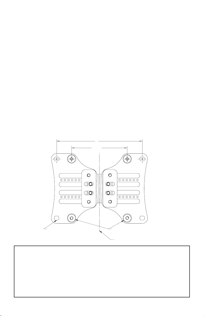
5. Measure the height of the Quickfit
clamp assembly from a fixed position
on the wheelchair and install the
second at the same desired height.
Further, make sure the cane clamp
mounting plates are mounted parallel
with each other. See Fig. 4 below.
Mesurez la hauteur de l’ensemble de
serrage Quickfit à partir d’une position fixe
sur le fauteuil roulant et installez le second à
la même hauteur désirée. En outre, assurez-
vous que les plaques de montage de la
pince à canne sont montées parallèlement
les unes aux autres. Voir la Fig. 4 ci-dessous.
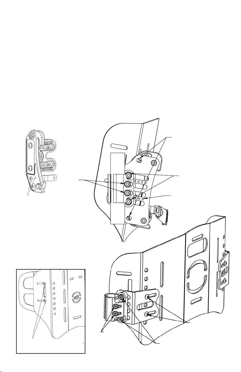
6. All Xtend™Backs can be infinitely
adjusted from 16”/40.6cm to 20”/50.8cm
or Xtend™Low from 13”/33cm to
17”/43cm. Loosen the four cap screws
with a 4mm Allen wrench on the rear
of the backrest, set the backrest to the
desired height and tighten the lock
nuts into place. When the Xtend™is
in its lowest position, tuck the excess
padding behind the seat cushion.
See Fig. 5 below.
Tous les dos Xtend™peuvent être réglés en
continu de 16”/40,6 cm à 20”/50.8cm ou
Xtend™ Low à partir 13”/33cm à 17”/43cm.
Desserrez les quatre vis d’assemblage avec
une clé Allen de 4 mm à l’arrière du dossier,
réglez le dossier à la hauteur désirée et
serrez les contre-écrous en place. Lorsque
le Xtend™arrière est dans sa position la
plus basse, glissez l’excès de rembourrage
derrière le coussin du siège.
Voir la Fig. 5 ci-dessous.
Fig. 4
Cane clamps must be
installed at the same
height and parallel to
each other
Les pinces à canne
doivent être installées
à la même hauteur
et parallèlement les
unes aux autres
Fig. 5
Loosen 4 cap
screws to adjust
back height
Desserrer les 4
vis d’assemblage
pour ajuster
la hauteur du
dossier
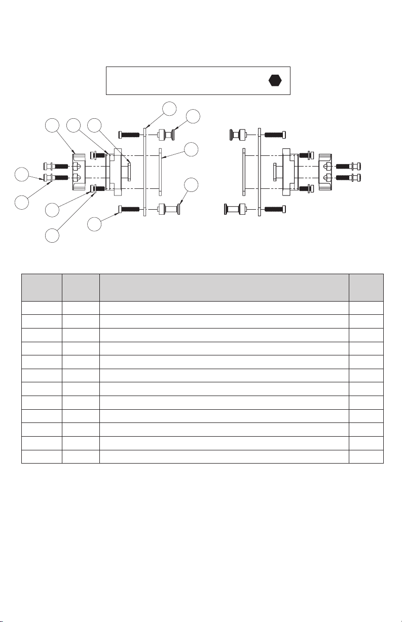
WARNING: DO NOT substitute
hardware provided. Use only high
strength hardware provided.
AVERTISSEMENT : NE PAS
substituer le matériel fourni.
Utilisez uniquement du matériel
à haute résistance fourni

8
STEP
ÉTAPE 1STEP
ÉTAPE 2
CONTINUED: NXT BACK INSTALLATION INSTRUCTIONS
A CONTINUÉ: INSTRUCTIONS D’INSTALLATION DE L’ARRIÈRE DU NXT
7. To install the backrest
on the mounting plates:
Step 1: Insert the top of the
backrest slot onto the top
adjustment pins
Step 2: Rotate the lower
section of the backrest
rearward to lock it into the
locking latch to secure the
backrest in place.
Step 3: Ensure that the latches
lock completely by pushing
down on the release handle or
latches if necessary.
Pour installer le dossier
sur les plaques de montage :
Étape 1 : Insérez le haut de la
fente du dossier sur les broches de
réglage supérieures
Étape 2 : Tournez la section
inférieure du dossier vers l’arrière
pour le verrouiller dans le loquet
de verrouillage pour fixer le dossier
en place.
Étape 3 : Assurez-vous que
les loquets se verrouillent
complètement en appuyant
sur la poignée ou les loquets si
nécessaire.

9
CONTINUED: NXT BACK INSTALLATION INSTRUCTIONS
A CONTINUÉ: INSTRUCTIONS D’INSTALLATION DE L’ARRIÈRE DU NXT
LOOSEN THESE SCREWS TO
ADJUST MOUNTING WIDTH
MINIMUM WIDTH
MAXIMUM WIDTH
LOOSEN THESE SCREWS TO
ADJUST MOUNTING WIDTH
MINIMUM WIDTH
MAXIMUM WIDTH
LARGEUR MINIMALE LARGEUR MINIMALE
AJUSTER LA LARGEUR
DE MONTAGE
8. To ensure the backrest is
properly fitted you may
need to adjust the mounting
hardware to match the back
cane width.
Step 1: Loosen the screws
to adjust the mounting width
and the one-hand release.
Step 2: Make sure the
backrest is centered
horizontally and vertically
between the back canes
and the locking latch on
the bottom is on the
inside of the post
Step 3: When satisfied,
tighten screws.
Step 4: The width adjustable
mounting hardware allows
the backrest to fit 3 sizes of
wheelchair, ie a 16”/40cm
wide back rest can fit a
16”/40cm, a 17”/43cm or
18”/45cm wheelchair.
Pour s’assurer que le dossier est
correctement ajusté, vous devrez
peut-être ajuster le matériel de
montage pour correspondre à la
largeur de la canne arrière.
Étape 1: Desserrez les vis pour
ajuster la largeur de montage et le
dégagement d’une main.
Étape 2 : Assurez-vous que le
dossier est centré horizontalement
et verticalement entre les cannes
arrière et le loquet de verrouillage
sur le fond est à l’intérieur du
poteau
Étape 3 : Une fois satisfait,
serrez les vis.
Étape 4 : La quincaillerie de
montage ajustable en largeur
permet au dossier de s’adapter à
3 tailles de fauteuils roulants, par
exemple un dossier de 16”/40cm
de large peut accueillir un fauteuil
roulant de 16”/40cm, 17”/43cm ou
18”/45cm.

10
CONTINUED: NXT BACK INSTALLATION INSTRUCTIONS
TO LOCK LATCH MOVE THIS
SCREW TO THE ADJACENT
HOLE, THIS WILL PREVENT
THE LATCH FROM LIFTING.
REPLACE SCREW FOR
NORMAL OPERATION.
NOTE: EXTRA HOLE IS NOT
THREADED BUT THE SCREW
WILL MAKE ITS OWN THREAD.
9. Make sure that the overall fit and alignment of the back is correct, if not
make adjustments as required.
10. Secure the cane clamp screws onto each back cane.
11. Setting the depth and recline settings it is best done with the client
seated in the wheelchair. While the client is seated and supported in
the wheelchair, loosen the depth screws on the mounting plate and
set to the desired position. Tighten all screws to lock the backrest in
position. The backrest can be mounted asymmetrically, so be sure that
it is symmetrical if desired.
WIDTH
ADJUSTMENT
SCREWS
DEPTH/ANGLE
ADJUSTMENT SCREWS
TUBE
CLAMPING
SCREWS
LOOSEN THESE SCREWS
TO EXTEND LATERAL
QUICK RELEASE MOUNT
LATERAL CONTOUR
DEPTH ADJUSTMENT
FIXED MOUNT
DEPTH/RECLINE
ADJUSTMENT SCREWS.
USE THESE HOLES IN THE PLATE
AS A REFERENCE GUIDE FOR
SYMMETRICAL ADJUSTMENT ON
THE LEFT AND RIGHT SIDES.
TUBE CLAMPING
SCREWS.
MOUNT PINS IN THESE HOLES
FOR PEDIATRIC AND
ARMADILLO BACKS.

11
9
POUR VERROUILLER LE LOQUET,
DÉPLACEZ CETTE VIS DANS LE
TROU ADJACENT, CELA EMPÊCHERA
LE LOQUET DE SE SOULEVER.
REMPLACEZ LA VIS POUR UN
FONCTIONNEMENT NORMAL.
REMARQUE : LE TROU
SUPPLÉMENTAIRE N'EST PAS ENFILÉ
MAIS LA VIS FERA SON PROPRE FIL.
9. Assurez-vous que l'ajustement global et l'alignement du dos sont
corrects, sinon effectuez les ajustements nécessaires.
10. Fixez les vis de serrage de la canne sur chaque canne arrière.
11. Régler les paramètres de profondeur et d'inclinaison est préférable avec le
client assis dans le fauteuil roulant. Pendant que le client est assis et soutenu
dans le fauteuil roulant, desserrez les vis de profondeur sur la plaque de
montage et réglez à la position désirée. Serrez toutes les vis pour verrouiller
le dossier en position. Le dossier peut être monté asymétriquement, alors
assurez-vous qu'il est symétrique si vous le souhaitez.
INSTRuCTIoNS D'INSTALLATIoN
DE L'ARRIÈRE Du NxT
VIS DE RÉGLAGE
DE LA LARGEUR
VIS DE RÉGLAGE DE LA
PROFONDEUR/ANGLE
VIS DE
SERRAGE
DE TUBES
DESSERRER CES VIS POUR
PROLONGER LES VIS DE
SERRAGE DU TUBE LATÉRAL.
MoNTAgE RApIDE
CoNTouR LATÉRAL
RÉgLAgE DE LA pRofoNDEuR
MoNTAgE fIxE
DEPTH/RECLINE
ADJUSTMENT SCREWS.
USE THESE HOLES IN THE PLATE
AS A REFERENCE GUIDE FOR
SYMMETRICAL ADJUSTMENT ON
THE LEFT AND RIGHT SIDES.
TUBE CLAMPING
SCREWS.
MOUNT PINS IN THESE HOLES
FOR PEDIATRIC AND
ARMADILLO BACKS.
pouR DES RACCoRDS
pEDIATRIquES ET
ARMADILLo.
uTILISEz CES TRouS DANS
LA pLAquE CoMME guIDE
DE RÉfÉRENCE pouR uN
RÉgLAgE SYMÉTRIquE
SuR LES CÔTÉS gAuCHE
ET DRoIT.
vIS DE RÉgLAgE
DE pRofoNDEuR/
INCLINAISoN.
SERRAgE
Du TuBE
LATÉRAL.
A CONTINUÉ: INSTRUCTIONS D’INSTALLATION DE L’ARRIÈRE DU NXT
9
POUR VERROUILLER LE LOQUET,
DÉPLACEZ CETTE VIS DANS LE
TROU ADJACENT, CELA EMPÊCHERA
LE LOQUET DE SE SOULEVER.
REMPLACEZ LA VIS POUR UN
FONCTIONNEMENT NORMAL.
REMARQUE : LE TROU
SUPPLÉMENTAIRE N'EST PAS ENFILÉ
MAIS LA VIS FERA SON PROPRE FIL.
9. Assurez-vous que l'ajustement global et l'alignement du dos sont
corrects, sinon effectuez les ajustements nécessaires.
10. Fixez les vis de serrage de la canne sur chaque canne arrière.
11. Régler les paramètres de profondeur et d'inclinaison est préférable avec le
client assis dans le fauteuil roulant. Pendant que le client est assis et soutenu
dans le fauteuil roulant, desserrez les vis de profondeur sur la plaque de
montage et réglez à la position désirée. Serrez toutes les vis pour verrouiller
le dossier en position. Le dossier peut être monté asymétriquement, alors
assurez-vous qu'il est symétrique si vous le souhaitez.
INSTRuCTIoNS D'INSTALLATIoN
DE L'ARRIÈRE Du NxT
VIS DE RÉGLAGE
DE LA LARGEUR
VIS DE RÉGLAGE DE LA
PROFONDEUR/ANGLE
VIS DE
SERRAGE
DE TUBES
DESSERRER CES VIS POUR
PROLONGER LES VIS DE
SERRAGE DU TUBE LATÉRAL.
MoNTAgE RApIDE
CoNTouR LATÉRAL
RÉgLAgE DE LA pRofoNDEuR
MoNTAgE fIxE
DEPTH/RECLINE
ADJUSTMENT SCREWS.
USE THESE HOLES IN THE PLATE
AS A REFERENCE GUIDE FOR
SYMMETRICAL ADJUSTMENT ON
THE LEFT AND RIGHT SIDES.
TUBE CLAMPING
SCREWS.
MOUNT PINS IN THESE HOLES
FOR PEDIATRIC AND
ARMADILLO BACKS.
pouR DES RACCoRDS
pEDIATRIquES ET
ARMADILLo.
uTILISEz CES TRouS DANS
LA pLAquE CoMME guIDE
DE RÉfÉRENCE pouR uN
RÉgLAgE SYMÉTRIquE
SuR LES CÔTÉS gAuCHE
ET DRoIT.
vIS DE RÉgLAgE
DE pRofoNDEuR/
INCLINAISoN.
SERRAgE
Du TuBE
LATÉRAL.

12
REMOVING THE BACKREST RETRAIT DU DOSSIER
REMOVING THE COVER FOR WASHING & CARE
RETRAIT DE LA COUVERT URE POUR
LE LAVAGE ET LES SOINS
Undo velcro closure &
remove foam pad before
washing outer cover
Défaire la fermeture velcro
et retirer le coussin en
mousse avant de laver la
couverture extérieure
To remove the backrest from the wheelchair
Step 1: Lift on the one hand release lever to release the latches,
push the bottom of the back forward.
Step 2: Lift the backrest off the upper pins to remove completely.
Pour retirer le dossier du fauteuil roulant
Étape 1 : Soulevez le levier de dégagement d’une main pour libérer
les loquets, poussez le bas de l’arrière vers l’avant.
Étape 2: Soulevez le dossier des broches supérieures pour le retirer
complètement.
1. Remove the upholstery from the backrest.
2. For light cleaning of the backrest fabric may be wiped down with a damp cloth.
3. Follow laundering instructions provided with the cover.
1. Retirez le rembourrage du dossier.
2. Pour nettoyer légèrement le tissu du dossier, essuyez-le avec un chiffon humide.
3. Suivez les instructions de lavage fournies avec la couverture.

13
1. Remove the upholstery from the backrest.
2. For light cleaning of the backrest fabric may be wiped down with a damp cloth.
3. Follow laundering instructions provided with the cover.
1. Retirez le rembourrage du dossier.
2. Pour nettoyer légèrement le tissu du dossier, essuyez-le avec un chiffon humide.
3. Suivez les instructions de lavage fournies avec la couverture.
INSTALLING HEAD/NECK SUPPORTS
INSTALLATION DE SUPPORTS DE TÊTE/COU
Attachment slots are stamped into the
back shell for attaching nxt Multifit
Head Support or after market head/
neck supports.
Les fentes d’attaches sont estampées
dans la coquille arrière pour attacher le
support de tête Multifit de nxt ou les
supports de tête/cou d’après-vente.
PELVIC/LUMBAR SUPPORTS &
OPTIONAL LATERAL SUPPORTS
SUPPORTS PELVIENS/LOMBAIRES ET
SUPPORTS LATÉRA UX OPTIONNELS
Pre stamped head/neck rest slots
Emplacements de repos
tête/cou pré-estampés
Pelvic-lumbar support pads
Coussins de soutien pelviens/lombaires
Lateral support pads
Coussins de support latéraux
1. The Pelvic-lumbar support pads can be
uniquely positioned to provide optimal
pelvic positioning and lumbar support.
The supports come uninstalled, allowing
them to be specifically fit to the person
at the time of the back installation. Fit
as shown between fabric and inner shell
of backrest. Hook Velcro on the front of
the pelvic pad attached to the Velcro
compatible fabric of the cover.
Les coussins de soutien pelviens/lombaires
peuvent être positionnés de façon unique
pour offrir un positionnement pelvien et un
soutien lombaire optimaux. Les supports
sont désinstallés, ce qui leur permet d’être
spécifiquement adaptés à la personne lors de
l’installation arrière. Monter comme indiqué
entre le tissu et la coque intérieure du dossier.
Crochet velcro sur le devant du coussin pelvien
attaché au tissu velcro compatible de la couverture.
2. Where additional lateral support is
required, optional lateral supports are.
Fit pads between the fabric and the
shell of the backrest.
Lorsqu’un support latéral supplémentaire est
requis, les supports latéraux optionnels le sont
aussi. Ajuster les coussins entre le tissu et la
coque du dossier.
3. After positioning support pads, seal
velcro closure, reposition cover on the
backrest shell, attach the upholstery.
Après avoir positionné les coussins de support,
sceller la fermeture velcro, repositionner la
couverture sur la coque du dossier, fixer le
rembourrage.

14
Armadillo BACK Armadillo ARRIÈRE
1. Setting Back Height and Angle
The Armadillo back installs, like
all nxt backs, using Universal
Clamps attached to the back
canes. The back height and
angle of the middle shell
segment are adjusted using
these clamps as shown in the
nxt INSTALLATION/USERS
MANUAL.
NOTE: When installing a back,
always ensure the latches are
closed (down) on the lower pins.
Réglage de la hauteur et de l’angle arrière
L’arrière de Armadillo s’installe, comme
tous les arrières de nxt, en utilisant des
pinces universelles attachées aux cannes
arrière. La hauteur et l’angle du dossier
du segment de coque intermédiaire
sont ajustés à l’aide de ces pinces,
comme indiqué dans le MANUEL
D’INSTALLATION/ D’UTILISATION de nxt.
REMARQUE : Lors de l’installation d’un
dossier, assurez-vous toujours que les
loquets sont fermés (vers le bas) sur les
goupilles inférieures.
2. Adjusting Back to
match Chair Width
The Armadillo back is available
in sizes to fit chair widths 14”-
24”. To adjust the mounting
hook width, loosen screws A
and B and slide the mounting
hooks to the correct width and
tighten all screws. Screw A fits
into a fixed threaded hole in
the middle shell segment and
screws B fit into sliding nuts
which also hold the upper
laterals in place if installed. The
hooks are infinitely adjustable
between the minimum and
maximum width and are
normally placed symmetrically
on the back but may be
asymmetrical if required.
Ajuster l’arrière pour assortir
la largeur de la chaise
L’arrière Armadillo est disponible dans
des tailles pour adapter des largeurs de
chaise 14”-24”. Pour ajuster la largeur du
crochet de montage, desserrez les vis A et
B et faites glisser les crochets de montage
à la bonne largeur et serrez toutes les vis.
La vis A s’insère dans un trou taraudé fixe
dans le segment de coquille du milieu
et les vis B dans les écrous coulissants
qui maintiennent également les latéraux
supérieurs en place s’ils sont installés. Les
crochets sont réglables à l’infini entre la
largeur minimale et la largeur maximale et
sont normalement placés symétriquement
sur le dos, mais peuvent être asymétriques
si nécessaire.
A
B
MIDDLE SEGMENT
MOUNTING HOOK
CENTRAL
CHANNEL
NOTE:
Screws A & B on the left and right side of the back must
be used to make width adjustments.
nxt Seating - MAPS Back
Multi Adjustable Postural Support
2. Adjusting Back to match Chair Width
The MAPS back is available in sizes to fit chair widths 14”-24”. To adjust the mounng
hook width, loosen screws A and B and slide the mounng hooks to the correct width and
ghten all screws. Screw A fits into a fixed threaded hole in the middle shell segment and
screws B fit into sliding nuts which also hold the upper laterals in place if installed.
The hooks are infinitely adjustable between the minimum and maximum width and are
normally placed symmetrically on the back but may be asymmetrical if required.
1. Setting Back Height and Angle
The MAPS back installs, like all nxt backs, using Universal Clamps aached to the back canes.
The back height and angle of the middle shell segment are adjusted using these clamps as
shown in the nxt INSTALLATION/USERS MANUAL.
NOTE:
When installing a back, always
ensure the latches are closed (down) on the lower pins.
CANAL
CENTRAL
CROCHET DE MONTAGE
SEGMENT MOYEN
NOTE: Screws A & B on
the left and right side of
the back must be used to
make width adjustments.
REMARQUE : Les vis A
et B du côté gauche et
droit du dos doivent être
utilisées pour effectuer
les réglages de largeur.

15
3. Head Rest Mounting
The Upper and Middle segments
of the Armadillo shell have slots
to accept mounting hardware
for the nxt MultiFit Head Rest.
Choose the location which
provided the best positioning for
the head rest.
Support de tête
Support de tête Les segments supérieur
et central de la coque Armadillo ont
des fentes pour accepter le matériel de
montage pour le repose-tête MultiFit
de nxt. Choisissez l’emplacement qui a
fourni le meilleur positionnement pour
le repose-tête.
4. Lateral Installation and
Adjustment
Upper laterals are held in place
by screws B and the lower laterals
by screws E. These screws thread
into sliding nuts in slots on the
laterals allowing the laterals to be
infinitely adjustable between their
most inner and outer positions
only limited by the postural
requirements of the occupant of
the wheelchair and any structural
components of the wheelchair.
Loosening screws B or E allowing
the laterals to slide will not affect
the positioning of the mounting
hooks.
Installation et réglage latéraux
Les latéraux supérieurs sont
maintenus en place par les vis B
et les latéraux inférieurs par les
vis E. Ces vis se vissent dans les
écrous coulissants dans les fentes
latérales, ce qui permet de régler les
latéraux entre leurs positions les plus
internes et externes uniquement en
fonction des exigences posturales de
l’occupant du fauteuil roulant et des
composants structurels du fauteuil
roulant. Desserrer les vis B ou E en
faisant glisser les latéraux n’affectera
pas le positionnement des crochets
de montage.
CANAL
CENTRAL
B B
EE
UPPER
LATERAL
UPPER
LATERAL
LOWER LATERAL
WITH LARGE PAD
LOWER LATERAL
WITH LARGE PAD
3. Head Rest Mounting
The Upper and Middle segments of the MAPS shell have slots to accept mounng hardware
for the nxt MulFit Head Rest. Choose the locaon which provided the best posioning for
the head rest.
FRONT VIEW
20°
40°
30°
30°
UPPER SEGMENT
LOWER SEGMENT
G
F
HINGE JOINT
HINGE JOINT
4. Lateral Installation and Adjustment
Upper laterals are held in place by screws B and the Lower laterals by screws E. These
screws thread into sliding nuts in slots on the laterals allowing the laterals to be infinitely
adjustable between their most inner and outer posions only limited by the postural
requirements of the occupant of the wheelchair and any structural components of the
wheelchair. Loosening screws B or E allowing the laterals to slide will not affect the
posioning of the mounng hooks.
5. Angle Adjustments
The Upper and Lower segments of the MAPS
shell are individually angle adjustable with
respect to the Middle segment. Loosening
screws G (on both sides of hinge joint) allows
the Upper segment to be lted forward up to
40 degrees or backward up to 20 degrees.
Loosening screws F (on both sides of hinge
joint) allows the Lower segment to be lted
forward or backward up to 30 degrees.
Tightening the screws locks the segment
prevenng a change in angle. Ensure all 8
screws are ghtened.
LATERAL
SUPÉRIEUR LATERAL
SUPÉRIEUR
VUE DE FACE
BAS LATERAL AVEC
GRANDCOUSSIN BAS LATERAL AVEC
GRANDCOUSSIN
B B
EE
UPPER
LATERAL
UPPER
LATERAL
LOWER LATERAL
WITH LARGE PAD
LOWER LATERAL
WITH LARGE PAD
3. Head Rest Mounting
The Upper and Middle segments of the MAPS shell have slots to accept mounng hardware
for the nxt MulFit Head Rest. Choose the locaon which provided the best posioning for
the head rest.
FRONT VIEW
20°
40°
30°
30°
UPPER SEGMENT
LOWER SEGMENT
G
F
HINGE JOINT
HINGE JOINT
4. Lateral Installation and Adjustment
Upper laterals are held in place by screws B and the Lower laterals by screws E. These
screws thread into sliding nuts in slots on the laterals allowing the laterals to be infinitely
adjustable between their most inner and outer posions only limited by the postural
requirements of the occupant of the wheelchair and any structural components of the
wheelchair. Loosening screws B or E allowing the laterals to slide will not affect the
posioning of the mounng hooks.
5. Angle Adjustments
The Upper and Lower segments of the MAPS
shell are individually angle adjustable with
respect to the Middle segment. Loosening
screws G (on both sides of hinge joint) allows
the Upper segment to be lted forward up to
40 degrees or backward up to 20 degrees.
Loosening screws F (on both sides of hinge
joint) allows the Lower segment to be lted
forward or backward up to 30 degrees.
Tightening the screws locks the segment
prevenng a change in angle. Ensure all 8
screws are ghtened.

16
5. Angle Adjustments
The Upper and Lower segments
of the Armadillo shell are
individually angle adjustable with
respect to the Middle segment.
Loosening screws G (on both sides
of hinge joint) allows the Upper
segment to be tilted forward up to
40 degrees or backward up to 20
degrees. Loosening screws F (on
both sides of hinge joint) allows the
Lower segment to be tilted forward
or backward up to 30 degrees.
Tightening the screws locks the
segment preventing a change in
angle. Ensure all 8 screws
are tightened.
Ajustements d’angle
Les segments supérieur et inférieur
de la coque Armadillo sont
individuellement réglables en angle
par rapport au segment central.
Desserrer les vis G (des deux côtés
du joint de charnière) permet
d’incliner le segment supérieur de 40
degrés vers l’avant ou de 20 degrés
vers l’arrière. Desserrer les vis F (des
deux côtés du joint de charnière)
permet d’incliner le segment
inférieur vers l’avant ou vers l’arrière
jusqu’à 30 degrés. Le serrage des vis
bloque le segment en empêchant un
changement d’angle. Assurez-vous
que les 8 vis sont serrées.
B B
EE
UPPER
LATERAL
UPPER
LATERAL
LOWER LATERAL
WITH LARGE PAD
LOWER LATERAL
WITH LARGE PAD
3. Head Rest Mounting
The Upper and Middle segments of the MAPS shell have slots to accept mounng hardware
for the nxt MulFit Head Rest. Choose the locaon which provided the best posioning for
the head rest.
FRONT VIEW
20°
40°
30°
30°
UPPER SEGMENT
LOWER SEGMENT
G
F
HINGE JOINT
HINGE JOINT
4. Lateral Installation and Adjustment
Upper laterals are held in place by screws B and the Lower laterals by screws E. These
screws thread into sliding nuts in slots on the laterals allowing the laterals to be infinitely
adjustable between their most inner and outer posions only limited by the postural
requirements of the occupant of the wheelchair and any structural components of the
wheelchair. Loosening screws B or E allowing the laterals to slide will not affect the
posioning of the mounng hooks.
5. Angle Adjustments
The Upper and Lower segments of the MAPS
shell are individually angle adjustable with
respect to the Middle segment. Loosening
screws G (on both sides of hinge joint) allows
the Upper segment to be lted forward up to
40 degrees or backward up to 20 degrees.
Loosening screws F (on both sides of hinge
joint) allows the Lower segment to be lted
forward or backward up to 30 degrees.
Tightening the screws locks the segment
prevenng a change in angle. Ensure all 8
screws are ghtened.
SEGMENT SUPÉRIEUR
JOINT DE CHARNIÈRE
JOINT DE
CHARNIÈRE
SEGMENT INFÉRIEUR

17
üFit™CUSTOMIZABLE CONTOUR SUPPORT BACK
1. Customization
üCube™sets can be removed
completely, or cut for greater
customization. To remove/cut,
first unzip both zipper pulls on
the cover and fold the front of
the cover down. Remove the
center foam overlay, to expose
the üCube™. To remove the
üCube™, grasp the cube set by
the darker coloured closed cell
foam base and gently pull up –
the cube will release from the
back shell.
If cutting, cut the üCube™once it has been removed, and re-install on back
shell by aligning the studs (white pins on the underside of the üCube™) with
the holes and pushing back into place until an audible click is heard. Once
all desired customization is complete, re-install the center foam overlay and
zip-up the cover.
2. Installing Head Support
To install a head support on the üFit™
,
you must remove the cover fabric that
overlays the slots which the
head support is installed
in. Coneveniently, there
is a punched template to
follow. Simply connect
the ends of the existing
cuts with scissors or a
knife to remove the
rectangle of fabric.
Next remove the back cover and then the üCube™that are in the area
around the mounting slots. Install the mounting hardware and adjust the
angle as desired by rotating the bracket slightly either clockwise or counter
clockwise.
Reassemble the üCube™and cover ensuring the mounting hardware fits
through the hole cut into the cover.

18
14
SUPPORT DE CONTOUR ARRIÈRE
PERSONNALISABLE üFit
1. Personnalisation
Les jeux üCubes™ peuvent être
complètement supprimés ou
coupés pour une plus grande
personnalisation. Pour retirer/
couper, commencez par
dézipper les deux fermetures
à glissière sur le couvercle et
pliez l'avant du couvercle vers
le bas. Retirez le revêtement
de mousse central pour exposer
les üCubes™. Pour retirer les
üCubes™, saisissez le cube par
la base de mousse à cellules
fermées de couleur foncée et
tirez doucement – le cube se
détachera de la coque arrière.
Si vous coupez, coupez l'üCube™ une fois qu'il a été retiré et réinstallez-le
sur la coque arrière en alignant les goujons (goupilles blanches sur la face
inférieure de l'üCube™) avec les trous et repoussez en place jusqu'à entendre
un clic audible. Une fois que toute la personnalisation souhaitée est terminée,
réinstallez le revêtement de mousse central et zippez le couverture.
2. Installation du support de tête
Pour installer un support de tête sur le üFit™,
vous devez retirer le tissu de couverture qui
recouvre les fentes dans lesquelles
le support de tête est installé.
Idéalement, il y a un modèle
perforé à suivre. Il suffit de
connecter les extrémités des
coupes existantes avec des
ciseaux ou un couteau pour
enlever le rectangle de tissu.
Ensuite, retirez la couverture arrière, puis les cubes qui se trouvent dans
la zone autour des fentes de montage. Installez le matériel de montage et
réglez l'angle comme vous le souhaitez en tournant légèrement le support
dans le sens des aiguilles d'une montre ou dans le sens anti-horaire.
Remonter les üCubes™ et le couvercle en s'assurant que le matériel
de montage passe dans le trou percé dans la couverture.

19
WARRANTY POLICY POLITIQUE DE GARANTIE
The nxt™Seating Series Back Support has a Limited Warranty for 24 months
from the date of delivery to the original purchaser. If any defect in material or
workmanship is found, the manufacturer will repair or replace the component,
at our discretion. This limited warranty does not cover daily wear and tear or
damage that is a result of mishandling, misuse, neglect, or not following the
care and maintenance instructions. Your back support cover is under warranty
for 90 days. The warranty includes damage due to workmanship, material
defects or errors caused by the manufacturer. This warranty does not apply to
cigarette burns, damage to the cover by sharp objects that may cause tears,
or damage as a result of not following the washing instructions. Claims and
repairs should be processed through your nearest authorized dealer. A copy
of the invoice issued to the purchaser of the product may be required prior to
processing a warranty claim.
Le support dorsal Seating Serie nxt™a une garantie limitée de 24 mois à
compter de la date de livraison à l’acheteur d’origine. Si un défaut de
matériel ou de fabrication est constaté, le fabricant réparera ou remplacera
le composant, à notre discrétion. Cette garantie limitée ne couvre pas l’usure
quotidienne ou les dommages résultant d’une mauvaise manipulation, d’une
mauvaise utilisation, d’une négligence ou du non-respect des instructions
d’entretien et de maintenance. Votre couverture du support arrière est
sous garantie pendant 90 jours. La garantie inclut les dommages dus à la
fabrication, aux défauts matériels ou aux erreurs causées par le fabricant.
Cette garantie ne s’applique pas aux brûlures de cigarettes, aux dommages
causés à la couverture par des objets tranchants susceptibles de provoquer
des déchirures ou aux dommages résultant du non-respect des instructions
de lavage. Les réclamations et les réparations doivent être traitées par le
concessionnaire autorisé le plus proche. Une copie de la facture émise à
l’acheteur du produit peut être requise avant le traitement d’une réclamation
de garantie.

Dynamic Health Care Solutions
T (866) 875-2877 • F (866) 875-2878
www.DynamicHCS.com
By
This manual suits for next models
1
Table of contents
Other Dynamic Wheelchair manuals

Dynamic
Dynamic DX-SLM User manual

Dynamic
Dynamic NXT Seating Series User manual

Dynamic
Dynamic NXT User manual

Dynamic
Dynamic NXT Seating BioFit User manual

Dynamic
Dynamic NXT MultiFit User manual

Dynamic
Dynamic iPortal User manual

Dynamic
Dynamic NXT User manual

Dynamic
Dynamic iPortal User manual

Dynamic
Dynamic GyroSet User manual
Popular Wheelchair manuals by other brands

Sunrise Medical
Sunrise Medical Quickie installation instructions

Handicare
Handicare IBIS XA Service manual

Invacare
Invacare Spectra XTR instruction manual

Nissin
Nissin CB user manual

Drive DeVilbiss Healthcare
Drive DeVilbiss Healthcare DSF 130 Instructions for use

Travel Buggy
Travel Buggy CITY 2 PLUS manual