Eaton Cutler-Hammer VCP-WR Series 18 User manual

I.B. 8295A61H03
Effective 7/97
Cutler-Hammer
Instructions for the Use, Operation and Maintenance of The
Red Line Type VCP-WR Vacuum Circuit Breaker Elements
VCP-WR Series 29
VCP-WR Series 20
VCP-WR Series 18


I.B. 8295A61H03 Page iii
Effective 7/97
Cutler-Hammer
Power Distribution Components Division
Five Parkway Center
Pittsburgh, PA 15220
All possible contingencies which may arise during installation, operation or maintenance, and all details and
variations of this equipment do not purport to be covered by these instructions. If further information is
desired by purchaser regarding his particular installation, operation or maintenance of particular equipment,
contact a Cutler-Hammer representative.
IMPROPERLY INSTALLING OR MAINTAINING
THESE PRODUCTS CAN RESULT IN DEATH, SERI-
OUS PERSONAL INJURY, OR PROPERTY DAMAGE.
READ AND UNDERSTAND THESE INSTRUCTIONS
BEFORE ATTEMPTING ANY UNPACKING, ASSEM-
BLY, OPERATION OR MAINTENANCE OF THE CIR-
CUIT BREAKERS.
INSTALLATION OR MAINTENANCE SHOULD BE
ATTEMPTED ONLY BY QUALIFIED PERSONNEL.
THIS INSTRUCTION BOOK SHOULD NOT BE CON-
SIDERED ALL INCLUSIVE REGARDING INSTALLA-
TION OR MAINTENANCE PROCEDURES. IF FUR-
THER INFORMATION IS REQUIRED, YOU SHOULD
CONTACT CUTLER-HAMMER.
THE CIRCUIT BREAKER ELEMENTS DESCRIBED IN
THIS BOOK ARE DESIGNED AND TESTED TO
OPERATE WITHIN THEIR NAMEPLATE RATINGS.
OPERATION OUTSIDE OF THESE RATINGS MAY
CAUSE THE EQUIPMENT TO FAIL, RESULTING IN
DEATH, BODILY INJURY AND PROPERTY DAM-
AGE.
ALL SAFETY CODES, SAFETY STANDARDS
AND/OR REGULATIONS AS THEY MAY BE
APPLIED TO THIS TYPE OF EQUIPMENT MUST BE
STRICTLY ADHERED TO.
THESE CIRCUIT BREAKER ELEMENTS ARE
DESIGNED TO BE INSTALLED PURSUANT TO
AMERICAN NATIONAL STANDARDS INSTITUTE
(ANSI) STANDARD C37.59. SERIOUS INJURY,
INCLUDING DEATH, CAN RESULT FROM FAILURE
TO FOLLOW THE PROCEDURES OUTLINED IN THIS
MANUAL. THESE CIRCUIT BREAKER ELEMENTS
ARE SOLD PURSUANT TO A NON-STANDARD PUR-
CHASING AGREEMENT WHICH LIMITS THE LIABIL-
ITY OF THE MANUFACTURER.
!
WARNING
!
WARNING

I.B. 8295A61H03
Page iv
Effective 7/97
TABLE OF CONTENTS
Page
SECTION 1 INTRODUCTION..................................................................................................................................1
1-1 Type VCP-WR (Red Line Series) Ratings.........................................................................................................1
1-2 Type VCP-WR Outlines and Dimensions..........................................................................................................2
SECTION 2 SAFE PRACTICES..............................................................................................................................9
SECTION 3 RECEIVING, HANDLING AND STORAGE.......................................................................................10
3-1 Receiving.........................................................................................................................................................10
3-2 Handling..........................................................................................................................................................10
3-3 Storage ...........................................................................................................................................................10
3-4 Type VCP-WR Breaker Weights.....................................................................................................................11
SECTION 4 INSPECTION AND OPERATION ......................................................................................................19
4-1 Initial Inspection...............................................................................................................................................19
4-2 Manual Operation Check.................................................................................................................................19
4-3 Interface Verification........................................................................................................................................19
SECTION 5 DESCRIPTION AND OPERATION....................................................................................................20
5-1 Circuit Breaker Elements.................................................................................................................................20
5-2 Interrupter Assembly.......................................................................................................................................20
5-2.1 Vacuum Interrupter.............................................................................................................................20
5-2.2 Contact Erosion Indicator...................................................................................................................22
5-2.3 “T” Cutout Loading Spring Indicator ...................................................................................................23
5-2.4 Contact Wipe and Stroke ...................................................................................................................23
5-3 Stored Energy Mechanism..............................................................................................................................23
5-3.1 Operation of Stored Energy Mechanism ............................................................................................23
5-3.2 Charging.............................................................................................................................................24
5-3.3 Closing Operation...............................................................................................................................24
5-3.4 Tripping Operation..............................................................................................................................24
5-3.5 Trip Free Operation............................................................................................................................24
5-4 Control Schemes.............................................................................................................................................24
5-4.1 Timing.................................................................................................................................................27
5-4.2 Terminal Blocks..................................................................................................................................27
5-5 Operations Counter.........................................................................................................................................27

I.B. 8295A61H03 Page v
Effective 7/97
Page
SECTION 6 BREAKER ELEMENT INTERFACING..............................................................................................28
6-1 Introduction......................................................................................................................................................28
6-2 General Guidelines..........................................................................................................................................28
6-2.1 Electrical Clearances..........................................................................................................................28
6-2.2 Interphase Barriers.............................................................................................................................28
6-2.3 Front Cover (Faceplate) .....................................................................................................................28
6-2.4 Compartment Interface Verification....................................................................................................29
6-3 Series 18 Breaker Element Interfaces.............................................................................................................29
6-3.1 Initial Interfacing Steps.......................................................................................................................29
6-3.2 Electrical Interfaces............................................................................................................................29
6-3.3 Mechanical Interfaces ........................................................................................................................29
6-4 Series 20 Breaker Element Interfaces.............................................................................................................31
6-4.1 Initial Interfacing Steps.......................................................................................................................31
6-4.2 Electrical Interfaces............................................................................................................................32
6-4.3 Mechanical Interfaces ........................................................................................................................32
6-5 Series 29 Breaker Element Interfaces.............................................................................................................33
6-5.1 Initial Interfacing Steps.......................................................................................................................33
6-5.2 Electrical Interfaces............................................................................................................................33
6-5.3 Mechanical Interfaces ........................................................................................................................33
SECTION 7 INSPECTION AND MAINTENANCE.................................................................................................35
7-1 Introduction......................................................................................................................................................35
7-2 Frequency of Inspection..................................................................................................................................35
7-3 Inspection and Maintenance Procedures........................................................................................................36
7-4 Vacuum Interrupter Integrity Test....................................................................................................................37
7-5 Contact Erosion and Wipe...............................................................................................................................37
7-6 Insulation.........................................................................................................................................................38
7-7 Insulation Integrity Check................................................................................................................................38
7-8 Primary Circuit Resistance Check...................................................................................................................39
7-9 Mechanism Check...........................................................................................................................................39
7-10 Lubrication.......................................................................................................................................................39
7-11 Troubleshooting Chart.....................................................................................................................................41
SECTION 8 RENEWAL PARTS............................................................................................................................44
8-1 General ...........................................................................................................................................................44
8-2 Ordering Instructions.......................................................................................................................................44

I.B. 8295A61H03
Page vi
Effective 7/97
FIGURES
Figure Title Page
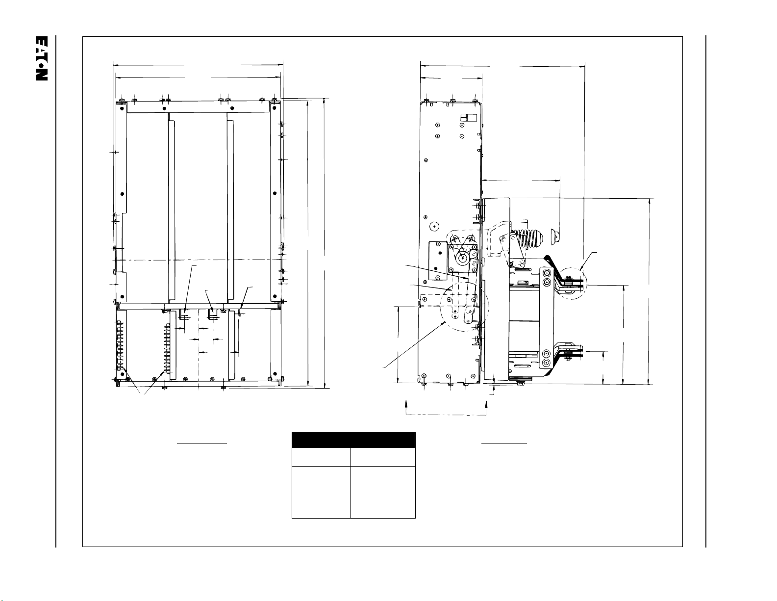
1-1 Type VCP-WR Series 18 Element Outlines and Dimensions (inches)......................................................2
1-2 Type VCP-WR Series 20 Element Outlines and Dimensions (inches)......................................................4
1-3 Type VCP-WR Series 29 Element Outlines and Dimensions (inches)......................................................6
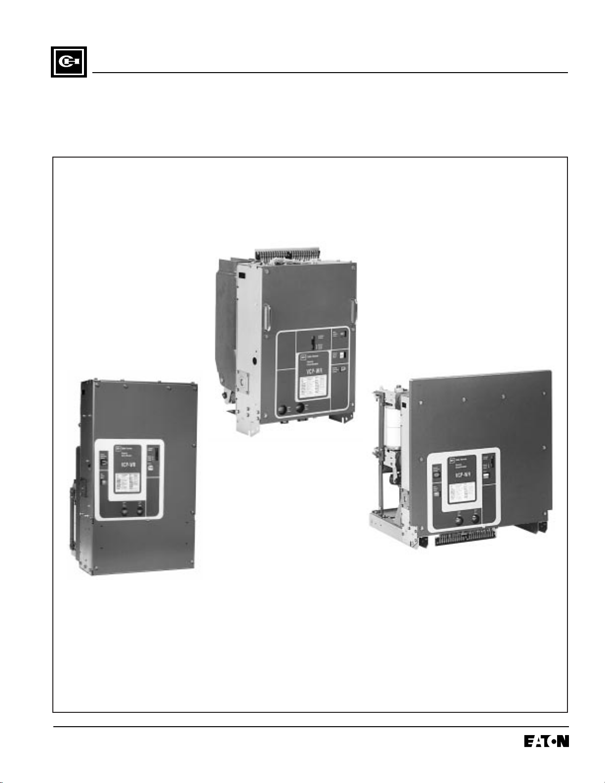
3-1 Front View VCP-WR Series 18................................................................................................................12
3-2 Rear View VCP-WR Series 18 ................................................................................................................13
3-3 Front View VCP-WR Series 20................................................................................................................14
3-4 Rear View VCP-WR Series 20 ................................................................................................................15
3-5 Front View VCP-WR Series 29................................................................................................................16
3-6 Rear View VCP-WR Series 29 ................................................................................................................17
3-7 Typical VCP-WR Escutcheon..................................................................................................................18
5-1 Typical VCP-WR Front Mounted Mechanism..........................................................................................21
5-2 Type VCP-WR Series 20 Interrupter Assemblies....................................................................................22
5-3 Type VCP-WR Series 18 Interrupter Assemblies....................................................................................22
5-4 Type VCP-WR Series 29 Interrupter Assemblies....................................................................................22
5-5 Typical Cutler-Hammer Vacuum Interrupter Shown Attached to
Non-Sliding Current Transfer System......................................................................................................23
5-6 Closing Cam and Trip Linkage ................................................................................................................25
5-7 Charging Schematic ................................................................................................................................26
6-1 Typical VCP-WR Front Cover, Nameplate and Operational Indicators...................................................29
6-2 Typical VCP-WR “DC” and “AC” Control Schematics..............................................................................30
6-3 Series 18 Primary Connection.................................................................................................................31
6-4 Series 18 Showing Bottom Accessed Interlocks and MOC Operator......................................................31
6-5 Series 20 Primary Connection.................................................................................................................32
6-6 Series 20 Showing Bottom Accessed Interlocks and MOC Operator......................................................33
6-7 Series 29 Primary Connection.................................................................................................................34
6-8 Series 29 Showing Bottom Accessed Interlocks and MOC Operator......................................................34
7-1 Lubrication Points....................................................................................................................................35
7-2 Vacuum Interrupter Showing Contact Erosion Indicator with Breaker Open...........................................38
7-3 Vacuum Interrupter Showing Contact Erosion Indicator with Breaker Closed.........................................38
7-4 Typical “T” Contact Wipe Indicator ..........................................................................................................39
7-5 Wipe Indication Procedure.......................................................................................................................40
TABLES
Table Title Page
1.1 Type VCP-WR (Red Line Series) Ratings.................................................................................................1
3.1 VCP-WR Breaker Weights (pounds) .......................................................................................................11
5.1 Breaker Timing ........................................................................................................................................27
7.1 Test Voltage.............................................................................................................................................37
7.2 Typical Resistance Measurements..........................................................................................................39
8.1 Recommended VCP-WR Spare Parts.....................................................................................................45

I.B. 8295A61H03 Page 1
Effective 7/97
SECTION 1: INTRODUCTION
The purpose of this book is to provide instructions for
unpacking, storage, use, operation and maintenance of
Type VCP-WR Vacuum Circuit Breakers. VCP-WR is a
vacuum interrupting element designed for value added
construction. The VCP-WR Red Line family of circuit
breaker elements is comprised of three element types
(Series 18, Series 20 and Series 29). The nominal
widths are 18 inches for Series 18, 20 inches for Series
20 and 29 inches for Series 29. Any one of the three
available elements can be used as a retrofitting drawout
breaker when the customer provides and combines the
appropriate cell interface, truck, levering mechanism,
secondary connections, interlocks and other accessory
items with the VCP-WR element. VCP-WR elements
can also be used for fixed breaker applications with oth-
ers responsible for all required interfaces.
SATISFACTORY PERFORMANCE OF THESE
BREAKERS IS CONTINGENT UPON PROPER APPLI-
CATION, CORRECT INSTALLATION AND ADE-
QUATE MAINTENANCE. THIS INSTRUCTION BOOK
MUST BE CAREFULLY READ AND FOLLOWED IN
ORDER TO OBTAIN OPTIMUM PERFORMANCE FOR
LONG USEFUL LIFE OF THE CIRCUIT BREAKERS.
TYPE VCP-WR BREAKERS ARE PROTECTIVE
DEVICES, AS SUCH, THEY ARE MAXIMUM RATED
DEVICES. THEREFORE, THEY SHOULD NOT
UNDER ANY CIRCUMSTANCES BE APPLIED OUT-
SIDE THEIR NAMEPLATE RATINGS.
!
WARNING
Identification Rated Values Related Required Capabilities
Current Nominal Nominal Voltage Insulation Level Rated Rated Rated Current Values
Rated Rated Voltage 3-Phase Rated Rated Rated Withstand Inter- Permis- Max. Maxi- 3 Sec. Closing
Contin- Short Class MVA Max. Voltage Test Voltage rupting sible Voltage mum Short and
uous Circuit Class Voltage Range Time Tripping Divided Sym. Time Latching
Current Current Factor Delay by K Inter- Current Capability
at (at rupting Carrying (Momen-
60 Hz Rated Capability Capability tary)
Max. K Times Rated 2.7 K
kV) Short Circuit Times
Low Current Rated
Fre- Impulse KI Short
Circuit I E K quencey Y E/K Circuit
Breaker Series kV MVA Current
Type Width Amps kA rms Class Class kV rms kV rms kV Crest Cycles Sec. kV rms kA rms kA rms kA Crest
VCP-WR Vacuum Circuit Breaker
50 VCP-WR 250 18, 20, 29 1200 29 4.16 250 4.76 1.24 19 60 5 2 3.85 36 36 97
18, 20, 29 2000
29 3000
50 VCP-WR 350 20, 29 1200 41 4.16 350 4.76 1.19 19 60 5 2 4.0 49 49 132
20, 29 2000
29 3000
75 VCP-WR 500 18, 29 1200 33 7.2 500 8.25 1.25 36 95 5 2 6.6 41 41 111
18, 29 2000
29 3000
150 VCP-WR 500 18 600 18 13.8 500 15 1.30 36 95 5 2 11.5 23 23 62
18, 29 1200
18, 29 2000
29 3000
150 VCP-WR 750 18, 29 1200 28 13.8 750 15 1.30 36 95 5 2 11.5 36 36 97
18, 29 2000
29 3000
150VCP-WR1000 29 1200 37 13.8 1000 15 1.30 36 95 5 2 11.5 48 48 130
29 2000
29 3000
150VCP-WR1500 29 1200 63 13.8 1600 15 1.0 36 95 5 2 15.0 63 63 170
29 2000 or
29 3000 1500
Table 1.1 VCP-WR Ratings
1-1 TYPE VCP-WR (RED LINE SERIES) RATINGS

I.B. 8295A61H03
Page 2
Effective 7/97
1-2 TYPE VCP-WR OUTLINES AND DIMENSIONS
9.58 19.16
A
A
B
B
12.38
9.25“A” “A” 9.25
POLE
UNIT POLE
UNIT POLE
UNIT
27.69
25.19
Close
Floor
Tripper Trip
Floor
Tripper 18.25 10.88 7.23
5.81
MOC
Operator
.13
VCP-WR
2.47
.38 Dia. (2) Near Side
and (2) Far Side
for Mounting 6.88
6.04 3.50 11.45
.77
.77
2.47
Ref
See Expanded
View, Next Page
30.16 Ref
600A, 1200A and
2000A Breaker
Outline
10.70 13.33 (50/350)
12.06
.63 1200A/2000A
.25 600A
19.33 (50/350)
7.83
2.96
2.33 .38
Dia
1.60 7.84 2.00
1.44
1.10
.57
Stroke
Closed
Open
Optional
Top MOC
Operator
19.75
10.33 (50/350)
8.40 (50/350) This Dim.
for 50/350
Only
Figure 1-1 VCP-WR Series 18 Element Outlines and Dimensions (inches)
Note: (1) Refer to page 4 for applicable rating and dimension table covering Series 18 only.
(2) Refer to page 4 for exploded view of terminal block.

I.B. 8295A61H03 Page 3
Effective 7/97
Figure 1-1 VCP-WR Series 18 Element Outlines and Dimensions (inches) -continued
“A” “A”
.35 Dia
(3)
.13 “B” 2.00
1.00 .50
18.50 Ref
19.16 Ref
2.00
7.84 Ref7.83 Ref
19.75 Ref
2.96
Ref
5.81
Optional
Top MOC
Operator
19.33 (50/350)
8.40 Ref (50/350 Only)
This Dim. for
50/350 Only
1.44
.50
10.88
9.25
7.23
5.81 1.58
.312 Hex
Bolts (6)
1.94
1.37 1.05
1.44 .77
.75
.83
.88
5.71
6.87
MOC Operator
.219 R Slot (2)
for Mounting
.438 Dia (2)
for Mounting
.98
5.64
7.50
17.02
16.54
15.35
5.90
5.50
5.64
Trip Floor
Tripper
Close Floor
Tripper
.65
3.50
Ref
.87
.312-18
Clinch
Nuts (9)
Stroke
Close and Trip
Floor Trippers .750
.500 Roller Dia
1.00
MOC Operator
.750 Roller Dia
.63
Stroke
1.25
3.13
.57 .86 1.10
12345678910
11 12 13 14 15 1617 18 19 20 21 22 23 24 2.5
12.38
View A - A View B - B
Expanded View Exploded View of Terminal Block
Series 18 Rating/Dimension Table
Type Continuous Dimension Dimension
Current (60HZ) “A” “B”
50 VCP-WR 250 1200A 5.90 3.00
2000A 5.90 4.00
50 VCP-WR 350 1200A 5.90 3.00
2000A 5.90 4.00
75 VCP-WR 500 1200A 6.50 3.00
2000A 6.50 4.00
150 VCP-WR 500 600A 6.50 3.00
1200A 6.50 3.00
2000A 6.50 4.00
150 VCP-WR 750 1200A 6.50 3.00
2000A 6.50 4.00

I.B. 8295A61H03
Page 4
Effective 7/97
20.66
20.00
34.57
35.15
Trip
Close MOC
SW
Drive
1.75
1.75
4.85
Secondary
Wiring TB
See View
Y - Y
9.39
Trip & Close
Floor Tripper
.18 A
A
MOC
9.62
7.66 20.27
See View
X - X
22.85
12.15
4.03
Figure 1-2 VCP-WR Series 20 Element Outlines and Dimensions (inches)
Front View Side View
Series 20 Rating Table
Type Continuous
Current (60HZ)
50 VCP-WR 250 1200A
2000A
50 VCP-WR 350 1200A
2000A

I.B. 8295A61H03 Page 5
Effective 7/97
Figure 1-2 VCP-WR Series 20 Element Outlines and Dimensions (inches) -continued
7.00 7.00
.406 Dia. Typ.
2.38
3.19
12.30
5.30
.44 .88 1.19
20.66
.312 - 18
Clinch Nut
(3)
.375
Dia. (4)
2.63
7.125
.78
1.19
1.19
Secondary
Wiring
Access to TB
1.16
1.16
16.00
Close Trip
8.00
1.09
1.09
6.745.75
1.875 3.018 1.50
.88
6.875
4.96
MOC
SW
1.31
.28
Nom.
.38 ±.010
Bus Connection.
*Important - This Gap
Dimension Must
Be Maintained.
MOC
Floor
Tripper
1.25
.63
Travel 1.31
1.56
1.73
.56
3.13
Top View View A - A
Bottom Pan View Y - Y
View X - X
Note: Refer to page 5 for applicable rating table covering Series 20 only.

I.B. 8295A61H03
Page 6
Effective 7/97
Figure 1-3 VCP-WR Series 29 Element Outlines and Dimensions (inches)
29.13
C
VCP-WR
4.59
1.75
1.75
AB
ABMOC Interface
Opening - Closing
Floor Trippers (See TB Aux. View)
7.78 Ref.
F
ront
Travel - .62
3.12
1.25
.50 Dia.
7.78 Ref.
Front
1.31
1.56
.314 Dia.
.317
.56
Travel - 1.16
Bracket w/Term Blocks
Breaker Bottom Pan (Front View)
3.89 12.12
1.25
2
13456789
10 11 13
12 14 15 16 17 18 19 20 21 22 23 24
Front View
Section A-A
(Opening-Closing Floor Tripper)
Section B-B
(MOC Switch Operator Bar)
Side View
TB Auxiliary View
Note: Refer to page 9 for applicable rating and
dimension table covering Series 29 only.

I.B. 8295A61H03 Page 7
Effective 7/97
Figure 1-3 VCP-WR Series 29 Element Outlines and Dimensions (inches) -continued
SeeDetailX
10
10
7.78
Ref B
A
12
13.88
.503/.505
Dia.(2)
2.25 20.875
24.63 Ref
SeeDetailY
10
10
C
L
B
ARemove
andReplace
SeeDet.D
12
13.88
1.00
2.25 20.875
24.63 Ref
7.78
Ref
C
L
C
LC
L
.12 x 4 or
5 CU. Bar
as Req.
Flex.
Conn.
.12 x 4 or
5 CU. Bar
as Req.
Flex.
Conn.
1.0
1.0 1.0
1.0
1.0
1.0 1.28 .28
4.0
Ref
3.0
Ref
.375Dia
(3)For
.312
Dia.
Hwd
Section Figure 1 Section Figure 2
Detail X Detail Y
Note: Refer to page 9 for applicable rating and
dimension table covering Series 29 only.

I.B. 8295A61H03
Page 8
Effective 7/97
Figure 1-3 VCP-WR Series 29 Element Outlines and Dimensions (inches) -continued
– 2-.12 x 4 Cu Bar Can Be Straight Off Stud or Turned Up or Down.
Top Stud
1.0 1.28
.5
.5
12
Bottom Stud Bottom Stud
12
1.28
1.0
Top Stud
B
Top Stud .5
1.28
1.0 12
.5
Bottom Stud
– 2-.12 x 5 Cu Bar can be Straight Off Stud
or Turned Up or Down. – 3000A-1-.5 x 5 Cu Bar
.5 .25
Bottom Stud
.28
.5 .25
12
Top Stud
B
1.0
Detail A Detail B
Detail C Detail D
Series 29 Rating/Dimension Table
Continuous Stud Insu-
Current Detail lator
Type (60Hz) -A- -B- -C- Figure
50 VCP-WR 250 1200A A 3.5 17.38 29.19 1
2000A C 3.5 17.38 29.19 1
3000A D 3.5 16.38 30.97 2
50 VCP-WR 350 1200A B 3.5 17.38 30.97 1
2000A C 3.5 17.38 30.97 1
3000A D 3.5 16.38 30.97 2
75 VCP-WR 500 1200A A 6.0 19.88 29.19 1
2000A C 6.0 19.88 29.19 1
3000A D 6.0 18.88 30.97 2
150 VCP-WR 500 1200A A 6.0 19.88 29.19 1
2000A C 6.0 19.88 29.19 1
3000A D 6.0 18.88 30.97 2
150 VCP-WR 750 1200A A 6.0 19.88 29.19 1
2000A C 6.0 19.88 29.19 1
3000A D 6.0 18.88 30.97 2
150 VCP-WR 1000 1200A B 6.0 19.88 30.97 1
2000A C 6.0 19.88 30.97 1
3000A D 6.0 18.88 30.97 2
150 VCP-WR 1500 1200A D 6.0 18.88 30.97 2
2000A D 6.0 18.88 30.97 2
3000A D 6.0 18.88 30.97 2

I.B. 8295A61H03 Page 9
Effective 7/97
SECTION 2: SAFE PRACTICES
Type VCP-WR breakers are equipped with high speed,
high energy operating mechanisms. They are designed
with several built-in interlocks and safety features to pro-
vide safe and proper operating sequences. Cell inter-
locks, used for drawout breakers only, are meant to
interface with the appropriate cell interface, truck and
levering mechanism supplied by the customer. Details
of the VCP-WR element interfaces are shown in Figures
1-1, 1-2 and 1-3 and discussed in Section 6. It is the
customers responsibility to insure that all such inter-
faces are supplied and appropriate tests conducted to
adequately prove proper functioning.
TO PROTECT THE PERSONNEL ASSOCIATED WITH
INSTALLATION, OPERATION, AND MAINTENANCE
OF THESE BREAKERS, THE FOLLOWING PRAC-
TICES MUST BE FOLLOWED:
• Only qualified persons, as defined in the National
Electrical Safety Code, who are familiar with the
installation and maintenance of medium voltage cir-
cuits and equipment, should be permitted to work on
these breakers.
• Read these instructions carefully before attempting
any installation, operation or maintenance of these
breakers.
• If the final breaker design is drawout, always remove
the breaker from the enclosure before performing any
maintenance. If the breaker is applied in a fixed con-
figuration, always make sure that primary and sec-
ondary power are disconnected from the breaker.
Failure to do so could result in electrical shock leading
to death, severe personal injury or property damage.
• Do not work on a drawout breaker with a secondary
test coupler engaged. Failure to disconnect the test
coupler could result in an electrical shock leading to
death, personal injury or property damage.
• Do not work on a closed breaker or a breaker with
closing springs charged. The closing springs should
be discharged and the main contacts open before
working on the breaker. Failure to do so could result in
cutting or crushing injuries.
• Do not use a circuit breaker by itself as the sole
means of isolating a high voltage circuit, if possible.
Remove the breaker to the Disconnect position and
follow all lock-out and tagging rules of the National
Electrical Code and any and all applicable codes, reg-
ulations and work rules.
• Do not leave a drawout breaker in an intermediate
position in the cell. Always have the breaker either in
the Test or Connected position. Failure to do so could
result in a flash over and possible death, personal
injury or property damage.
• Always remove the maintenance tool from the breaker
after charging the closing springs.
• Breakers are equipped with safety interlocks. Do Not
defeat them. This may result in death, bodily injury or
equipment damage.
• Do not work on a circuit breaker suspended from a lift-
ing yoke or chains. Maintenance work should be per-
formed on a properly supported cart or table.
!
WARNING

I.B. 8295A61H03
Page 10
Effective 7/97
SECTION 3: RECEIVING, HANDLING AND
STORAGE
Type VCP-WR circuit breakers are subjected to com-
plete factory production tests and inspection before
being packed. They are shipped in packages designed
to provide maximum protection to the equipment during
shipment and storage and at the same time to provide
convenient handling. The optional maintenance tool is
shipped separately.
3-1 RECEIVING
Until the breaker is ready to be used, DO NOT remove it
from its container. If the breaker is to be placed in stor-
age, maximum protection can be obtained by keeping it
packed as shipped.
Upon receipt of the equipment, inspect the containers
for any signs of damage or rough handling. Open the
containers carefully to avoid any damage to the con-
tents. Use a nail puller rather than a crow bar when
required. When opening the containers, be careful that
any loose items or hardware are not discarded with the
packing material. Check the contents of each package
against the packing list.
Examine the breaker for any signs of shipping damage
such as broken, missing or loose hardware, damaged or
deformed insulation and other components. File claims
immediately with the carrier if damage or loss is detect-
ed and notify the nearest Cutler-Hammer Sales Office.
Tools and Accessories
Maintenance Tool: Used to charge the closing springs.
(Style 8064A02G01)
Lifting Yoke: Optional item used to lift the breaker.
(Series 18—Style 8794C67G01)
(Series 20—Style 8794C67G03)
(Series 29—Style 691C607G01)
3-2 HANDLING
DO NOT USE ANY LIFTING DEVICE AS A PLAT-
FORM FOR PERFORMING MAINTENANCE, REPAIR
OR ADJUSTMENT OF THE BREAKER OR FOR
OPENING, CLOSING THE CONTACTS OR CHARG-
ING THE SPRINGS. THE BREAKER MAY SLIP OR
FALL CAUSING SEVERE PERSONAL INJURY.
ALWAYS PERFORM MAINTENANCE, REPAIR AND
ADJUSTMENTS ON A WORKBENCH CAPABLE OF
SUPPORTING THE BREAKER.
Type VCP-WR breaker shipping containers are designed
to be handled either by use of a rope sling and overhead
lifting device or by a fork lift truck. If containers must be
skidded for any distance, it is preferable to use roller
conveyors or individual pipe rollers.
Once a breaker has been inspected for shipping dam-
age, it is best to return it to its original shipping container
until it is ready to be used.
When a breaker is ready for use, a lifting yoke in con-
junction with an overhead lifter or portable floor lifter can
be used to move a breaker. If the breaker is to be lifted,
position the lifting yoke over the breaker and insert
lifters into the breaker side openings with the lifting hole
toward the interrupters. Once the lifting yoke is securely
seated in the holes, the breaker can be carefully lifted
and moved.
3-3 STORAGE
If the circuit breaker is to be placed in storage, maxi-
mum protection can be obtained by keeping it packed
as shipped. Before placing it in storage, checks should
be made to make sure that the breaker is free from ship-
ping damage and is in satisfactory operating condition.
The breaker is shipped with its contacts open and clos-
ing springs discharged. The indicators on the front panel
should confirm this. Insert the maintenance tool in the
manual charge socket opening (Figure 3-7). Charge the
closing springs by pumping the handle up and down
approximately 38 times until a crisp metallic “click” is
heard. This indicates that the closing springs are
charged and is shown by the closing spring “charged”
(yellow) indicator. Remove the maintenance tool. Push
the “manual close” button. The breaker will close as
shown by the breaker contacts “closed” (red) indicator.
Push the “manual trip” button. The breaker will trip as
shown by the breaker contacts “open” (green) indicator.
After completing this initial check, leave the closing
springs “discharged” and breaker contacts “open”.
Outdoor storage is NOT recommended. If unavoidable,
the outdoor location must be well drained and a tempo-
rary shelter from sun, rain, snow, corrosive fumes, dust,
dirt, falling objects, excessive moisture, etc. must be
provided. Containers should be arranged to permit free
circulation of air on all sides and temporary heaters
should be used to minimize condensation. Moisture can
!
WARNING

I.B. 8295A61H03 Page 11
Effective 7/97
cause rusting of metal parts and deterioration of high
voltage insulation. A heat level of approximately 400
watts for each 100 cubic feet of volume is recommend-
ed with the heaters distributed uniformly throughout the
structure near the floor.
Indoor storage should be in a building with sufficient
heat and circulation to prevent condensation. If the
building is not heated, the same general rule for heat as
for outdoor storage should be applied.
3-4 TYPE VCP-WR BREAKER WEIGHTS
Table 3.1 VCP-WR Breaker Weights (pounds)
Series
Rating 18 20 29
50 VCP-WR 250 1200 267 325 340
2000 275 400 395
3000 500
50 VCP-WR 350 1200 275 385 450
2000 305 415 475
3000 500
75 VCP-WR 500 1200 267 365
2000 275 395
3000 500
150VCP-WR 500 600 267
1200 267 340
2000 275 395
3000 500
150VCP-WR 750 1200 267 340
2000 275 395
3000 500
150VCP-WR 1000 1200 450
2000 475
3000 500
150VCP-WR 1500 1200 525
2000 530
3000 550

I.B. 8295A61H03
Page 12
Effective 7/97
Figure 3-1 Front View VCP-WR Series 18
5
36
1
2
4
Secondary Terminal Block
Front Panel
Close Floor Tripper
Trip Floor Tripper
Lifting Yoke Opening
Escutcheon (Figure 3-7
for Details)
5
3
6
1
2
4

I.B. 8295A61H03 Page 13
Effective 7/97
Figure 3-2 Rear View VCP-WR Series 18
5
37
6
1
2
4
Support Insulator
Primary Conductor
Interface
Vacuum Interrupter
Contact Loading
Spring (Wipe Spring)
Operating Rod
Drive Insulator
Flexible Connector
5
3
7
6
1
2
4

I.B. 8295A61H03
Page 14
Effective 7/97
Figure 3-3 Front View VCP-WR Series 20
5
3
1
2
4
Secondary Terminal Block (Behind Front Panel)
Front Panel
Floor Trippers (Behind Front Panel)
Lifting Yoke Opening
Escutcheon (Figure 3-7 for Details)
5
3
1
2
4
This manual suits for next models
9
Table of contents
Other Eaton Circuit Breaker manuals

Eaton
Eaton IL00414001Y Manual

Eaton
Eaton CH Assembly instructions

Eaton
Eaton NZM1-XFIR Series Manual

Eaton
Eaton Cutler-Hammer Digitrip RMS 810 User manual

Eaton
Eaton JDB User manual

Eaton
Eaton VHI20-PKZ01 Manual

Eaton
Eaton G Series Manual

Eaton
Eaton BZM1-1 BT Series Manual

Eaton
Eaton DILM65-XIP2X Manual

Eaton
Eaton NZM3-XR Series Manual
Popular Circuit Breaker manuals by other brands

Allen-Bradley
Allen-Bradley 140M-C-TRE installation instructions

ABB
ABB 15VHK500 Installation and maintenance instructions

Siemens
Siemens SIMATIC ET 200SP HA Equipment manual

Bticino
Bticino G884 Series instruction sheet

Siemens
Siemens Sentron 3VA9988-0BA2 Series operating instructions

Siemens
Siemens 3VA23 H Series operating instructions