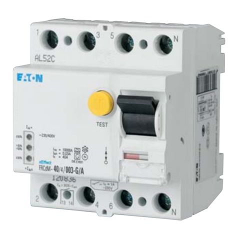
The Digitrip
RMS
31
0
Trip Unit is completely self
-
con
-
tained and when the circuit breakerisclosed, requiresno
external control power to operate its protectionsystems.
It operatesfrom current signal levels and control power
derivedthrough current sensors integrallymounted inthe
circuit breake
r.
Digitrip RMS310 Trip Units are suitablefor 50/60 Hz AC
applications only.
The Digitrip
RMS
31
0
Trip Unit is available in 4 different
types. Eachtrip unit contains a fixed long delaytime func
-
tion (adjusted by changing the rating plug), and may be
equippedwith a maximumof two phase and two ground
(time
-
current)adjustmentsto meet specific application
requirements.The types of adjustmentsavailable for
each model includethe following, which are illustrated in
Figures3.1 through 3.4.
Adjustment Refer to
Figure
1)
Short Delay Pick
-
up RESxxxxLS 3.1
2) Short Delay (Inst.) RESxxxxLSI 3.2
Pick-up1ShortDelay
Time
3) Short Delay Pick
-
up/ RESxxxxLSG 3.3
Ground Fault Pick
-
up/
Ground FaultTime
4)
Short Delay (Inst.) RESxxxxLSlG 3.4
Pick-up1ShortDelay
TimeIGround Fault
Time
1.2Testing
Test points (Figs. 3.1 through 3.4) are providedfor func
-
tionalfield testing of the trip unit when connectedto a test
kit (Catalog
No.
STK2).
2.0 UL LISTED DEVICES
The Digitrip
RMS
31
0
Trip Unit is listed in accordance
with UnderwritersLaboratories, Inc. Standard UL489,
under file E7819and satisfies the applicable require
-
ments of the International ElectrotechnicalCommission
(IEC) recommendationsfor moldedcase circuit breakers.
3.0
PRINCIPLE
OF
OPERATION
Inopen air at 40”C,an R
-
Framecircuit breakerwith a
Digitrip RMS310 Trip Unit installedwill carry continu
-
ously up to 1600,2000,or 2500 ampereswithout
exceedinga 50°Crise at the terminals.The calibrationof
the trip unit is insensitiveto ambient temperatures over a
range of
-
20”
to +55”C. However,the trip unit contains
thermal temperature protective circuitry that initiates a
trip operationfor self
-
protection
if
the internalambient
temperature at the printed circuit board (PCB) reaches
approximately 100°C.This may occur for open
-
air tem
-
peraturesabove 40°Cwith circuit breakercurrents near
full load.
For ambient conditions above 40°C and where the maxi
-
mum ampere rating plug has been installed,derating of
the circuit breakerframe should be considered to avoid
exceedinga safe terminal temperature operating range.
Consult Cutler
-
Hammerfor recommendations.
3.1
General
The Digitrip
RMS
31
0
Trip Unit providesa tripping signal
to the flux transfer shunt trip when current and time delay
settings are exceeded. This is accomplished by employ
-
ing the Cutler
-
Hammercustom designed integratedcir
-
cuit SyreTMchip, which includesa microcomputerto
perform its numeric and logicfunctions.
Inthe Digitrip
RMS
31
0
Trip Unit,all requiredsensingand
tripping powerto operate its protectionfunction isderived
from the current sensors in the circuit breaker.The sec
-
ondary currents from these sensors providethe correct
input informationfor the protectionfunctions, as well as
tripping power, whenever the circuit breaker is carrying
current.These current signals develop voltages across
the appropriate calibrating resistors.
The microcomputer,in cyclic fashion, repeatedlyscans
the voltage values across each calibrating resistor and
entersthese values into memory.These data are usedto
calculatetrue
RMS
currentvalues, which are then
repeatedlycomparedwith the protectionfunctionsettings
and other operatingdata stored in memory.The software
programthen determines whether to initiate protection
functions, includingtripping the breakerthrough the flux
transfer shunt trip device inthe circuit breaker.
A green status light indicates the operational status of
the trip unit. If the load current through the circuit break-
of a properly functioning trip unit. If the status light is not
blinking, the current through the breaker may be less
than 20% of the maximum current rating of the trip unit
If the current exceeds 20% and the status light is not
blinking, use the STK2 test kit to investigate. IF THE
STATUS LIGHT IS ON STEADY, IT INDICATES A
Effective February 2006
I.L. 29C883E
Page 2
TRIP IS PENDING.
er exceeds approximately 20% of the maximum current
rating of the tirp unit, the status light will blink on and off
once each second. A blinking status light is an indication
Courtesy of NationalSwitchgear.com
