manuals.online logo
Brands
  1. Home
  2. •
  3. Brands
  4. •
  5. Eaton
  6. •
  7. Controllers
  8. •
  9. Eaton A200 Manual

Eaton A200 Manual

Instruction Leaet IL16958 Effective May 2011
Supersedes August 1992
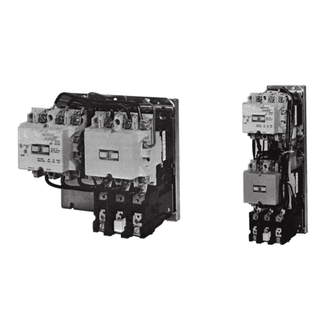
A200 Size 00, 0, 1 3 Pole Motor Controller
THE CONTROLLER
The A200 motor controller, when wired as shown in Figure
6 or 7, will operate as a full voltage starter and will give
protection against overload, but not against short circuit
currents, when wired and provided with overload relay (OlR)
heaters as listed in heater selection tables or when used
with any means of inherent protection activated by motor
temperature.
The controller should be protected against short circuits by
providing branch circuit protection not to exceed the maximum
protective device ratings listed in Table II.
This industrial type control is designed to be installed, perated,
and maintained by adequately trained work-men. These
instructions do not cover all details, variations, or combinations
of the equipment, its storage, delivery, installation, check out,
safe operation, or maintenance. Care must be exercised to
comply with local, state, and national regulations, as well as
safety practices, for this class of equipment.
AUXILIARY CONTACTS - TYPE J
One normally-open pole adjacent to the power poles is
supplied as the holding circuit auxiliary. A maximum of four
Type J auxiliary units can be installed in the recesses of
each contactor. These may be mounted with the terminals
in line with the power poles or may be mounted with the
terminals in a right angle relationship to the power poles.
Auxiliary contacts mount by means of a spring clip and
retainer screw.
Figure 1. Size 1 A 200 Controller
Figure 2. Dimension Drawings (Dim. in inches)
2
Instruction Leaet IL16958
Effective May 2011
For A200 Size 00, 0, 1
3 Pole Motor Controller
EATON CORPORATION www.eaton.com
AUXILIARY CONTACTS -TYPE J (cont.)
To remove the unit rotate the retainer screw several times
(counterclockwise) and then slide the auxiliary contact unit out of
the recess.
TYPE B OVERLOAD RELAY (See Figure 3)
This A200 motor controller is usually equipped with a Type B block
type ambient compensated overload relay (with gray reset rod). The
controller can also be supplied with a non-ambient compensated
overload relay (with red reset rod). The relay is of the bimetal
actuated type equipped with a normally-closed control contact. An
optional isolated normally-open control circuit is available for field
mounting. When the overload relay trips, a yellow dot will appear
flush with the molded surface below the reset rod. Resetting the
relay returns this indicator to its normal concealed position.
HEATERS
Heaters are not included with the motor controller and must be
ordered separately per the heater selection table and the information
listed below. When installing heaters be sure that connecting
surfaces are clean and heaters are attached securely to the relay
in the proper location with the screw provided. The trip rating of a
heater in a 40°C Ambient is 125% of the minimum fullload current
shown in Table II. When tested at 600 percent of its trip rating, the
relay will trip in 20 seconds or less.
TYPE A OVERLOAD RELAY (See Figure 4)
The A200 motor controller can be equipped with a Type A block type
non-ambient compensated overload relay (unmarked and with red
reset rod) or with a block type temperature compensated overload
relay (marked “ambient compensated” and with gray reset rod). The
relay is of the bimetal actuated type equipped with trip indicator, trip
adjustment covering ± 15% of rating and a normally-closed control
contact. It may be operated with either hand or automatic reset.
Reset operation is determined by the position of the plate on the
load side of the overload base. Position the reset plate away from
the panel to set the “hand” position. Loosen the locking screw,
move the reset plate toward the panel, and retighten the screw to
set the “auto” position.
Automatic reset should not be used with 2-wire control circuits
where automatic starting of the motor may be hazardous.
Figure 3. Type B overload Relay
Figure 4. Type A Block Overload Relay
3
Instruction Leaet IL16958
Effective May 2011
For A200 Size 00, 0, 1
3 Pole Motor Controller
EATON CORPORATION www.eaton.com
Heaters should be selected on the basis of the actual full load
current and service factor as shown on the motor nameplate or in
the manufacturer’s published literature. When the service factor of
the motor is 1.15 to 1.25, select heaters from the heater application
table. If the service factor of the motor is 1.0, or there is no service
factor shown, or a maximum of 115% protection is desired, select
one size smaller heater than indicated. When motor and overload
relay are in different ambients and when using non-compensated
overload relays, select heaters from the table using adjusted motor
currents as follows: decrease rated motor current 1% for each °C
motor ambient exceeds controller ambient. Increase rated motor
current 1% for each °C controller ambient exceeds motor ambient.
The conductors attached to the terminals of an overload relay act as
a heat sink and are a consideration in establishing the current rating
of each heater element. To prevent nuisance tripping, which will
occur if undersized conductors are used, select the wire size as if
the conductors had an insulation temperature rating of 75°C, even if
the conductors actually used have a temperature rating higher than
75°C.
Protect the heater and starter against short circuits by providing
branch circuit protection in accordance with the National Electrical
Code.
WARNING:
TO PROVIDE CONTINUED PROTECTION AGAINST FIRE AND SHOCK HAZ-
ARD, THE COMPLETE OVERLOAD RELAY MUST BE REPLACED IF BURNOUT
OF A CURRENT ELEMENT OCCURS. SEE TABLE I.
4
Instruction Leaet IL16958
Effective May 2011
For A200 Size 00, 0, 1
3 Pole Motor Controller
EATON CORPORATION www.eaton.com
COIL
The A200 motor controller is available with a single or dual voltage
coil. When equipped with a single voltage coil. the contactor is wired
as shown in Figures 6 and 7. A connection diagram for a dual voltage
coil is shown in Figure 5. When supplied with a dual voltage coil. the
motor controller is normally wired for the higher voltage connection.
The wiring may be changed to the lower voltage connection by
removing and reconnecting the jumpers as illustrated below.
AC COIL DATA, SIZE 00, 0 AND 1
(TYPICAL VALUES)
Inrush Sealed sealed Pickup Droput
VA VA Watts (Time in milliseconds)
160 25 7.8 16-24 12-16
RAPLACEMENT COIL: ORDER BY PART NUMBER,
VOLTATE, AND FREQUENCY
Figure 5. Dual Voltage Coil Connections
Figure 6. Connection Diagram (Type B Overload)
Figure 7. Connection Diagram (Type A Overload)
5
Instruction Leaet IL16958
Effective May 2011
For A200 Size 00, 0, 1
3 Pole Motor Controller
EATON CORPORATION www.eaton.com
Figure 8. Control Station Connection Diagram
SHORT - CIRCUIT WITHSTAND
This motor controller is suitable for use on a circuit capable of
delivering not more than the current (rms symmetrical amperes)
shown below in circuits rated not more than the voltage shown
below (Table V).
Eaton Corporation
Electrical Sector
1111 Superior Ave.
Cleveland, OH 44114
United States
877-ETN-CARE (877-386-2273)
Eaton.com
© 2011 Eaton Corporation
All Rights Reserved
Publication No. IL16958 / 001
May 2011
Eaton is a registered trademark of Eaton
Corporation.
All other trademarks are property of their
respective owners.
Instruction Leaet IL16958
Effective May 2011
A200 Size 00, 0, 1
3 Pole Motor Controller
MAINTENANCE - First Turn Off Power
To Inspect Contacts Refer to Figure 9. Loosen the two arc box
assembly screws (7) located immediately above and below the
nameplate and remove the arc box (8). Contacts (5) are visible.
Retighten the screws per Table VI.
To Replace Contacts
After removing the arc box and with replacement contacts at hand,
compress the overtravel spring (12) and remove the moving contact
(5) from the crossbar (6). Disconnect any power cables. Remove the
retaining screws (11) and lift out the stationary contact assembly
(14).
To replace contacts, reverse the above procedure, making sure that
stationary contacts are secure (see Table VI), moving contacts are
free to move, overtravel springs are seated and the crossbar moves
freely when the arc box is in position.
The silver cadmium oxide contact buttons need NO dressing or
lubricant throughout their life. Important - Replace all contacts and
springs as a group to avoid misalignment.
To Replace The Coil
Refer to Figure 9. Loosen the assembly screws (10) located to the
immediate top and bottom of the arc box.
Remove connector straps to the overload relay. Pull the loosened
upper base structure (9) forward. Pull the· coil (1) from the upper
base, plug in a new coil, replace the upper base structure and
check the auxiliary contacts for secureness when repositioning the
upper base. Tighten the assembly screws and the connector straps
screws. Refer to Table VI.
Magnet - Armature Assembly
Self alignment and permanent air gap features of the magnet
armature make replacement unnecessary. Mating pole face surfaces
should be kept clean.
Arc box must be in place when the contactor interrupts a circuit.
Figure 9. Size 1 Contator (Exploded View)

Other Eaton Controllers manuals

Eaton SVX9000 Series User manual

Eaton

Eaton SVX9000 Series User manual

Eaton xComfort CAAE-01/01 User manual

Eaton

Eaton xComfort CAAE-01/01 User manual

Eaton MMX11 Series User manual

Eaton

Eaton MMX11 Series User manual

Eaton FC18 User manual

Eaton

Eaton FC18 User manual

Eaton XV-152 Series Manual

Eaton

Eaton XV-152 Series Manual

Eaton ATC-600 Programming manual

Eaton

Eaton ATC-600 Programming manual

Eaton COOPER POWER SERIES Manual

Eaton

Eaton COOPER POWER SERIES Manual

Eaton Greengate PPS-5 User manual

Eaton

Eaton Greengate PPS-5 User manual

Eaton PKE-SWD-32 User manual

Eaton

Eaton PKE-SWD-32 User manual

Eaton xComfort CAAE Series Manual

Eaton

Eaton xComfort CAAE Series Manual
Eaton CRCA-00/08 Manual

Eaton

Eaton CRCA-00/08 Manual

Eaton A210 Manual

Eaton

Eaton A210 Manual

Eaton A200 Manual

Eaton

Eaton A200 Manual

Eaton COOPER POWER SERIES User manual

Eaton

Eaton COOPER POWER SERIES User manual

Eaton PowerXL DE1 series User manual

Eaton

Eaton PowerXL DE1 series User manual

Eaton Cuttler-Hammer Digitrip 1150V User manual

Eaton

Eaton Cuttler-Hammer Digitrip 1150V User manual

Eaton Crouse-Hinds Flex-Station EDS Series Setup guide

Eaton

Eaton Crouse-Hinds Flex-Station EDS Series Setup guide

Eaton ELCM Series User manual

Eaton

Eaton ELCM Series User manual

Eaton COOPER POWER SERIES Service manual

Eaton

Eaton COOPER POWER SERIES Service manual

Eaton ER9.3-10 User manual

Eaton

Eaton ER9.3-10 User manual

Eaton A201 Manual

Eaton

Eaton A201 Manual

Eaton DS7 Series Manual

Eaton

Eaton DS7 Series Manual

Eaton Vikers V200 Series User manual

Eaton

Eaton Vikers V200 Series User manual

Eaton A210 Manual

Eaton

Eaton A210 Manual

Popular Controllers manuals by other brands

Baker Hughes Masoneilan SVI II ESD quick start guide

Baker Hughes

Baker Hughes Masoneilan SVI II ESD quick start guide

Mitsubishi FX2N-64CL-M user manual

Mitsubishi

Mitsubishi FX2N-64CL-M user manual

London Electronics INT2-AH manual

London Electronics

London Electronics INT2-AH manual

KBi KAPower MKSM Series Operation manual

KBi

KBi KAPower MKSM Series Operation manual

Danfoss AK-CC55 user guide

Danfoss

Danfoss AK-CC55 user guide

ComAp InteliNano NT MRS Fast user's guide

ComAp

ComAp InteliNano NT MRS Fast user's guide

iSMA CONTROLLI iSMA-B-AAC20 user manual

iSMA CONTROLLI

iSMA CONTROLLI iSMA-B-AAC20 user manual

Danfoss A377.1 Mounting guide

Danfoss

Danfoss A377.1 Mounting guide

Nibe RMU S40 Installer manual

Nibe

Nibe RMU S40 Installer manual

Festo CPX-FEC Brief description

Festo

Festo CPX-FEC Brief description

Grundfos DPC 1-3 Installation & operating instruction

Grundfos

Grundfos DPC 1-3 Installation & operating instruction

Atmel ATMEGA256RFR2 Xplained Pro manual

Atmel

Atmel ATMEGA256RFR2 Xplained Pro manual

sauter AVF124 Fitting instructions

sauter

sauter AVF124 Fitting instructions

Siemens SIKOSTART 3RW35 Instruction guide

Siemens

Siemens SIKOSTART 3RW35 Instruction guide

IDK SWC-2000 manual

IDK

IDK SWC-2000 manual

Moeller DEX-KEY-10 installation instructions

Moeller

Moeller DEX-KEY-10 installation instructions

MDT Technologies JAL-01UP.02 Technical manual

MDT Technologies

MDT Technologies JAL-01UP.02 Technical manual

Samson 3277 Mounting and operating instructions

Samson

Samson 3277 Mounting and operating instructions

manuals.online logo
manuals.online logoBrands
  • About & Mission
  • Contact us
  • Privacy Policy
  • Terms and Conditions

Copyright 2025 Manuals.Online. All Rights Reserved.