Page 9
ATS-00_EN
ENGLISH
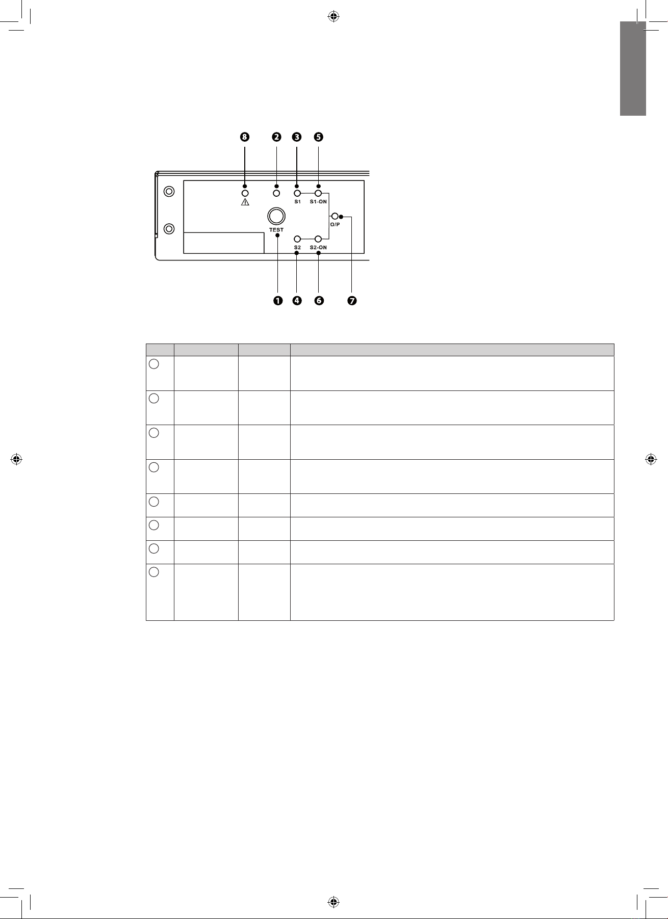
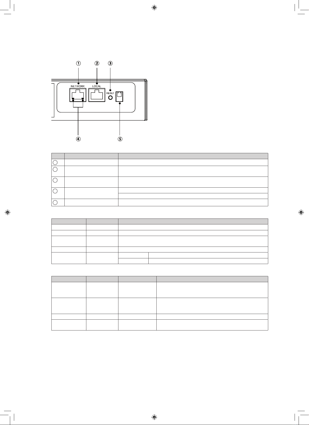
5.1 User interface
The following table shows the indicator status and description:
N° Indicator Status Description
1Test button -Use this button to test the Eaton ATS. Press this button, the Eaton ATS
will transfer to the 2nd source for 1 minute and then transfer back to
original preferred source.
2Test LED Green If you press the test button, the Eaton ATS will be under test conditions
and theTest LED will flash (on: 0.5s; off: 0.5s). In normal operation, this
LED will be off.
3S1 LED Green This LED indicates the condition of input source 1. If the input source 1
is within acceptable range, this LED will light up as green. If the input
source 1 is out of acceptable range, this LED will be off.
4S2 LED Green This LED indicates the condition of input source 2. If the input source 2
is within acceptable range, this LED will light up as green. If the input
source 2 is out of acceptable range, this LED will be off.
5S1_ON LED Green If the Eaton ATS uses input source 1 to supply power to the output, this
LED will light up as green. If not, this LED will be off.
6S2_ON LED Green If the Eaton ATS uses input source 2 to supply power to the output, this
LED will light up as green. If not, this LED will be off.
7O/P LED Green This LED indicates the output condition (voltage is > 60Vac). If there is
output, this LED will light up as green. If not, this LED will be off.
8Fault LED Red If the Eaton ATS has any internal fault, this LED will light up as red. If
the Eaton ATS has any environmental fault, this LED will flash (ON: 0.5s;
OFF: 0.5s). Via the "NETWORK" port, fault messages will be sent to a
connected PC. From the PC, you can see error codes as follows in the
troubleshooting in page 11 .
5. Operation