Echo CGSL01AF1 User manual

CGSL01AF1
CGSL11AF1
CGSL21AF1
Charging Station
Operator’s Manual
©2019 ECHO Incorporated. All Rights Reserved.
X7507850000
REVISED 1/11/19
EN
ENGLISH

i
Contents
Chapter: 1 User Information . . . . . . . . . . . . . . . . . . . . . . . . . . . . . . 1
FCC Declarations . . . . . . . . . . . . . . . . . . . . . . . . . . . . . . . 1
Image Description . . . . . . . . . . . . . . . . . . . . . . . . . . . . . . . 1
California Proposition 65 . . . . . . . . . . . . . . . . . . . . . . . . . . . 1
Chapter: 2 Safety Symbols . . . . . . . . . . . . . . . . . . . . . . . . . . . . . . . . 2
Chapter: 3 Safety Instructions . . . . . . . . . . . . . . . . . . . . . . . . . . . . . . 3
Chapter: 4 Charging Station Model Descriptions, Specifications, and Dimensions . 4
Model Descriptions . . . . . . . . . . . . . . . . . . . . . . . . . . . . . . 4
Specifications (all models) . . . . . . . . . . . . . . . . . . . . . . . . . . 4
Dimensions . . . . . . . . . . . . . . . . . . . . . . . . . . . . . . . . . . 5
Chapter: 5 Charging Station Components . . . . . . . . . . . . . . . . . . . . . . . 7
Chapter: 6 Charging Station Installation Requirements . . . . . . . . . . . . . . . . 8
Required Tools . . . . . . . . . . . . . . . . . . . . . . . . . . . . . . . . 8
AC Power Supply Wiring . . . . . . . . . . . . . . . . . . . . . . . . . . . 8
Installation Offsets . . . . . . . . . . . . . . . . . . . . . . . . . . . . . . 9
Chapter: 7 Charging Station Installation Procedure . . . . . . . . . . . . . . . . . 10
Station Loop, Field Zone 1, and Field Zone 2 Charging Stations . . . . . .10
Chapter: 8 Alignment to Robot . . . . . . . . . . . . . . . . . . . . . . . . . . . . 16
Alignment Instructions . . . . . . . . . . . . . . . . . . . . . . . . . . . .16
Chapter: 9 Operation . . . . . . . . . . . . . . . . . . . . . . . . . . . . . . . . . . 20
Power Switch . . . . . . . . . . . . . . . . . . . . . . . . . . . . . . . . .20
LED Indicators . . . . . . . . . . . . . . . . . . . . . . . . . . . . . . . . .20

ii
Chapter: 10 Maintenance Procedures . . . . . . . . . . . . . . . . . . . . . . . . . 22
General Inspection and Cleaning . . . . . . . . . . . . . . . . . . . . . .22
Cold Weather Storage (as installed) . . . . . . . . . . . . . . . . . . . . .22
Cold Weather Storage or Moving (removed from installation) . . . . . .22
Chapter: 11 BDR100 Timer Accessory Kit . . . . . . . . . . . . . . . . . . . . . . . 25
Components . . . . . . . . . . . . . . . . . . . . . . . . . . . . . . . . . .25
Required Tools . . . . . . . . . . . . . . . . . . . . . . . . . . . . . . . .26
Installation . . . . . . . . . . . . . . . . . . . . . . . . . . . . . . . . . . .26
Timer Cable Assembly to Charging Station . . . . . . . . . . . . . . . . .29

1
FCC DECLARATIONS
CHAPTER 1 USER INFORMATION
1. User Information
©2019 ECHO Incorporated.
All Rights Reserved.
This publication or parts thereof may not be reproduced in any form, by any method, for any purpose.
ECHO has taken reasonable care in compiling this document, however ECHO accepts no liability whatso‐
ever for any error or omission in the information contained herein and gives no other warranty or under‐
taking as to its accuracy.
ECHO can accept no responsibility for damages, resulting from the use of the operating software. In addi‐
tion, we refer to the conditions of use specified in the license contract. ECHO reserves the right to amend
this document at any time without prior notice.
ECHO and its affiliates are not liable for damages or losses related to such security breaches, any unau‐
thorized access, interference, intrusion, leakage and/or theft of data or information.
1.1. FCC Declarations
This equipment has been tested and found to comply with the limits/or a Class A digital device, pursuant
to part 15 of the FCC Rules. These limits are designed to provide reasonable protection against harmful
interference when the equipment is operated in a commercial environment. This equipment generates,
uses, and can radiate radio frequency energy and, if not installed and used in accordance with the
instruction manual, may cause harmful interference to radio communications. Operation of this equip‐
ment in a residential area is likely to cause harmful interference in which case the user will be required
to correct the interference at their own expense.
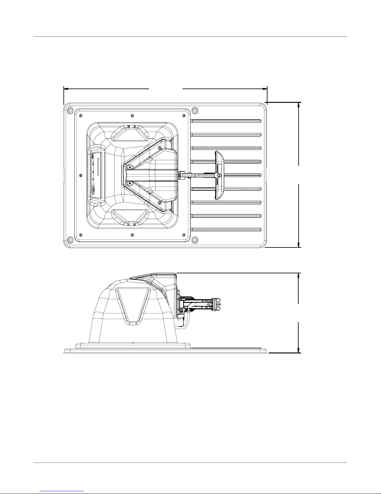
1.2. Image Description
All images in this document show the mower configuration for the charging station unless otherwise
noted.
1.3. California Proposition 65
Cancer and Reproductive Harm
www.P65Warnings.ca.gov

2
CHAPTER 2 SAFETY SYMBOLS
2. Safety Symbols
Throughout this manual and on the product itself, you will find safety alerts and helpful, informational
messages preceded by symbols or key words. The following is an explanation of those symbols and key
words and what they mean to you.
Circle and Slash Symbol: This symbol means the specific action shown is prohibited. Ignoring this symbol
can result in damage to property and serious or fatal injury.
The safety alert symbol accompanied by the word “DANGER” calls attention to an act or condition which
WILL lead to serious personal injury or death if not avoided.
The safety alert symbol accompanied by the word “WARNING” calls attention to an act or condition
which CAN lead to serious personal injury or death if not avoided.
The safety alert symbol accompanied by the word “CAUTION” calls attention to an act or condition which
may lead to minor or moderate personal injury if not avoided.
The enclosed message provides information necessary for the protection of the unit.

3
CHAPTER 3 SAFETY INSTRUCTIONS
3. Safety Instructions
IMPORTANT: It is recommended to have the installation performed by a licensed electrician.
1) SAVE THESE INSTRUCTIONS – This manual contains important safety and operating instructions for
charging station models CGSL01AF1, CGSL11AF1, and CGSL21AF1.
2) Before using, read all instructions and cautionary markings on the charging station and on the
robot.
3) CAUTION – To reduce risk of injury, only charge the robot with this charging station.
HAZARDOUS VOLTAGE
Risk of fire and burn.
• To reduce the risk of fire or burn, use only on circuits provided with 15 A branch‐circuit protection in ac‐
cordance with the National Electrical Code, ANSI/NFPA 70.
•De‐energize AC power before performing work to, or near, the charging station.
• Follow all lock‐out and tag‐out procedures.
• Perform installation or maintenance in dry conditions
• Do not allow any conductive materials to touch the guarded charger output contacts.
• Do not use a charging station which has been physically damaged.

4
MODEL DESCRIPTIONS
CHAPTER 4CHARGING STATION MODEL DESCRIPTIONS, SPECIFICATIONS, AND DIMENSIONS
4. Charging Station Model Descriptions, Specifica‐
tions, and Dimensions
4.1. Model Descriptions
4.2. Specifications (all models)
Model Description
CGSL01AF1 Charger with Station Loop peripheral wire only.
CGSL11AF1 Charger with Station Loop peripheral wire and
one Field Zone peripheral wire.
CGSL21AF1 Charger with Station Loop peripheral wire and
two Field Zone peripheral wires.
Operating Temperature 0 to 50° C
Input 120 VAC ‐60 Hz (360 W maximum)
Charge Outputs 32 VDC (320 W maximum)
Output Circuits Class 2

5
DIMENSIONS
CHAPTER 4CHARGING STATION MODEL DESCRIPTIONS, SPECIFICATIONS, AND DIMENSIONS
4.3. Dimensions
Mower Configuration Shown (A‐top view, B‐side view):
A
B
39.1 in.
(993 mm)
25.4 in.
(646 mm)
14.0 in.
(356 mm)

6
DIMENSIONS
CHAPTER 4CHARGING STATION MODEL DESCRIPTIONS, SPECIFICATIONS, AND DIMENSIONS
Range Picker Configuration Shown (A‐top view, B‐side view):
A
B
39.1 in.
(993 mm)
25.4 in.
(646 mm)
14.0 in.
(356 mm)

7
CHAPTER 5 CHARGING STATION COMPONENTS
5. Charging Station Components
1 ‐Enclosure top 6 ‐Serial number location
2 ‐Dust cover 7 ‐T‐27 Torx® driver
3 ‐Charging arm 8‐Conduit connector
4 ‐Base 9 ‐Tie strap (13X)
5 ‐Input panel – Caution label
8
2
6
1
3
4
5
7 9

8
REQUIRED TOOLS
CHAPTER 6 CHARGING STATION INSTALLATION REQUIREMENTS
6. Charging Station Installation Requirements
Identify the location of AC power, Station Loop, Field Zone 1, and Field Zone 2 peripheral wires before
installing the charging station. Install the charging station on flat ground where flooding or water accu‐
mulation will not occur. Do not bend, warp, or crack the base during installation.
6.1. Required Tools
6.2. AC Power Supply Wiring
Use 14 AWG electrical wire and ½ in. liquid‐tight electrical conduit for AC power into the charging station.
NOTE: Wire and conduit are not included with the charging station.
8 mm Socket Driver Hammer
3 mm Flat‐Blade Screwdriver Slip‐Joint Pliers
#1 Phillips Screwdriver T‐27 Torx® Driver
Adjustable Wrench 7/8 in. Drill Bit
Wire Strippers Fasteners and additional cord grip for Timer Box
Accessory Kit (not included)
Tape Measure
1 ‐Line (black) 3 ‐Neutral (white)
2 ‐Ground (green) 4 ‐Liquid‐tight electrical conduit
1
11
21
3
4

9
INSTALLATION OFFSETS
CHAPTER 6 CHARGING STATION INSTALLATION REQUIREMENTS
6.3. Installation Offsets
Install the charging station on flat ground whenever possible. If the entire field is on a slope, install the
charging station on a flat portion at the top. The robot has no brake when it is in charge mode. The robot
can slide away from the charging contacts if the longitudinal slope (by which the robot enters the
charging station) is greater than zero degrees (0°).
!
!

10
STATION LOOP, FIELD ZONE 1, AND FIELD ZONE 2 CHARGING STATIONS
CHAPTER 7 CHARGING STATION INSTALLATION PROCEDURE
7. Charging Station Installation Procedure
IMPORTANT: Do not bend, warp, or crack the base during installation.
Follow all safety instructions. See Safety Instructions.
This procedure is a basic overview of the charging station installation. Each installation varies by applica‐
tion. Consult your dealer for specific questions regarding installation.
7.1. Station Loop, Field Zone 1, and Field Zone 2 Charging Stations
1) Clear debris, cut grass, or vegetation from the installation location.
2) Remove the charging station from its packaging. Lift the charging station from the base, do not lift
it from the charging arm.
3) Remove the M5 nuts (8X) from the base of the enclosure top and save for reassembly.
4) Range Picker configuration only: Carefully lift and rotate the enclosure top 180°. Align the holes in
the enclosure top with the holes in the base. Place the enclosure top onto the base (ensure no wires
are pulled or pinched).

11
STATION LOOP, FIELD ZONE 1, AND FIELD ZONE 2 CHARGING STATIONS
CHAPTER 7 CHARGING STATION INSTALLATION PROCEDURE
5) Move the charging station to the final installation location. Place the front of the enclosure top
26.4 in. (670 mm) from the Station Loop, Field Zone 1, and Field Zone 2 peripheral wires.
6) Route the Station Loop, Field Zone 1, and Field Zone 2 peripheral wires under the base and up
through a cord grip. Allow a minimum length of 15.7 in. (400 mm) of each peripheral wire inside the
enclosure top. Hand‐tighten the cord grips. Provide excess wire under the base for future reposi‐
tioning.
1 ‐Front of enclosure top 3‐Field Zone 1 peripheral wire
2 ‐Station Loop peripheral wire 4‐Field Zone 2 peripheral wire
1 ‐Peripheral wire
28.3 in.
(720 mm)
143
2
15.7 in.
(400 mm)
2
1

12
STATION LOOP, FIELD ZONE 1, AND FIELD ZONE 2 CHARGING STATIONS
CHAPTER 7 CHARGING STATION INSTALLATION PROCEDURE
7) Remove 0.3 in. (8 mm) of insulation from the end of each peripheral wire.
8) Loosen the surge protector(s) terminal screws, insert the stripped ends of the peripheral wires into
the surge protector(s) at the locations shown, securely tighten the terminal screws.
9) Use an adjustable wrench or slip‐joint pliers to securely tighten the cord grips. This will secure the
peripheral wires to the base, and create a water‐tight seal.
10) Pull the 14 AWG AC wires through the ½ in. liquid‐tight conduit. Assemble conduit connector,
fitting, and seal, to the liquid‐tight conduit. Place the conduit connector into the input panel. Place
2 ‐Cord grip
1 ‐Peripheral wire
2 ‐Surge protectors
3‐Peripheral wire locations
1
1
2
3
2

13
STATION LOOP, FIELD ZONE 1, AND FIELD ZONE 2 CHARGING STATIONS
CHAPTER 7 CHARGING STATION INSTALLATION PROCEDURE
the nut on the inside of the panel and tighten it onto the fitting. Allow 35.4 in. (400 mm) of wire on
the inside of the enclosure top.
11) Remove 0.4 in. (11 mm) of insulation from the end of each wire.
12) Insert a flat‐blade screwdriver into the small terminal block opening(s) to open the spring contact.
Install the 14 AWG AC wires (neutral‐white, line‐black, ground‐green) into their corresponding
large terminal block openings. Install one wire per terminal block opening. The stripped ends of the
1 ‐14 AWG AC wires 4 ‐Seal
2 ‐Liquid‐tight conduit 5 ‐Input panel
3‐Conduit connector 6 ‐Nut
35.4 in.
(400 mm)
3
4
1
2
3
5
6
3

14
STATION LOOP, FIELD ZONE 1, AND FIELD ZONE 2 CHARGING STATIONS
CHAPTER 7 CHARGING STATION INSTALLATION PROCEDURE
wire (or stray strands of wire) must remain on the inside of the terminal block. Remove the screw‐
driver. Gently pull each wire to verify a secure connection.
13) Align the holes in the enclosure top with the holes in base. Place the enclosure top onto the base.
Ensure no wires a pulled or pinched. Assemble and securely tighten the M5 nuts (8X).
1 ‐Small terminal block openings
2 ‐14 AWG AC wires
3 ‐Large terminal block openings
2
1
3

15
STATION LOOP, FIELD ZONE 1, AND FIELD ZONE 2 CHARGING STATIONS
CHAPTER 7 CHARGING STATION INSTALLATION PROCEDURE
14) Mower Configuration Only: Remove underground hazards below the charging station. Use a
hammer to install the four landscaping spikes to secure the base to the ground.
15) Range Picker Configuration Only: Use the appropriate size and type of anchor to secure the
charging station to the foundation of the ball collection system.

16
ALIGNMENT INSTRUCTIONS
CHAPTER 8 ALIGNMENT TO ROBOT
8. Alignment to Robot
The charging arm will move to allow for correct alignment to the robot.
•A‐Mower Configuration
•B‐Range Picker Configuration
8.1. Alignment Instructions
1) Remove the landscaping spikes or anchors from the base of the charging station.
2) Push the robot to the charging station along the Station Loop peripheral wire.
A
B

17
ALIGNMENT INSTRUCTIONS
CHAPTER 8 ALIGNMENT TO ROBOT
3) Place the robot on the charging station, do not allow charging arm to contact the robot. Visually
inspect the alignment of the charging arm to the charging panel on the robot.
4) Move the charging arm assembly up or down as required. Use a T‐27 Torx®Driver to loosen the
mounting screws (4X) on the charging arm mounting plate.
1 ‐Charging arm
2 ‐Charging panel
1 ‐Mounting screws
2 ‐Charging arm mounting plate
1
2
1
2
2
1
1
This manual suits for next models
2
Table of contents
Other Echo Batteries Charger manuals