manuals.online logo
Brands
  1. Home
  2. •
  3. Brands
  4. •
  5. Ecoflam
  6. •
  7. Burner
  8. •
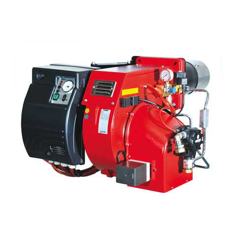
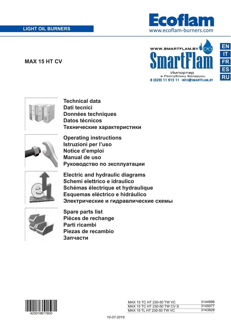
  9. Ecoflam MULTICALOR 300.1 PR Series User manual

Ecoflam MULTICALOR 300.1 PR Series User manual

This manual suits for next models

19

Other Ecoflam Burner manuals

Ecoflam MAX P 45 AB User manual

Ecoflam

Ecoflam MAX P 45 AB User manual

Ecoflam MULTICALOR 500.1 PRE Series User manual

Ecoflam

Ecoflam MULTICALOR 500.1 PRE Series User manual

Ecoflam BLU 1700.1 PRE Series User manual

Ecoflam

Ecoflam BLU 1700.1 PRE Series User manual

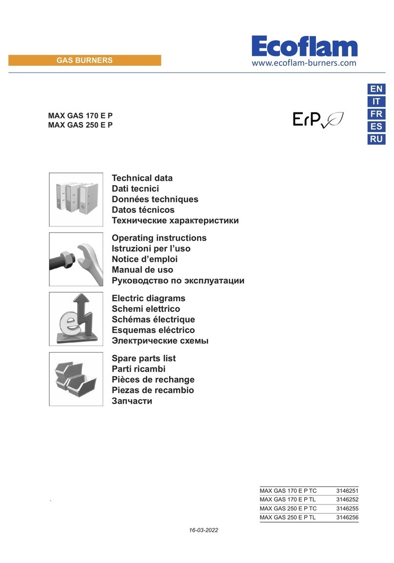
Ecoflam MAX GAS 170 E P User manual

Ecoflam

Ecoflam MAX GAS 170 E P User manual

Ecoflam BLU 500.1 PR User manual

Ecoflam

Ecoflam BLU 500.1 PR User manual

Ecoflam MAIOR P 15 AB User manual

Ecoflam

Ecoflam MAIOR P 15 AB User manual

Ecoflam Multicalor 170.1 User manual

Ecoflam

Ecoflam Multicalor 170.1 User manual

Ecoflam MAX GAS 350 PR User manual

Ecoflam

Ecoflam MAX GAS 350 PR User manual

Ecoflam BLU TS 5000.1 PR HT User manual

Ecoflam

Ecoflam BLU TS 5000.1 PR HT User manual

Ecoflam Minor 15 B-J/F 115 User manual

Ecoflam

Ecoflam Minor 15 B-J/F 115 User manual

Ecoflam BLU 1500.1 PR User manual

Ecoflam

Ecoflam BLU 1500.1 PR User manual

Ecoflam Multicalor 45 User manual

Ecoflam

Ecoflam Multicalor 45 User manual

Ecoflam Multicalor 170.1 PRE Series User manual

Ecoflam

Ecoflam Multicalor 170.1 PRE Series User manual

Ecoflam BLU TS 3000.1 PRE HT User manual

Ecoflam

Ecoflam BLU TS 3000.1 PRE HT User manual

Ecoflam MAX 15 User manual

Ecoflam

Ecoflam MAX 15 User manual

Ecoflam MAX 1 Low NOx User manual

Ecoflam

Ecoflam MAX 1 Low NOx User manual

Ecoflam DUAL 1 User manual

Ecoflam

Ecoflam DUAL 1 User manual

Ecoflam MAX GAS 350 PAB TC User manual

Ecoflam

Ecoflam MAX GAS 350 PAB TC User manual

Ecoflam MAX 1R LOW NOx User manual

Ecoflam

Ecoflam MAX 1R LOW NOx User manual

Ecoflam Multicalor 500.1 PR User manual

Ecoflam

Ecoflam Multicalor 500.1 PR User manual

Ecoflam ECOJET 5 User manual

Ecoflam

Ecoflam ECOJET 5 User manual

Ecoflam MAX GAS 350 PR User manual

Ecoflam

Ecoflam MAX GAS 350 PR User manual

Ecoflam MAIOR P 700.1 PRE User manual

Ecoflam

Ecoflam MAIOR P 700.1 PRE User manual

Ecoflam Maior P45 PR User manual

Ecoflam

Ecoflam Maior P45 PR User manual

Popular Burner manuals by other brands

Riello RLS 160/EV Installation, use and maintenance instructions

Riello

Riello RLS 160/EV Installation, use and maintenance instructions

Riello RS 28/M Installation, use and maintenance instructions

Riello

Riello RS 28/M Installation, use and maintenance instructions

True Induction TI4B user guide

True Induction

True Induction TI4B user guide

Riello RG1RKD Installation, use and maintenance instructions

Riello

Riello RG1RKD Installation, use and maintenance instructions

Weishaupt WG20 Series manual

Weishaupt

Weishaupt WG20 Series manual

Carolina Cooker M116672 owner's guide

Carolina Cooker

Carolina Cooker M116672 owner's guide

Riello RX 500 S/PV Modulating operation

Riello

Riello RX 500 S/PV Modulating operation

Unigas HTP2000 installation manual

Unigas

Unigas HTP2000 installation manual

baltur BT 250 DSG 4T manual

baltur

baltur BT 250 DSG 4T manual

muenkel design round burner Operating and installation instructions

muenkel design

muenkel design round burner Operating and installation instructions

baltur BT 14 DSGW Instruction

baltur

baltur BT 14 DSGW Instruction

artisan Art-SB1 Care & use manual

artisan

artisan Art-SB1 Care & use manual

AESYS TurboFire II Installation, operation and maintenance manual

AESYS

AESYS TurboFire II Installation, operation and maintenance manual

IKEA GRILLSKÄR manual

IKEA

IKEA GRILLSKÄR manual

baltur TBL 1000 ME Instruction manual for installation, use and maintenance

baltur

baltur TBL 1000 ME Instruction manual for installation, use and maintenance

Riello Burners P 200 P/G Installation, use and maintenance instructions

Riello Burners

Riello Burners P 200 P/G Installation, use and maintenance instructions

WLD-TEC powerjet instruction manual

WLD-TEC

WLD-TEC powerjet instruction manual

Riello RDB 3.2 BX 32/50 Installation, use and maintenance instructions

Riello

Riello RDB 3.2 BX 32/50 Installation, use and maintenance instructions

manuals.online logo
manuals.online logoBrands
  • About & Mission
  • Contact us
  • Privacy Policy
  • Terms and Conditions

Copyright 2025 Manuals.Online. All Rights Reserved.

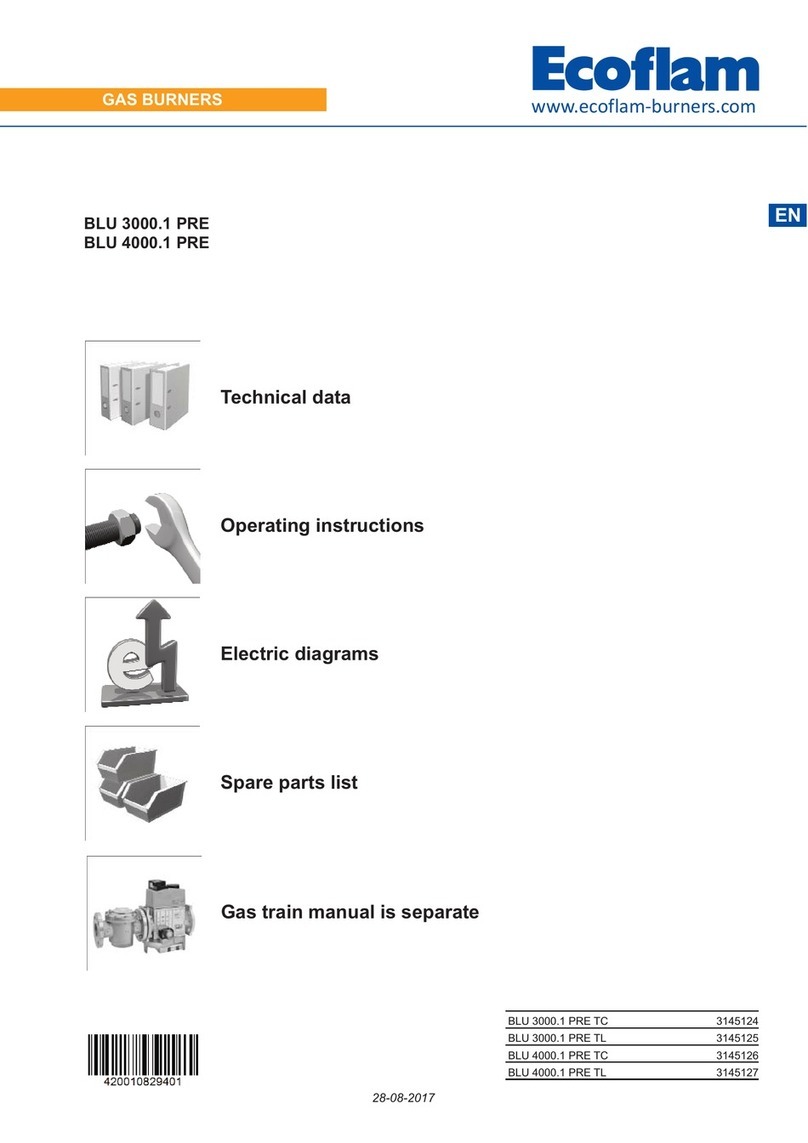
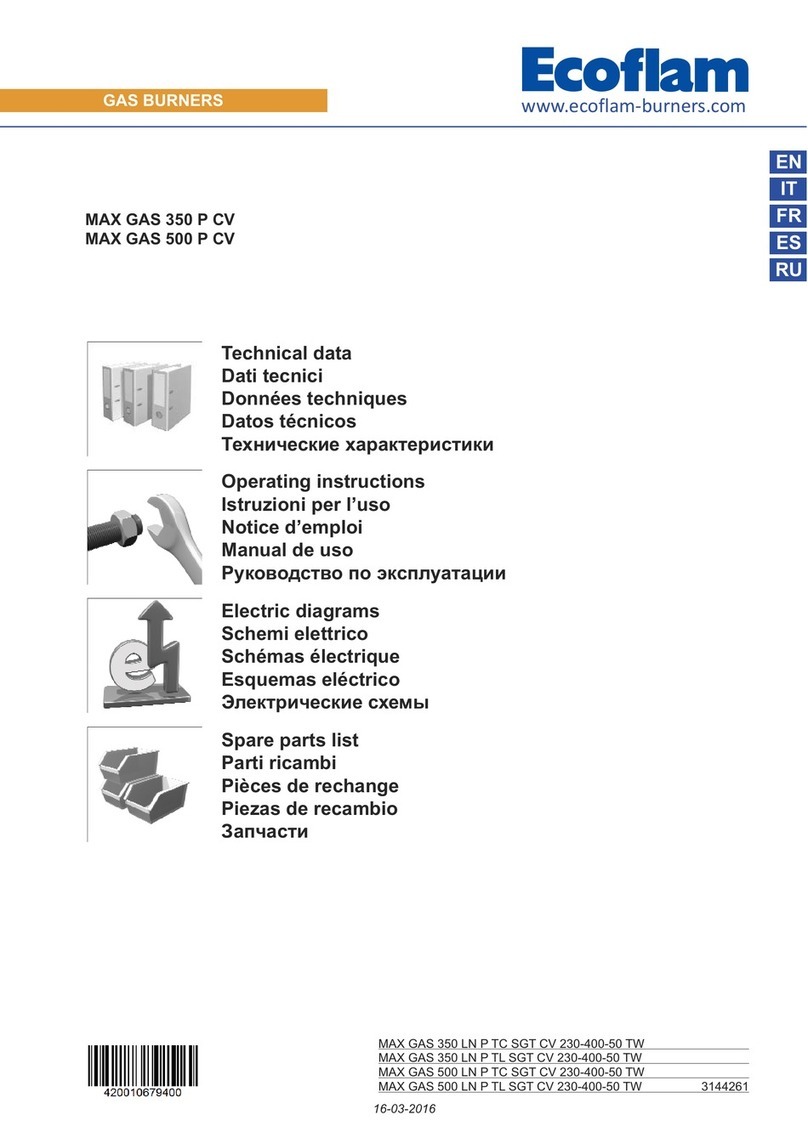
GAS/LIGHT OIL BURNERS
EN
Technical data
Operating instructions
Electric diagrams
Spare parts list
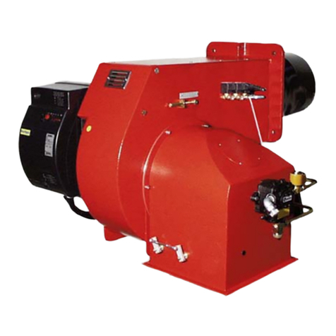
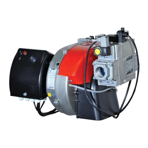
MULTICALOR 300.1 PR
MULTICALOR 400.1 PR
Gas train manual is
separate
www.ecoflamburners.com
MULTICALOR 300.1 PR TC SGT 230-400-50 3142642
MULTICALOR 300.1 PR TL SGT 230-400-50 3142643
MULTICALOR 300.1 PR TL LPG 3147139
MULTICALOR 400.1 PR TC SGT 230-400-50 3142644
MULTICALOR 400.1 PR TL SGT 230-400-50 3142645
MULTICALOR 300.1 PR TC SGT 230-400-50 NS 3143765
MULTICALOR 300.1 PR TL SGT 230-400-50 NS 3143766
MULTICALOR 400.1 PR TC SGT 230-400-50 NS 3143767
MULTICALOR 400.1 PR TL SGT 230-400-50 NS 3143768
11-05-2021
INDEX
MULTICALOR 300.1
MULTICALOR 400.1
0 1000 2000 3000 4000 6000 kW5000
420010461601
EN
www.ecoflam-burners.com
2
General warnings 3
Conformity declaration 4
Burner designation - Modular delivery system 5
Burner description 6
Electrical control panel 6
Gas train - Kit - Accessories: assembly to the burner 7
Technical data 8
Gas category by country 8
Working diagrams 9
Test boiler - Flame dimension 9
Overall dimensions 10
Oil operating mode - General safety functions 11
Gas operating mode - General safety functions 12
Installation 13
Fitting the burner to the boiler 13
Oil connection 14
Feeding and suction line for light oil 15
Gas line 16
Pilot gas train, kit and accessories connection - Head loss diagram 17
Gas pressure loss diagrams 18
Electrical connections 20
Start-up: checking procedure 21
Exhaust gas test 22
Start-up oil side 23
Fuel selection - Start-up 23
Adjusting the max air flow rate 23
Firing head setting 23
Adjusting the max oil flow rate 24
Servomotor SQM50 - Air damper motor pre-setting 24
Adjusting the pump pressure 24
Adjusting the intermediate burner capacity 25
Servomotor SQM50 - Oil side final setting 25
Start-up gas side 26
Fuel selection - Start-up 26
Adjusting the max air flow rate 26
Firing head setting 26
Servomotor SQM50 - Air damper motor pre-setting 26
Adjusting the intermediate burner capacity 27
Pressure switch adjustment 27
Servomotor SQM50 - Gas side final setting 27
Maintenance program 28
Troubleshooting instructions 30
Operating troubles 31
Appendix 32
Control box - Damper actuators 32
Fluidics nozzle chart 34
Bergonzo nozzle tables 37
Pump and pressure regulators 39
Electrical diagrams 40
Spare parts list 42
420010461601
EN
www.ecoflam-burners.com 3
GENERAL WARNINGS
BURNER SELECTION: Type of
operation and configuration must
be done by professional personnel
in order to grant correct working of
the burner. Installation, start-up and
maintenance must be carried out by
authorised specialists and all applicable
guidelines and regulations (including local
safety regulations and codes of practise)
must be observed.
Important notes
Ecoflam burners have been designed and
built in compliance with all current
regulations and directives.
All burners comply to the safety
and energy saving operation
regulations within the standard
of their respective performance
range.
The burner must not operate out-
side the working range.
The quality is guaranteed by a quality and
management system certified in
accordance with ISO 9001:2008.
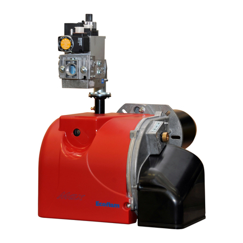
MULTICALOR burners are designed for
the low-pollutant combustion of natural gas
or LPG with kit and light oil.
The burners comply with
standard EN676. Assembly and
commissioning must be carried
out only by authorised
specialists and all applicable
guidelines and directives must
be observed.
Burner description
MULTICALOR PR burners are progressive
mechanical fully automatic monoblock
devices. Burner head is designed to get
the lowest emissions in terms of NOx and
unburnt particles in order to maximize the
heat generator efficiency. Emissions can
be different respect to the ones recorded in
the lab because they depends a lot on the
generator on which the burner is fit.
The installer must comply with compulsory
rules. Avoid for instance dangerous
atmosphere or not ventilated rooms.
Packaging and handling
Move the burner still in its packaging using
a trolley or forklift, taking care not to drop it
and elevating it no more than 20cm from
ground level. After having removed the
packaging, check that the contents are in
good condition and correspond with what
was ordered. If in doubt, contact the
manufacturer.
The burner must be installed by a
qualified individual.
If the weight and dimensions do not allow
for manual lifting, ask another operator for
help or use a forklift, harness the burner
using belts if no eyebolts are available.
Use the accessories provided
(flange, gasket, pins and nuts) to
install the burner onto the boiler,
taking care not to damage the
isolating gasket.
We can accept no warranty liability
whatsoever for loss, damage or injury
caused by any of the following:
- Inappropriate use.
- Incorrect assembly or repair by the
customer or any third party, including the
fitting of non-original parts.
- non authorised modifications made on
the burner.
Provision of the system and the
operating instructions
The firing system manufacturer must
supply the operator of the system with
operating and maintenance instructions on
or before final delivery. These instructions
should be displayed in a prominent
location at the point of installation of the
heat generator, and should include the
address and telephone number of the
nearest customer service centre.
Notes for the operator
The system should be inspected by a
specialist at least once a year. It is
advisable to take out a maintenance
contract to guarantee regular servicing.
WARNING
DANGER
WARNING
WARNING
WARNING
Gas lines
When installing the gas lines and gas train,
the general EN676 directives and
guidelines must be observed.
Additional accessories and kits shall be
installed by the installer in accordance to
the local safety regulations and codes of
practise.
Installation location
The burner must not be operated in rooms
containing aggressive vapours (e.g. spray,
perchloroethylene, hydrocarbon
tetrachloride, solvent, etc.) or tending to
heavy dust formation or high air humidity.
Adequate ventilation must be provided at
the place of installation of the furnace
system to ensure a reliable supply with
combustion air.
General regulations applying to the
gas connection
• The gas train must only be connected to
the gas mains by a recognised
specialist.
• The cross-section of the gas line should
be of a size designed to guarantee that
the gas flow pressure does not drop
below the specified level.
• A manual shut-off valve (not supplied)
must be fitted upstream of the gas train.
Ø r
Installing the gas train
The gas train is supplied
separately, for fitting refer to the
instructions in the gas train
manual.
WARNING
4 www.ecoflam-burners.com
EN
420010461601
CONFORMITY DECLARATION
5
www.ecoflam-burners.com
EN
420010461601
BURNER DESIGNATION
MODULAR DELIVERY SYSTEM
Dual fuel burners
All dual fuel burners are delivered in separate set/box, i.e. burner body including
combustion head and separate gas train with separate additional kit and accessories
that shall complete the gas train or the burner according to the applicable standard.
Kit and accessories are delivered separately.
Gas train - GTCP - KITS - Accessories
All gas and dual fuel burners gas trains are delivered separately in different models and
configuration.
Export configuration gas train completion are available but it is mandatory for the local
installer in this case to comply to the local safety regulations.
For burners over 1700 kW gas train connection pipe must be ordered.
Kits and accessories are managed and delivered separately.
Component type
BBCH Burner Body with Combustion Head (without gas train)
GTCP Gas Train Connection pipe
GT Gas Train (delivered separately)
MULTICALOR 300.1 PR TC SGT 230-400-50
MULTICALOR Dual fuel (Gas / Light oil)
RANGE NAME BY FUEL TYPE
MULTICALOR 300.1 300 kg/h - 3000 kW
MODEL SIZE (Gas: kW; Oil: kg/h)
-Standard Class 2 - GAS EN676 (<120 mg/kWh)
-Standard Class 1 - OIL EN267 (<250 mg/kWh)
EMISSIONS
PR 2 stages progressive mechanical gas / oil
MD 2 stages modulating mechanical with PID
E2 stages modulating electronic
OPERATION TYPE
230-400V/50Hz 230-400 Volt, 50 Hz
ELECTRICAL POWER SUPPLY
TC Short head
TL Long head
HEAD TYPE
Natural gas
LPG Liquid gas
BIOGAS Biogas
FUEL
SGT Separate gas train
EQUIPMENT
6 www.ecoflam-burners.com
EN
420010461601
BURNER DESCRIPTION
GTCP
Control panel
20
23
24
19
LEGEND
1. Housing
2. Electrical control panel
3. Blower motor
4. Pump and pump motor
6. Blast tube
8. Burner fixing flange
9. Air flap regulation
11. Silencer
12. Lifting eyebolts
13. Mechanical cam gas
14. Mechanical cam oil
15. Servomotor for gas and air
16. Gas train
17. Pilot gas train
18. Oil pressure regulator
19. Gas filter
20. Ball valve
21. Oil coil
23. Antivibration coupling
24. Tightness control
GTCP. Gas train connection pipe
16
1
6
8
12
1
9
11
3
20
19
4
18
15
17
14
13
2
A - reset key
B - operating lamps (orange=light-oil; green= gas)
C - selector:
OUT = loking of devoices foroperating at intermediate outputs
UP= operation at max. output
LOW = operation at min. output
AUTO = automatic operation
D - ON/OFF switch
E - selector:
0 = STOP
1= light-oil operation
2= automatic operation
3= gas operation
F - termal lock-out lamp
G - modulating unit RWF 50 (optional)
E
A
C
D
SAL
SA s.r
HLBT
HLoil
HLgas
SAMA
R
V
R
0=STOP
1=UP
2=LOW
3=AUTO
0 1
RWF 40
0: OFF
1: ON
SAgG
G
B
F
2=AUTO
3=GAS
1=OIL
0=STOP
21
7
www.ecoflam-burners.com
EN
420010461601
M
Air
Gas
313
160
170
144
142
141
120
150
314
349
151
155
100
143
Tobe supplied by the installer
107
143
Antivibration
coupling
144 Gas governor
150 Batterflyvalve
151 Gas train Siemens VGD....
155 Pilot gas train
160 Kit tightness control (optional)
170 Kit tightness control for pilot gas valve (optional)
313 Min.gas pressure switch
314 Max.gas pressure switch (optional)
349 Air/gas damper motor
BURNER DESCRIPTION
Gas train - Kit - Accessories: assembly to the burner
MATCHING GAS TRAIN WITH DIAGRAM OF PRESSURE DROPS
ARE IN THE DEDICATED SECTION OF THIS MANUAL
VGD 20.503 Rp 2” / VGD 40.065 - 40.080 - 40.100 - 40.125 1. Main gas pipe
2. Ball valve ACS
3. Antivibration coupling ACS
5. Min gas pressure switch
EXPORT
GAS TRAIN
EN676
6. Safety gas valve + 10. Actuator
7. Working gas valve + 11. Actuator
8. Gas leakage control KITTC *
9. Gas filter ACS
KIT - MAX Gas pressure switch KITPRES
ACS - Gas train connection pipe GTCP **
!GTCP-...* WARNING: in order to fit the gas train, the corresponding connection pipe must be ordered (GTCP size and fitting depend on the
burner and the gas train selected).
!WARNING: EN676 compulsory kit and accessories in order to comply to the safety regulations. Additional accessories and kits
shall be installed by the installer in accordance to the local safety regulations and codes of practise.
HOW TO INSTALL THE GAS TRAIN INTO THE BURNER AND CALCULATE THE OVERALL DIMENSIONS:
refer to the dimension page and the gas train manual for all detailed information
Gas governor / Filter
FGDR - FILTER
Compulsory EN676
Tightness control
KITTC- Model
Compulsory > 1200 kW
Max Pressure switch
KITPRES50
KITPRES150
Other accessories
Ecoflam gas trains are delivered separately for all gas and dual fuel burners and are available in different configurations:
Double gas valves with actuators and regulator VGD Siemens and min pressure switch + ACS gas filter
12 3 911810
5
67
Modulation Kit
KITMD-RWF50
Probe-...
8 www.ecoflam-burners.com
EN
420010461601
TECHNICAL DATA
GAS CATEGORY BY COUNTRY
MODEL MULTICALOR 300.1 MULTICALOR 400.1
Thermal power max.
kW 3.000 3.900
kcal/h 2.580.000 3.354.000
kg/h 253 330
Thermal power min.
kW 630 875
kcal/h 541.800 752.500
kg/h 53 74
Operation mode Type Progressive mechanical oil / gas - Modulating with PID
Regulation ratio nominal Type 1÷4 GAS - 1÷3 OIL
Fuel Type
G20 (L.C.V. 8.570 kcal/Nm3), G25 (L.C.V. 7.370 kcal/Nm3)
G31 (L.C.V. 22.260 kcal/Nm3), G30 (L.C.V. 29.320 kcal/Nm3)
Light oil (L.C.V. 10.200 kcal/kg max visc. 1,5°E at 20°C)
Emission class std Standard Class 2 GAS EN676 (<120 mg/kWh) -
Standard Class 1 OIL EN267 (<250 mg/kWh)
Control unit Type LFL / LGK
Gas train GT VGD separate gas train + Filter + KIT Tightness control + Other KIT/ACS
Gas connection GTCP Gas connection range RP 50 to DN 100 depending on the gas train selected
NATURAL GAS pressure mbar 22÷500 30÷500
LPG pressure mbar 45÷500 70÷500
Air regulation Type Air flap Air flap
Air flap control with servomotor Model SQM50
Air pressure switch mbar 1…10 mbar
Flame monitoring Type UV cell QRA
Ignitier Model BRAHMA
Motor kW 5,5 7,5
Rpm N° 2.800 2.800
Voltage V/Hz 230/400 V - 50 Hz
Total power consumption operation W8.250 9.500
Weight body BBCH Kg
Electrical panel protection level IP IP55 IP55
Sound pressure level
without silencer dB(A)
Lab
tests
87,3 88,3
Sound pressure level
with silencer 81,8 83
Ambient temperature storage Min/Max -20°…+70° C
Ambient temperature use -10°…+60° C
Oil pump Model TA3 TA3
Oil pump motor kW 0,74 kW 0,74 kW
Nozzles Type according to the output requested
Gas category Country
II2R3R BE CH CZ DE DK ES FI FR GB GR HU IE IT LU NL PT SE EE LT LV NO PL SK SI -
II2H3B/P AT - - - - - - - - - - - - - - - - - - - - - - - -
I3R CY MT - - - - - - - - - - - - - - - - - - - - - - -
9
www.ecoflam-burners.com
EN
420010461601
0
5
1
0
1
5
2
0
2
5
0 1000 2000 3000 4000 5000
0 1000 2000 3000 4000
0 100 200 300 400
kW
mbar
kg/h
kcal/h*1000
MULTICALOR 300.1
MULTICALOR 400.1
WORKING DIAGRAMS
TEST BOILER - FLAME DIMENSIONS
The burner/boiler matching does not pose
any problems if the boiler is CE type-
approved.
If the burner must be combined with a
boiler that has not been CE type-approved
and/or its combustion chamber dimensions
are clearly smaller than those indicated in
diagram, consult the manufacturer.
The firing rates were set in relation to
special test boilers, according to EN676 -
EN267 regulations.
The sizes are indicative and dipend on
the configuration, to the combustion
chamber pressure and to the draught.
The values have been taken out from
tests executed with flame tubes.
The dimensions of the flame are made
in test boiler in laboratory without
resistence therefore exists max and
min lenght that take into account the
difference in lenght that comes from the
boiler backpressure.
Example:
Burner thermal output = 8000 kW;
L flame (m) = 5 m (medium value)
D flame (m) = 1 m (medium value)
WARNING: Some flame modifications
can be done in our FLEXSHOP in the
factory in order to shape the flame and
adapt it to some special boiler
or application.
L (m)
2000 3000 4000 5000 6000 7000 8000 9000 10000
4
5
1000
2000 3000
1000
6
11000
0
2
3
7
8
12000 kW
13000
9
10
11
Nm3/h
100 200 300 400 500
kcal/h
x 1000
4000 5000 6000 7000 8000 9000 10000 11000 12000 13000 14000 15000
14000 15000 16000 17000
Ø (m)
2000 3000 4000 5000 6000 7000 8000 9000 10000
0,6
0,8
1000
2000 3000
1000
1
11000
0
0,2
0,4
1,2
1,4
12000 kW
13000
1,6
1,8
2
kcal/h
x 1000
4000 5000 6000 7000 8000 9000 10000 11000 12000 13000 14000 15000
14000 15000 16000 17000
FLAME LENGHTGAS BURNERS
FLAME DIAMETER GAS BURNERS
600 700 800 900 1000 1100 1200 1300 1400 1500 1600 1700
Nm3/h
100 200 300 400 500 600 700 800 900 1000 1100 1200 1300 1400 1500 1600 1700
Working diagrams
The working diagram shows
burner output as a function of
combustion chamber pressure.
It corresponds to the maximum
values specified by EN 676
measured at the test fire tube.
Boiler efficiency should be
taken into consideration when
selecting the burner.
Calculation of
burner output
QF= Burner output (kW)
QN= Rated boiler output(kW)
η = Boiler efficiency (%)
QF= QNx 100
η
10 www.ecoflam-burners.com
EN
420010461601
I
M
L
ED - D1
F
C
B
A
G
N
O
SUNTEC
SUNTECSUNTEC
1
0
2
3
I
O
1
0
2
H1
OVERALL DIMENSIONS
HOW TO INSTALL THE GAS TRAIN
INTO THE BURNER AND CALCULATE
THE OVERALL DIMENSIONS:
refer to the dimension page and the gas train
manual for all detailed information.
Fixing hole dimensions
are “I” and “L” as per
dimension table.
Boiler hole shall be done
according to the blast
tube dimension “F” plus
15-25 mm in order to be
able to extract it during
maintenance.
Burner-boiler mounting flange
Packaging (only burner)
WARNING: Please follow the suggested dimension for the hole on
the boiler flange in order to fit the burner. Make sure that between
the boiler and the blast tube proper insulation is fitted.
Models X Y Z kg
MULTICALOR 300.1 1750 2380 1460
MULTICALOR 400.1 1750 2380 1460
Dimensions (mm)
D = Short head
D1= Long head
X
Y
Z
Models A B C D D1 E F G H1 I L M N O
MULTICALOR 300.1 1230 610 620 330 530 900 290 471 746 315 315 M16 195 250
MULTICALOR 400.1 1230 610 620 345 545 900 320 471 746 315 315 M16 195 250
365
365
315
315
Burner gas flange
Model ø A1 B1
MULTICALOR 300.1 145 4 x M16
MULTICALOR 400.1 145 4 x M16
A1
B1