Ecolab Aquanomic User manual


Page 2
Materials Ordered Separately for Installation
MATERIALS ORDERED SEPARATELY .................................................................................................................................................... 3
1.0 SYSTEM INTRODUCTION...................................................................................................................................................3
1.1 PREFACE ................................................................................................................................................................................. 3
1.2 SYSTEM FEATURES .................................................................................................................................................................... 4
1.3 PRINCIPLE OF OPERATION........................................................................................................................................................... 5
1.3.1. Condor Controller................................................................................................................................................. 6
1.3.2. Machine Signal Interface Module (MSI) .............................................................................................................. 6
1.3.3. Formula Select Module (FS) ................................................................................................................................. 6
1.3.4. I/O Circuit Board .................................................................................................................................................. 6
1.3.5 Pump Cabinet....................................................................................................................................................... 7
2.0
REQUIREMENTS/SPECIFICATIONS
...................................................................................................................................8
2.1
U
TILITY
R
EQUIREMENTS
................................................................................................................................................... 8
2.1.1. Electrical Supply Requirements............................................................................................................................ 8
2.1.2. Water Supply Requirements ................................................................................................................................ 8
2.2
P
UMP
C
ABINET
S
PECIFICATIONS
......................................................................................................................................... 9
2.3
C
ONDOR
C
ONTROLLER
.................................................................................................................................................... 10
2.4
M
ACHINE
S
IGNAL
I
NTERFACE
M
ODULE
(MSI)
................................................................................................................... 11
2.5
F
ORMULA
S
ELECT
M
ODULE
(FS)
...................................................................................................................................... 11
3.0
SYSTEM INSTALLATION
..............................................................................................................................................12
3.1
P
REPLANNING
...................................................................................................................................................................... 12
3.2
M
ATERIALS
O
RDERED
S
EPARATELY
........................................................................................................................................... 12
3.3
H
ANGING THE EQUIPMENT
...................................................................................................................................................... 13
3.3.1. Pump Cabinet Installation.................................................................................................................................. 13
3.3.2. Condor Controller Installation............................................................................................................................ 14
3.3.3. Formula Select (FS) Installation ......................................................................................................................... 15
3.3.4. Machine Signal Interface (MSI) Installation....................................................................................................... 15
3.4 INSTALLATION WIRING .............................................................................................................................................
16
3.4.1. Pump Cabinet Wiring......................................................................................................................................... 16
3.4.2. RS-485 Communication Cables .......................................................................................................................... 16
3.4.3. I/O (Input/Output) Board Cable (inside Pump Cabinet) ..................................................................................... 17
3.4.4. Condor Controller Cable..................................................................................................................................... 17
3.4.5. Formula Select (FS) Cable and Address Setup .................................................................................................... 18
3.4.6. Machine Signal Interface (MSI) Cable and Address Setup ................................................................................. 18
3.4.7. Washer Supply Signal Wiring (MSI Module) ...................................................................................................... 18
3.4.8. Chart Stop (Machine Hold) Wiring (MSI Module) .............................................................................................. 20
3.4.9. MicroMode Signal Wiring (MSI Module) ........................................................................................................... 20
3.5
I
NSTALLATION
P
LUMBING
(
PUMP CABINET
)
................................................................................................................................. 21
3.5.1. Product Injection –Tube Installation ................................................................................................................. 21
3.5.2. Overflow Connection ......................................................................................................................................... 21
3.5.3. Hot Water Supply Connection............................................................................................................................ 22
3.6
O
PTIONAL
4
TH
S
OLID
P
RODUCT MODULE
.................................................................................................................................... 23
3.6.1. Introduction ....................................................................................................................................................... 23
3.6.2. Requirements/Specifications ............................................................................................................................. 23
3.6.3. Installation Procedure........................................................................................................................................ 24
3.7
O
PTIONAL
B
LEACH
P
RODUCT
H
OUSING
..................................................................................................................................... 26
3.7.1. Introduction ....................................................................................................................................................... 26
3.7.2. Installation......................................................................................................................................................... 26
3.8
O
PTIONAL
4
TH
LIQUID
PRODUCT
PUMPS
.............................................................................................................................. 28
3.8.1. Installation......................................................................................................................................................... 28

Page 3
Materials Ordered Separately for Installation
•10mm O.D. flexible copper tubing or G3/8 stainless steel braided hoses.
•1/2-inch O.D., 3/8-inch I.D., Polyflo (PolyEthylene, PE) tubing used for product delivery from the
Pump Cabinet to the laundry machine(s). This rigid tubing withstands higher temperatures than soft
EVA.
•The 5/8-inch I.D. Mayon tubing used for the overflow is not included in the installation kit.
•1/2-inch conduit or Seal-Tite with connectors and fittings (hardwired power source and supply
signals).
•Electrical plug for power cord must be sourced and installed separately.
•A main switch (EBS Nr. 10010678) or non symmetric plug is mandatory.
•Proper wall anchors or toggle bolts should be used on sheetrock walls.
•Water Tempering Valve Kit if the account hot water temperature is greater than 60°C.
•Optional 15m (50-feet) RS-485 communication cable are available.
•Optional L-brackets for mounting Condor Controller or FS modules.
1.0 System Introduction
1.1 Preface
This manual has been written and illustrated to present the basic installation and servicing instructions of the
Aquanomic EU solids dispenser. This manual applies to current units. Future versions may have additional
features; check unit packing for the latest revision.
Guidelines will be suggested in reference to the preferred method of installation. However, the variety of
equipment and the surrounding environment will dictate the actual installation of the Aquanomic EU unit.
These installation, operation and servicing instructions are for use by qualified personnel only. The Aquanomic EU system is intended to be
installed by an experienced, qualified technician. The installation must be made in accordance with all applicable and local plumbing and
electrical codes. The dispenser must be properly plumbed to a laundry washer / extractor. The washer extractor must have a properly
installed drain system or overflow protection system.
The remarks WARNING, CAUTION and NOTICE have the following meanings in this manual.
This heading refers to a hazard or unsafe practice which can result in severe personal injury or death.
This heading refers to a hazard or unsafe practice which can result in personal injury or product or property damage.
This heading is used when a particular piece of information needs to be highlighted.

Page 4
1.2 System Features
The Aquanomic system is a solid laundry chemical dispensing system with capability to add liquid
pumps. The system provides for flexible installation to service up to (3) laundry washing machines.
•Service up to (3) washing machines
-22 –135 lbs. or 10 –61 kg (dry linen weight)
-Total system capacity = 270 lbs. (122 kg)
•Capable of programming/selecting up to 15 different wash formulae per washer
-Each formula may be programmed with up to 6 washer signals / steps
-Each step can be programmed for up 3 solids (4th Solid or 1 liquid is optional)
-Enter the desired solid product amounts directly in grams
-Enter the desired liquid product amounts directly in ounces (or milliliters)
-Automatic Product Dose Scaling for washer size
•Machine Signal Interface (MSI) automatically adjusts for 24 –240VAC and 22 –24VDC signals.
•Integrated Chart Stop with programmable delay start and stop length –No add-on equipment
required.
•Chart Stop timers and delays may be programmed for any formula.
•MicroMode feature provides automatic formula control from the washer.
•Automatic recording –the number of times each formula has been used (load counter).
•Queue Tracking.
•Selectable operating logic allows the unit to be used with all washer styles.
•Multiple user language options with region-specific weights and units of measures.
•Icon-based display for ease of training and use.
•Visual & audible system alarms.
•Backlit display on Formula Select (FS) module for ease of program selection.
•Dispenses (3) solid laundry products from their respective capsules (Detergent, Bleach, and
Sour/Softener).
•Each product is electronically measured while dispensing into the laundry machine for accuracy.
•Additional 4th Product Solid dispenser is available.
•Optional 4th Liquid System utilizes safe, accurate diaphragm pump technology for low maintenance
operation and long life.

Page 5
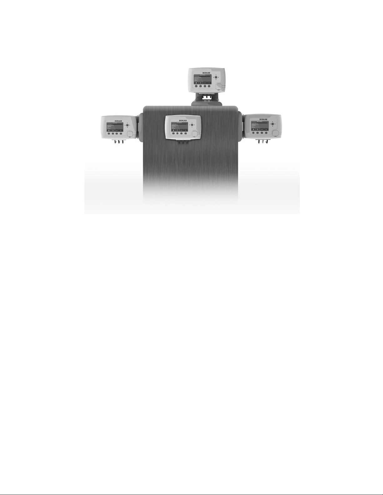
1.3 Principle of Operation
The Aquanomic system works by communicating between 4 main modules: Condor Controller, Pump
Cabinet (with I/O board), Machine Signal Interface (MSI), and Formula Select (FS). There is always 1
Condor Controller (the brains of the system) and 1 Pump Cabinet (where products are dispensed). There
can be up to 3 MSI and up to 3 FS (depends on the number of laundry machines being serviced). All of
these modules communicate using the RS-485 cables running between them in series or “Daisy Chain.”
Therefore, each module has 2 RS-485 cable ports, both need to be used for cables or with an end plug.
The Pump Cabinet dispenses 3 solid products, but you can add a 4th solid product or a liquid product using
optional equipment.
Do not plug or unplug RS-485 cables when power is applied to the system. Do not apply power to the system until all modules are
properly addressed and all RS-485 cables and plugs (dongles) are properly connected to the modules.
IO BOARD
CONNECTIO
NS
FORMU
LA
SELECT
(FS)
MACHINE
SIGNAL
INTERFACE (MSI)
RS-485
PLUG
(DONGLE)
CONDOR
CONTROLLE
R
RS-485
CABLES
RS-485
PLUG
(DONGLE)
OR CABLE
TO
WASHER
#3
DISPENSE
R
WASHER
#1
WASHER
#2
COMMUNICATION CABLE EXAMPLE (2-WASHER)

Page 6
1.3.1 Condor Controller
The Condor Controller is the main controller for the system. This module is the interface between the user
and the system. All of the programming features, report data, and diagnostic tools are available here. The
Condor Controller can also be used to select wash formulae. A wash formula selection made on the
Controller will be shown on the corresponding Formula Select module. If the Formula Select modules are
not installed on the laundry washer, the formula selections must be made using the Condor Controller when
MicroMode is not in use. The Condor Controller should be mounted in a location that is accessible to the
customer and service technician. The communication connection for a tablet or other mobile device is
located on the front of the Condor Controller. Audible and visual alarms come from this module.
1.3.2 Machine Signal Interface Module (MSI)
The MSI module is installed at the laundry machine control wiring area, typically on the back of the washing
machine. It receives the laundry machine supply signals and automatically converts them from machine
voltages (24 - 240VAC or 22 - 24VDC) to dispenser signal voltages (24VDC). Once a signal is received and
validated, the system will dispense products based on the selected formula. Chart Stop output wiring
connections are available at the MSI.
1.3.3 Formula Select Module (FS)
The FS module is typically mounted on the front of the laundry machine. It is used to select the wash
formula on the dispenser when a new cycle is started. The selected formula is displayed on the screen. Any
active alarms will be displayed on the screen of each FS as well as the Condor Controller.
If MicroMode is in use, the wash formula does not need to be manually selected on the Formula Select
module. The formula will be automatically communicated from the washer to the dispenser via the washer
MicroMode signal. In this mode, the FS is optional, but can still be used to convey system’s information to
the user.
This module is optional for accounts where MicroMode is in use or if wash formula selection will only be
made using the Condor Controller.
1.3.4 I/O (Input/Output) Circuit Board
The I/O circuit board is found inside the plastic enclosure, inside the Pump Cabinet. The board INPUTS
signals from the Condor Controller to turn on valves and pumps then OUTPUTS information as to amount of
product dispensed (using conductivity probes) and temperatures (thermistor). The Pump Cabinet dispenses
products when the I/O board receives a request from the Condor Controller after the MSI receives a signal
from the machine. The I/O board within the pump cabinet processes the request based on the product
requested, gram amount, delay time, and chart stop time.

Page 7
1.3.5. Pump Cabinet
The Pump Cabinet is the product dispenser that sprays hot water into 3 solid product capsules. The product
solution gravity drains into the pump, then the pump pushes the solution through a washer selection
manifold and 1 of 3 valves will open to determine which washer the product goes to. The system delivers
product(s) to the correct washer based on the programmed values. The system continuously measures the
product and will notify the operator when the capsule is empty. The empty alarm consists of an audible
alarm and icon on both the Condor Controller and the Formula Select. Before each product spraying, there
is a pre-flush and post-flush of water only- to clear out the sump and pump’s tubing to prevent products from
mixing.
Hydraulic Diagram inside Pump Cabinet
Hot Water
Back flow prevention RPZ / BA
Main Water
Solenoid Valve
Pressure
Gauge
Detergent
Solenoid
Valve
Pressure
Regulator
Water
Strainer
Detergent
Nozzle
Bleach
Solenoid
Valve
Softener
Control
Valve
Pump Inlet
Hose
Pump
Discharge
Manifold
Thermistor
Washer
Machine #1
Solenoid
Conductivity
Cell Electrodes
#1 #2 #3
Check Valves
Pre & Post
Flush Nozzle
Bleach
Nozzle
Sour /
Softener
Nozzle
Washer
Machine #3
Solenoid
Sump
N.O.
N.C.
For back flow
prevetion , See
RPZ Installation
guide.

Page 8
2.0REQUIREMENTS/SPECIFICATIONS
2.1. Utility Requirements
2.1.1 Electrical Supply Requirements
•
A constant 230 VAC /50 -60 Hz. power source is required.
•
The Pump Cabinet is shipped with a 2.7m (9-foot) power cord.
•
A main switch (EBS Nr. 10010678) or non symmetric plug is mandatory.
•
The ON /OFF circuit breaker switch is rated at 3.0 amps.
•
Total amperage draw during normal operation is less than 1.8 amps.
2.1.2.Water Supply Requirements
•Watertemperatureshouldbe between 49°C –60°C (120°F –140°F).
•
Water supply pressure: 1.5 –1.8 bar (22 - 26 psi) (during dispense mode).
•
Water flow rate is 3.0 –4.5 liters/min (0.8 - 1.2 GPM).
Risk of Injury
- Contact with contents can cause skin burns and serious eye injury.
- Wear eye and skin protective equipment.
Refer to Product Safety Data Sheets for further information.
Complex Requests from different washers will be dosed in a FIFO (First In, First Out) basis and do not have the ability to be split up (unlike the
case of one complex request with multiple simple requests) so use caution when setting up Product Delays to prevent the system from
sitting idle waiting for different Product Delays to expire.
To avoid operator exposure to chemical products, the queue system will automatically cancel the final step of a wash formula if it is in queue
(waiting) for longer than 3 minutes. If the final washer step includes a chemical dose, it is important that the washer step programmed length
is greater than 3 minutes.

Page 9
2.2. Pump Cabinet Specifications
Dimensions
The dimensions of the Pump Cabinet are shown below:
•Height (H1): 56 cm
•Height (H2): 20 cm
•Width (W): 58 cm
•Depth (D): 25 cm
•Weight: 27 kg (35 kg with products)
Product Capsule
H
2
Clearance
H
1
D W
ServiceAccess
The removable, metal front cover is held in place by a key lock, located under cabinet, front and center.
Hold the front cover on the sides and lift up, then tilt bottom forward to disengage bottom groove.
A minimum clearance of 20 cm is required above the dispenser in order to facilitate changing capsules.
Turn off all power to the Pump Cabinet before servicing.

Page 10
2.3. Condor Controller
Dimensions
W
20 cm
H
14 cm
D
7 cm
Mounting Clearance
(bottom)
7 cm
Dimensions
W1
16 cm
W2
20 cm
H
20 cm
D
9 cm
Dimensions
W
24 cm
H
16 cm
D
9 cm
Mounting Clearance
(bottom)
7 cm
Condor Controller mounted directly to flat wall.
Condor Controller mounted to table surface, using optional L-bracket 9200-2132.
Condor Controller mounted to opposite wall surface, using optional L-bracket 9200-2132.
W
W1
W2
W
H
H
H
D
D
D

Page 11
2.4. Machine Signal Interface Module (MSI)
2.5. Formula Select Module (FS)
Dimensions
W
15 cm
H1
20 cm
H2
24 cm
D
6 cm
Weight
1.7 lbs
Mounting Clearance
(bottom)
7 cm
Dimensions
W
14 cm
H
14 cm
D
6 cm
Mounting Clearance
(bottom)
7 cm
The FS module can also use the optional L-bracket (9200-2132) for additional mounting configurations.

Page 12
3.0SYSTEM INSTALLATION
3.1
Preplanning
There is no substitute for planning the installation prior to beginning the work. Several minutes in planning
may save an hour or more during the installation. The following is a list of factors to consider before the
installation of the system begins.
Under normal installation procedure the Pump Cabinet MUST BE located within 50-feet (15 meters) of all 3
laundry machines. Outlet tubing should not exceed 50-feet in length under normal operation. This is
important to know when positioning the Pump Cabinet. A shorter distance is preferable to help reduce post-
flush times. Long dispense distances require extended flush times.
The dispenser system comes with (5) 4.2m (14-feet) long and (2) 7.6m (25-feet) long RS-485
communication cables. Optional 15m (50-feet) communication cables are available. This is important to
know when positioning the modules.
The Pump Cabinet MUST BE mounted at or below the operator’s eye-level. Ease of capsule replacement is
important.
Pump Cabinet’s wall mounting bracket MUST BE securely anchored to the wall. On sheetrocked walls, align
the center mounting hole to a wall stud or separately order toggle bolts (see below).
Allow sufficient space around the perimeter of the cabinet for capsule replacement and servicing. It is
recommended to allow 20 cm (8-inches) above Pump Cabinet.
3.2 Materials Ordered Separately
•Backflow Prevention Code 10004965 ; 10002009 and 10000440.
•1/2-inch O.D., 3/8-inch I.D., Polyflo (PolyEthylene, PE) tubing used for product delivery from the
Pump Cabinet to the laundry machine(s). This rigid tubing withstands higher temperatures than soft
EVA.
•The 5/8-inch I.D. Mayon tubing used for the overflow is not included in the installation kit.
•1/2-inch conduit or Seal-Tite with connectors and fittings (hardwired power source and supply
signals).
•Electrical plug for power cord must be sourced and installed separately.
•A main switch (EBS Nr. 10010678) or non symmetric plug is mandatory.
•Proper wall anchors or toggle bolts should be used on sheetrock walls.
•Water Tempering Valve Kit if the account hot water temperature is greater than 60°C.
•Optional 15m (50-feet) RS-485 communication cable are available.
•Optional L-brackets for mounting Condor Controller or FS modules.
Page 13
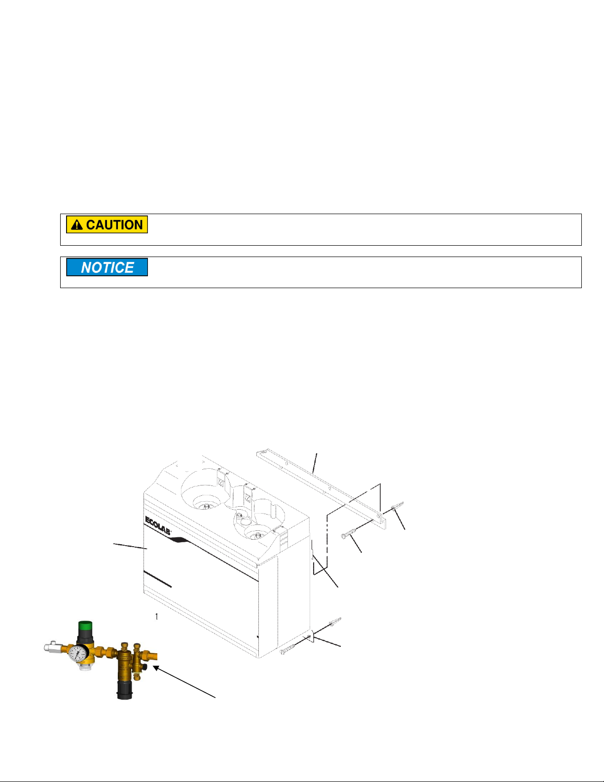
3.3 Hanging the Equipment
3.3.1. Pump Cabinet Installation
1. Positionthewall mountingbracket against the wall at eyelevel.
On sheetrock walls, align the center
mounting hole to a wall stud. WallMoun
ting bracket MUST BE securely anchored to the wall. Proper
wall anchors or toggle bolts should be used.
2. Usinga pencil,outlineeachoftheholesin theoffsetmountingwall bracket.
3. Drill theoutlined hole with a1/4-inch masonrybitand placea wall anchor (suppliedin theinstallation
kit)intoeach hole.
4. Securethe
wall bracket to the wall using
thesuppliedwallanchors.
Be careful when lifting the Pump Cabinet. It weighs 27 kg. If you must lift it by yourself, hold it close to your body.
On sheetrocked walls, align mounting holes with wall studs wherever possible.
5. Lift the Pump Cabinet up
and onto the mounting bracket, utilizing the mating bracket on the
back
of the
cabinet.
6.
With the Pump Cabinet on the wall, use a pencil to outline the center hole on the bottom flange.
7.
Remove the Pump Cabinet from the wall.
8. Drill theoutlined hole with a1/4-inch masonrybit andplacea wallanchor(suppliedin the installation
kit)intothehole.
9. Lift the Pump Cabinet back up and ontothemountingbracket.
10.
Secure the bottom flange of the Pump Cabinet to the wall using the wall anchor.
Backflow prevention to b e installed as close as possible to the Dispenser
Plastic Wall
Anchor
Mating Bracket on back of Pump Cabinet
Pump
Cabinet
Wall Mounting
Bracket
Center of Bottom Flange
Screw
Page 14
3.3.2. Condor Controller Installation
Select a location as close as possible to the Pump Cabinet but also access for programming. This will allow
for easier operation and maintenance. The visual and audible alarms comes from the Condor Controller.
1. Choose a location allowing visible display of the controller with the keypad accessible. Please avoid
locations where steam and splashing water occur.
2. To remove Condor Controller from mounting bracket, pull up on center tab and slide parts apart.
3. Using the wall mounting bracket as a template, mark 2 holes on the wall using a pencil.
4. Drill (2) holes using 1/4-inch drill bit and insert plastic wall anchors.
5. Using a screwdriver, mount bracket to wall.
6. Remove back cover to access RS-485 cable connections.
7. Tilt Condor Controller’s top forward and slowly guide Controller onto bracket.
For Dual Lock (Tape) Installation
1. Cut (4) 3-inch Dual Lock strips (provided in installation kit).
2. Squeeze (2) pieces of the Dual Lock strips together.
3. Apply the Dual Lock strips to back of Condor Controller bracket by removing the adhesive backing.
4. Remove the adhesive backing and stick unit to desired mounting location- on wall or machine.
For L-Bracket Installation - Optional
1. Mount L-bracket to top or side of washing machine. You may also use the Dual Lock tape.
2. Twist and lock Condor Controller’s bracket into the L- bracket.
3.3.3. Formula Select (FS) Installation
The FS is intended to be mounted to the front of the laundry washer as an operator accessible location using
the wall bracket or Dual Lock tape (provided in installation kit). The optional mounting L-bracket (ordered
separately) can also be used, similar to the Condor Controller Installation- see above.

Page 15
3.3.4. Machine Signal Interface (MSI) Installation
Disconnect electrical power supply to the washer, and follow lockout/tag-out procedures before installing or performing service on the
system. High voltage will be present.
Mount the Machine Signal Interface box to the laundry machine’s controller box using the Dual Lock tape
provided on the MSI module. Then run wires through conduit. The MSI module is installed typically on the
back of the machine. If receives the laundry machine supply signals (24 to 240 VAC or 22 to 24 VDC).
1. If no rear knock-out in machine controller box is present, drill a 7/8-inch hole in appropriate location on
chassis.
2. Remove Dual Lock adhesive backing on MSI module.
3. Route MSI washer signal wires and conduit elbow through 7/8-inch hole to the inside of the laundry
machine’s control box.
4. Apply pressure to MSI module to engage Dual Lock adhesive and secure conduit.

Page 16
3.4 Installation Wiring
3.4.1 Pump Cabinet Wiring
The dispenser requires constant 240 VAC to operate. The Pump Cabinet comes with a pre-installed 2.7
meter (9-foot) electrical cord. An appropriate electrical plug must be installed on the cord.
A main switch (EBS Nr. 10010657) or non symmetric plug is mandatory. This will avoid changing the
polarity, because some internal wiring is not subjected to 230 VAC, as it is for 110 VAC only.
Brown –line
Blue –neutral
Yellow/green –ground
Do NOT use power from a laundry machine to operate the dispenser.
This dispenser must remain powered constantly. Do not use outlets that may be shut off manually (GFI outlets are OK).
If the electrical cord can not be used, you must use a minimum cable wire of 14 gauge.
If a condition exists where the cord cannot be used (for example, distances greater than 2.7 meters) the
following procedure should be used.
1. Remove the existing BROWN and BLUE wires off of the terminal posts on the back of the ON/OFF circuit
breaker (BROWN is hot, BLUE is neutral).
2. Remove the GREEN wire with the YELLOW tracer from the ground lug (GREEN is ground).
3. Remove the 2.7 meter power cord from the Pump Cabinet.
4. Field wire a new HOT, NEUTRAL and GROUND WIRE within the Pump Cabinet.
5. Attach the HOT and NEUTRAL wires to the terminal posts on the back of the ON/OFF circuit breaker.
Use the same polarity as the cord installation. Brown is hot, blue is neutral.
6. Attach the GROUND wire to the grounding lug located on the front of the electrical box.
3.4.2. RS-485 Communication Cables
Each module has two communication ports (6-position white connectors). They are identical and completely
interchangeable. You may connect the communication cables to either port. When making the connection,
ensure the cable snap-locks (audible click) into the connector on the circuit board.
Do not plug or unplug RS-485 cables when power is applied to the system. Do not apply power to the system until all modules are
properly addressed and all RS-485 cables and plugs (dongles) are properly connected to the modules.

Page 17
The RS-485 cables are connected in a daisy-chain fashion. The first and last module in the sequence will have an open communication port.
A RS-485 plug or “dongle” must be plugged into the first and last open connector. There are (2) plugs in the install kit.
1. Mount all modules on the wall or machine.
2. Route cables from one module to the next module in a daisy chain sequence.
3. Now with all modules cabled together, go to the first and last module in the daisy chain sequence and
install a RS-485 plug or dongle in the (2) remaining ports. (The Condor may already have a dongle pre-
installed.)
4. Secure cables with zip ties for a clean installation.
All electrical connectors are keyed to fit one way only. Do not force the connections.
If you need to unplug a cable or plug- be careful. They have a locking mechanism tab that must be squeeze to release the tab. This squeeze
takes a lot of effect- for a very strong hold during normal operation.
Seven (7) RS-485 communication cables are included with the dispenser. All will be needed if the account has (3) laundry washers and all FS
modules are used. If longer or more cables are needed, they are ordered separately.
Do not secure or wrap the communication cables around, or near, any high voltage cables or components (48V or greater).
If communication is lost at any point in the sequence, all modules following this connection will also lose
communication. For example, if communication is lost or a communication cable is accidentally severed
(unplugged or cut) at Washer #1, communication will be lost to Washer #2 and Washer #3 and these
machines will not be serviced by the dispenser.
3.4.3. I/O (Input/Output) Board Cable (inside Pump Cabinet)
1. After Pump Cabinet is securely hanging on the wall, remove metal front cover, using keylock.
2. Remove plastic cover from plastic enclosure with (4) screws, the I/O board is inside.
3. Remove white plastic split strain reliefs in bottom of enclosure. The RS-485 cable will run through these.
4. Connect RS-485 cable to board and run cable over to closest module. Make sure to use the white
plastic split strain reliefs to capture cables.
5. Repeat step 4 or place Plug into port, if this module is the first or last in the chain of cables.
3.4.4. Condor Controller Cable
1. Remove Condor Controller from mounting bracket and remove back cover by loosening (2) retaining
screws.
2. Inside the Condor Controller only, you will find a termination plug already installed. If you wish this
module to be the first or last in the daisy chain, keep installed. Otherwise, remove the plug and place
into a different module that needs a terminating cable plug.
3. Connect either (1) or (2) communication cables of suitable length to make up the daisy chain of cables.
Replace back cover.
4. Attach Condor Controller back to mounting bracket.
Addresses must be consecutive. For example, if 3 washers are used, addresses must be set up as 1, 2, 3.

Page 18
3.4.5. Formula Select (FS) Cable and Address Setup
For cable wiring, see above the Condor Controller Cable and follow those directions.
1. Identify the washers and assign each of them an address (#1 - #3). The addresses must be unique and
cannot be duplicated, or a system communication error will occur.
2. Remove rear access cover on Formula Select module by first removing module from provided mounting
bracket and loosening the (2) back cover screws.
3. Locate the dial on the lower edge of the FS circuit board as shown below and set it to the appropriate
address of the assigned washer.
3.4.6 Machine Signal Interface (MSI) Cable and Address Setup
1. Remove front cover using (4) screws in the front cover.
2. Run RS-485 cables in and out of the enclosure using holes in bottom.
3. Identify the washers and assign each of them an address (#1 - #3). The addresses must be unique and
cannot be duplicated, or a system communication error will occur.
4. Locate the dial on the lower left corner of the MSI circuit board as shown below and set to the
appropriate address of the assigned washer.

Page 19
3.4.7 Washer Supply Signal Wiring (MSI module)
High voltage will be present.
Disconnect electrical power supply to the washer, and follow lockout/tag-out procedures before installing or performing service on the
system.
Electrical and grounding connections must comply with local electrical codes.
Individually wire-nut any unused wires. If the washer has a single common, wire-nut all of the commons together.
There are 8 Lights present on the MSI module, but only 6 will be used for products. The LEDs will illuminate when a valid signal is received at
the respective input.
There are 6 signal wires provided with the MSI Module assembly and their wiring colors are referred below:
Washer Signal # MSI Wire (Signal Hot) Signal Common (already shorted together)
#1 Black White
#2 Brown White
#3 Red White
#4 Orange White
#5 Yellow White
#6 Blue White
Washer 1, 2 or 3

Page 20
1. Once all MSI wiring from the conduit elbow is routed inside the laundry machine controller, locate the
washing machine supply signals inside the laundry machine.
2. Connect the green/yellow wire to the washer frame ground (earth ground).
It needs to be ensured, that the high-voltage AC signals from the machine dosing output board are of one
phase only.
The safety ground (green/yellow wire) on the MSI module must be properly connected to the machine safety
ground.
The MSI board automatically adjusts to accept 24-240 VAC (or 22-24 VDC) supply signals from the washing machine. For DC signals, Common
is the signal DC ground, positive DC voltages are connected to the hot signal wires.
All washer signals are converted to low voltage. A green LED will illuminate on the front of the MSI module when a signal is triggered from
the washer. A micro-processor circuit will send the validated signal(s) back to the Condor Controller via the communication cable
3. Identify and assign the washer supply signals. Check with technical service or with the washer
manufacturer if you are not sure of the connections.
4. Connect wiring from MSI module to washer supply signals.
5. Do NOT leave any exposed wires uncapped as they could cause an electrical short circuit inside the
washer controller box. Use electrical tape or wire nuts to cap off un-used wires.
The laundry machines are connected to ground via the power supply using the green/yellow wire.
If service is needed, sometimes the power connector is disconnected. In this case the machine loses safety
ground connection.
It is therefore mandatory to have a separate safety ground connection installed on the laundry machine
housing, which will be active at any time.
Proper grounding of the MSI and the washers will prevent high voltage on the machine signals.
3.4.8. Chart Stop (Machine Hold) Wiring (MSI module)
If needed for fixed timer washers, connect Chart Stop wires to the washer timer motor. Two gray wires are
pre-connected for Chart Stop connections. These wires provide a normally-closed dry contact that opens
when the controller calls for Chart Stop. This provides an interruption of the washer timer motor for the
programmed Chart Stop time.
1. Disconnect one wire from the machine timer motor and connect it to an open screw terminal in the
washer controller.
2. Add a supplemental wire (18 GA, 300V-rated insulation) from the timer motor, where the wire was
removed in step 1. Connect the other end of this supplemental wire to another open screw terminal.
3. Connect the two gray wires from the MSI to the new screw terminals in positions corresponding to the
motor timer wires.
4. Program the Controller for desired Chart Stop times for each product and formula.
3.4.9. MicroMode Signal Wiring (MSI module)
MicroMode allows formula selection to be performed automatically by the washer controller. The washer
controller must be microprocessor controlled and able to program supply trigger signal timed to the seconds.
1. Connect MicroMode signal from the washing machine to MSI Signal #1 (black wire).
2. Select MicroMode feature for each washer on the Condor Controller (3. System Menu> 1. Washer
Settings> 6. WE Signal Mode>MicroMode)
Other manuals for Aquanomic
1
Table of contents
Other Ecolab Dispenser manuals


Popular Dispenser manuals by other brands

Magnani
Magnani MI-HA-IHWD02-CB user manual

Fetco
Fetco D041 instructions

Adast Systems
Adast Systems AdBlue V-line 47 Series user manual

Nordson EFD
Nordson EFD UltimusPlus I quick start guide

Bennett
Bennett Horizon 2422FS-1 Series installation manual

HoMedics
HoMedics mybaby MYB-W10-CA Instruction manual and warranty information


