EFA EFA Z27 Guide

Schmid & Wezel
D 75433 Maulbronn
Ausführung/ Execution
05.2004
Wichtige Informationen:
Diese Anleitung unbedingt dem Bedienpersonal aushändigen!
Important Informations:
Please forward these operating instructions to your operating
personell!
Betriebsanleitung/ Operating instructions
Wartungsanleitung/ Maintenance instructions
Ersatzteilliste/ Sparepart list
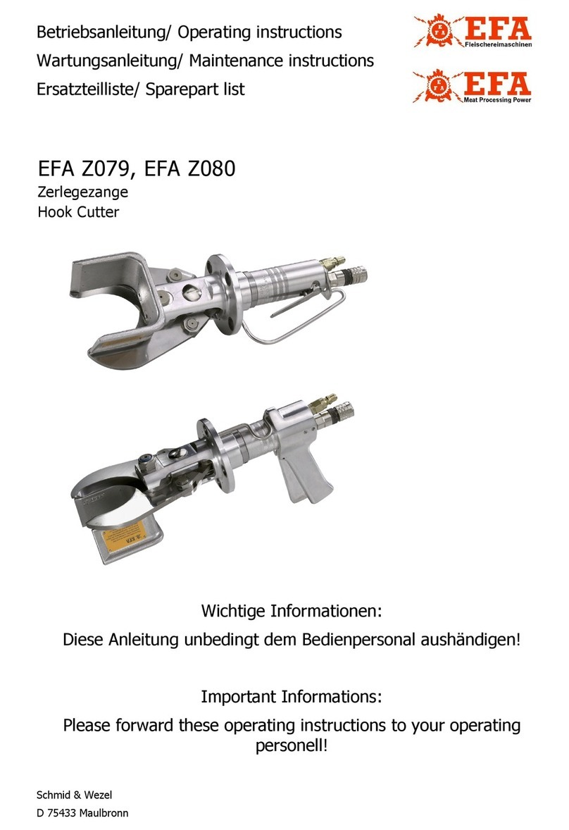
EFA Z27, EFA Z27S
Abviertelzange
Hook Cutter
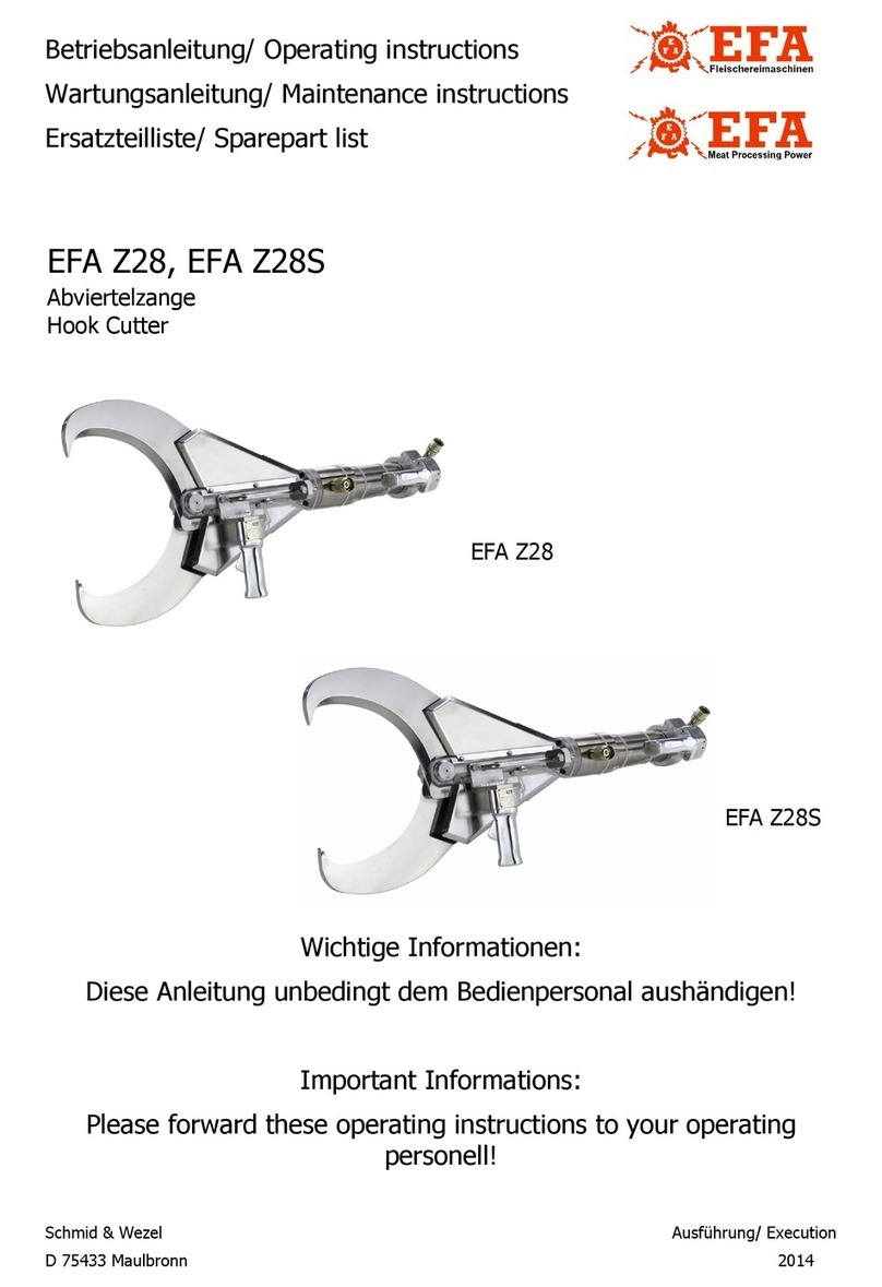
EFA Z27
EFA Z27S

Schmid & Wezel
D 75433 Maulbronn
Ausführung/ Execution
05.2004
CONTENT
1. Operation, Scope of Supply, Accessories...............................................................................1
1.1 Symbols in this Manual................................................................................................................1
1.2 Intended Use..............................................................................................................................1
1.3 Scope of Delivery........................................................................................................................1
1.4 Accessories.................................................................................................................................1
2. Safety Precautions.................................................................................................................2
2.1 General Safety Precautions ..........................................................................................................2
2.2 Conduct at the Place of Work.......................................................................................................2
3. Commissioning and operational safety .................................................................................2
3.1 Initial Operation..........................................................................................................................2
3.2 Switch Operation.........................................................................................................................3
3.3 Working with the Hook Cutter......................................................................................................3
4. Assembly................................................................................................................................3
4.1 Changing Blades .........................................................................................................................4
4.2 Valve Replacement......................................................................................................................4
4.3 Changing Pistons ........................................................................................................................4
4.4 Hydraulic Power Unit...................................................................................................................4
4.5 Adjustment of the Spring Balancer ...............................................................................................4
5. Maintenance ..........................................................................................................................5
6. Cleaning and Maintenance ....................................................................................................6
6.1 Daily Cleaning After Completing Work...........................................................................................6
6.2 Daily Maintenance of Cutter.........................................................................................................6
6.3 Extended Maintenance (after approx. 100 operating hours)............................................................6
6.4 Repair by After-Sales Service .......................................................................................................7
7. Transport and Storage...........................................................................................................7
8. Returning Products................................................................................................................7
A. Annex.....................................................................................................................................8
A.1 Technical data ............................................................................................................................8
A.2 List of spare and wear parts ........................................................................................................8
A.3 Cutter sizes ..............................................................................................................................10
A.4 Exploded diagram, Z27/ Z27S....................................................................................................11
B. Declaration of Conformity ...................................................................................................12

Schmid & Wezel
D-75433 Maulbronn
Seite / Page
1/ 12
Ausführung / Execution
05.2004
1. Operation, Scope of Supply,
Accessories
Note, read carefully!
This manual is intended for the unit operator. Keep
it in a safe place!
The hook cutter may only be used:
In a technically safe condition, for its intended
use and in accordance with the applicable safety
and accident prevention regulations.
With all the safety devices attached.
In accordance with the safety precautions.
When the operating personnel has read and
understood this manual, in particular Chapter 2
"Safety Precautions" (pg. 2) and Chapter 3
"Commissioning and operational safety" (pg. 2)
Only in this way can incorrect operation be avoided
and hazard situations correctly assessed.
Never reach into the cutting area
of the cutter to avoid the risk of
cutting off limbs!
Wear eye protection or safety gog-
gles when completing work!
1.1 Symbols in this Manual
Hazard symbol:
The greatest care and attention must be
taken here. Lack of attention can result
in an immediate risk of injury for oper-
ating personnel or third parties. Further-
more, the machine may be damaged.
Information symbol:
Texts marked with this symbol contain
important information and useful tips.
1.2 Intended Use
The cutter is designed for cutting meat containing
bone in non-frozen or partially frozen state (from
approx. 5° C).
The cutter is suitable for dismembering and cutting
work in medium-sized and large plants, both in the
meat and poultry industries.
EFA Z27: For cutting cattle
EFA Z27S: For severing pigs' heads
The device is not equipped for any other form of
use. Should the operator wish to use the device in
some other way, please consult Schmid & Wezel
GmbH & Co. (S&W) beforehand.
Use in any other way may result in a risk of acci-
dents and increased wear. The user alone is liable
for the consequences of any other form of use.
1.2.1 Residual risks
Since the cutter is intended for industrial use on an-
imal carcasses, there is a risk of injuring yourself
and, in the case of extreme misuse, of fatally injur-
ing others. Since, due to the intended use, the size
of the opening between the cutter knives cannot be
reduced, there is a risk of the neck or upper arm or
even the shoulder joint coming between the cutting
knives and the cutter then being activated. Improp-
er use of the cutter could thus lead to instant death
or to death by bleeding. Therefore, be sure to al-
ways use the machine in the proper manner.
Manufacturer's declaration:
The machine itself cannot build up any pressure.
The pressure is only built up in when connected to
an upstream pressure generator and the corre-
sponding hoses. The machine may only be put into
operation when all the requirements of the Pressure
Equipment Directive applicable to this product have
been observed.
The machine is designed for a pressure of 200 bar.
A value of can be assumed for the
pressure volume in the hook cutter and in the pres-
sure generator and hoses. The Pressure Equipment
Directive97/23/ECwiththecorrespondingdiagrams
generally applies to these elements. In view of the
robust design in respect of strength, torsional rigid-
ity and stability under static and dynamic operating
loads, however, we would refer you to Article 1.3.10
of the Pressure Equipment Directive 97/23/EC:
As the pressure constitutes no significant factor for
the design, the EFA hook cutter is not subject to the
above directive.
1.3 Scope of Delivery
Hook cutter
Operating manual
1.4 Accessories
Spring balancer
Hose unit
Aggregate
pV 240>⋅

Schmid & Wezel
D-75433 Maulbronn
Seite / Page
2/ 12
Ausführung / Execution
05.2004
Hydraulic oil
The order numbers for both the parts contained in
the scope of supply and for accessories can be
found in Annex A.2 "List of spare and wear parts"
(pg. 8).
2. Safety Precautions
2.1 General Safety Precautions
Be sure to observe the following safety pre-
cautions when working with the hook cutter.
Always disconnect the equipment from the
power supply before changing the cutting
blades or starting any installation, maintenance
and repair work.
It is assumed that all work involving operation
of the hook cutter is always completed by ade-
quately skilled operating personnel.
Instruction is provided by our specialist person-
nel.
Installation, maintenance and repair work may
only be carried out by authorised and qualified
personnel.
Hook cutters from S&W conform to the relevant
safety regulations.
2.2 Conduct at the Place of Work
1. Keep your place of work tidy. Untidiness can
lead to accidents.
2. Give consideration to environmental influences.
Ensure good lighting (min. 500 lux).
3. Keep other people away from your place of
work. Work in a concentrated and sensible man-
ner. Do not use the hook cutter when you are
unconcentrated and/or tired.
4. Keep the hook cutter in a safe place. Store the
unit in a dry place when not in use.
5. Working clothes: Do not wear any baggy clothes
or jewellery because these could be caught by
moving parts. Wear solid shoes when working.
Wear a hair net as a general rule!
6. Avoid abnormal body postures. Ensure a safe
working position and keep your balance at all
times.
7. Service your tools with care. Use only sharp and
undamaged blades so that you can work better
and safer.
8.
Use only original EFA blades. Follow the instruc-
tions given under "Changing the blades". See
also Chapter 4.1.1 "Changing the blades" (pg. 4)
.
9. Do not leave wrenches on the machine. Check
that all wrenches have been removed before
starting the equipment.
10.Use only original EFA accessories. Use of other
accessories will void the warranty. Use of other
tools or accessories may result in injury to your-
self.
11.Modifications and changes to the machine are
not permitted and exonerate S&W of any war-
ranty and liability.
3. Commissioning and opera-
tional safety
Place of work
The operator requires a working space of at least
1.5 sq. m. No other place of work should extend into
this area, as the movements with the cutter could
result in the risk of injury.
The illumination at the place of work must be at
least 500 lux.
3.1 Initial Operation
The hook cutter must be in an
"off" state when connected to the
works power network!
Important information, e.g. technical
data sheets, drawings and parts lists can
be found in Annex A.2 (pg. 8).
3.1.1 Spring balancer
The machine must always be operated in combina-
tion with a weight relief system (spring balancer).
Install this above the working area on an element
assembled higher or on the ceiling. Information on
fine adjustment of the spring balancer can be found
in Chapter 4.5 "Adjustment of the Spring Balancer"
(pg. 4).
Suspend the cutter so that it is as top-heavy as pos-
sible. The vertical position can be adjusted, if nec-
essary.
Due to the weight of approx. 24 kg, there is a risk
of injury through the unit slipping or falling down
when fixing or loosening the weight relief system.
Pay attention also that the machine does not jam
on the trigger snap or on the hook of the cutter.
Work cautiously!
When the cutter is not in use, store it so that there
is no risk of accidental contact with the blades as

Schmid & Wezel
D-75433 Maulbronn
Seite / Page
3/ 12
Ausführung / Execution
05.2004
they are sharp.
3.1.2 Hydraulic power unit
The cutting mechanism of the cutter functions hy-
draulically. Connect the cutter to an operational hy-
draulic power generator (see also the separate
operating manual for the hydraulic power unit), and
fill finely filtered hydraulic oil in the relevant
opening provided and
connect the generator unit via the terminal box
(Y-connection 3: 400 V ~, 50 Hz).
The hydraulic hoses to be used have threaded fit-
tings of different sizes and therefore cannot be con-
nected incorrectly.
3.1.3 Connecting and disconnecting the cut-
ter
The cutter is equipped with a plug connection return
flow and a coupling body feed flow. Proceed as fol-
lows:
Switch off the compressed air and actuate the
two-hand safety circuit (refer to Chapter 3.2.1
"Switching on" (pg. 3)) on the hook cutter once.
Disconnect the depressurised hydraulic hose
assembly (1 - 13), with feed flow closed, from
the hose unit.
To disconnect, release the safety locking ring on
the coupling body. To do this, turn the locking
ring until the lock is released.
The hydraulic couplers are self-locking so that no oil
escapes when they are disconnected.
Protect the coupling and plug parts
against soiling!
3.2 Switch Operation
The cutter may only be switched
on after reading this operating
manual and correct connection to
the power supply!
The hook cutter is equipped with a two-hand, safety
circuit.
3.2.1 Switching on
Hold the cutter firmly!
Actuate the front operating handle simultane-
ously with the rear operating handle to close the
cutter.
3.2.2 Switching off
Release the operating handles to open the cut-
ter
The cutting process can be interrupted or repeated
at any time.
3.3 Working with the Hook Cutter
Never reach into the cutting area
of the cutter to avoid the risk of
cutting off limbs!
Wear eye protection or safety gog-
gles when completing working!
3.3.1 Working process
The hydraulic power pack must be ready for
operation.
Hold the cutter firmly, position it correctly and
actuate the two-hand safety circuit (see Chapter
3.2 "Switch Operation" (pg. 3))
The cutting process can be carried out either with
the carcass/meat hanging or lying on the table. The
cutter operator selects the cutting area and per-
forms a quick cut by actuating the two-hand safety
circuit.
Always apply the cutter at right angles
and in the cutting area (not with the
blade tips). Otherwise the blades may
break due to overload.
Venting of the cutter is not necessary, as the air es-
capes from the venting filter of the hydraulic power
unit via the hydraulic hoses after a few actuations of
the cutter.
3.3.2 Operating safety
Hold the machine firmly with both handles.
Work very cautiously when cutting, the blades
close within 1.3 s.
Always apply the machine at right angles and in
the cutting area so that the blades do not break
in the event of overloading.
Suspend the cutter from a spring balances for
safe handling (guidance).
4. Assembly
Disconnect the machine from the
works mains power before start-
ing any assembly work!
The drawings necessary for assembly can be found

Schmid & Wezel
D-75433 Maulbronn
Seite / Page
4/ 12
Ausführung / Execution
05.2004
in Annex A.4 "Exploded diagram, Z27/ Z27S" (pg.
11)
4.1 Changing Blades
4.1.1 Changing the blades
Close the blades (36)
Switch off the hydraulic power pack and depres-
surise the system by actuating the two-hand
safety circuit once (see Annex 3.2.1 "Switching
on" (pg. 3))
Disconnect the cutter (see Chapter 3.1.3 "Con-
necting and disconnecting the cutter" (pg. 3))
Disassemble the taper sleeve (47) and force out
both bolts (44, 46) paying attention to a clean
contact of the fork (45).
Remove the hex. nut (42) with locking washer
(41) and threaded bolt (38).
Before assembling the cutter, clean the removed
parts, inspect them for wear and replace, if neces-
sary.
Grease all sliding points with EFA special grease.
4.1.2 Checking the blade clearance
In order to avoid breakage, the blades must always
be adjusted without clearance but with free move-
ment. The adjustment is made using the locking
washer (41) and hex. nut (42).
4.1.3 Blade installation
Before reassembling the cutter, clean the removed
parts, inspect them for wear and replace, if neces-
sary. Grease all sliding points with EFA special
grease.
Before securing in the forks (45), adjust the blades
(36) via the locking washer (41) and the self-locking
hex. nuts (42) so that they are clearance-free but
can move freely.
4.2 Valve Replacement
Replacing the valve parts
Remove screw (26) to release the handle (23).
Remove the snap ring (22) and pull out the
valve (17 - 21), clean the removed parts,
inspect them for wear and install again in the
reverse order.
Always replace the valve (17 - 21) together with the
snap ring (22).
4.3 Changing Pistons
Replacing the piston parts
The assembly kit must be available for this repair.
See also Annex A.2 "List of spare and wear parts"
(pg. 8).
Remove the blades (36) (see Chapter 4.1.1
"Changing the blades" (pg. 4)).
Disassemble the cutter body (27).
Loosen the cylinder barrel (13) from the guide
(1) using the hook wrench (right-hand thread).
Unbolt the housing (1) and push piston rod (7)
with piston (10) in the direction of the guide (1).
Caution:
The cylinders (1, 13) must be secured with Loctite
542!
Install piston (10) only with mounting cone and
expander sleeve - removal is possible only after
heating to 150° C.
Screw the cylinder barrel into guide (1) and
secure with Loctite 542.
Clean all the parts, check Pos. 2, 3, 10 and 11
for signs of wear and reassemble in reverse
order.
Grease all sliding points and blades (36) with EFA
special grease .
4.4 Hydraulic Power Unit
At least once a year, drain the oil filling, inspect for
soiling and replace if necessary. (See also Annex
3.1.2 "Hydraulic power unit" (pg. 3) and separate
operating manual for the hydraulic power unit).
4.5 Adjustment of the Spring Bal-
ancer
The fine adjustment of the spring balancer is effect-
ed via the PLUS/MINUS screw on its housing (see
Fig. 1).
Figure 1:Spring balancer
Turn the screw in MINUS direction until the cut-
ter is hanging freely in equilibrium (with the
spring balancer) at working height.

Schmid & Wezel
D-75433 Maulbronn
Seite / Page
5/ 12
Ausführung / Execution
05.2004
If the cutter cannot be pulled out, the spring balanc-
er is jammed and a readjustment is necessary:
Turn the screw in PLUS direction until the cutter
can be pulled out and start the fine adjustment
again (see above).
5. Maintenance
Malfunctions may occur during operation, but these
are generally relatively simple to remedy. Table 1:
"Troubleshooting" lists these malfunctions with pos-
sible causes and resulting potential remedies.
Table 1: Troubleshooting
Malfunction Possible cause Remedy
When the trigger lever is pressed,
the pump does not run and the
cutter does not close
1. Unit is not switched on. Switch on power pack
2. Power supply is incorrect. Check the electric power supply
and remedy the fault
On actuating the trigger lever, the
pump starts up but the cutter
does not close.
3. Insufficient air pressure for
switching
Set the air pressure on the power
generator to at least 5 bar with 5
m hose length
4. Control line is defective Inspect the control line and
replace, if necessary
5. Two-hand safety block is
defective Inspect the safety block and
replace, if necessary
6. Coupling connector of the
hydraulic return flow hose is not
connected properly Connect the hose correctly
7. Gaskets defective Inspect the gaskets and replace,
if necessary
8. Oil level too low Refill oil (see Chapter 3.1.2
"Hydraulic power unit" (pg. 3)
When actuating the trigger lever,
the pump starts but the cutter
closes slowly
9. Oil filter on the pump clogged Change the oil filter and oil
10. Hose coupling is loose Check the proper connection of
the hoses
Hydraulic pump too hot 11. Gear pump is defective Replace gear pump
Pumps runs, but no hydraulic
pressure in the cutter 12. Defective seals in the hydrau-
lic pump cylinder Replace the seals, replace the
pump cylinder
Handle cannot be pressed 13. Defective valve Replace valve (see Chapter 4.2
"Valve Replacement" (pg. 4))
14. Valve blocked due to soiling Clean valve (see Chapter 4.2
"Valve Replacement" (pg. 4))
Cutter does not open when han-
dle is released
15. Refer to Point 10 Refer to Point 10
16. Valve pins block, do not
return to initial position or valve
spring is broken
Clean or replace the valve or (see
Chapter 4.2 "Valve Replacement"
(pg. 4))
17. Setting of timer valve in unit
not correct Adjust the setting (see separate
operating manual or unit)
Pump does not run 18. See separate operating man-
ual for pump See separate operating manual
for pump

Schmid & Wezel
D-75433 Maulbronn
Seite / Page
6/ 12
Ausführung / Execution
05.2004
6. Cleaning and Maintenance
Disconnect the machine from the
works mains before all cleaning
and maintenance work!
6.1 Daily Cleaning After Completing
Work
Trouble-free, continuous operation can be ensured
only if the hook cutter is permanently kept in a
clean, hygienic condition. The machine should nor-
mally be disinfected before each cleaning.
Observe the applicable safety and hygiene regula-
tions (EN 1672)!
Disinfectants must not be allowed to come into di-
rect or indirect contact with foodstuffs. Rinse the
machine with clear water after disinfection.
Donot useaggressivesolvents!Do
not use steam or high-pressure
cleaners! Do not immerse the unit
in water!
6.1.1 Disinfection
Disinfect the machine during operation after every
cut with hot water (82° C).
6.1.2 Cleaning the cutter
Clean the machine after use with a cloth, brush and
warm water (40 - 55° C). Stubborn or encrusted dirt
and residue must be soaked beforehand. Clean us-
ing a cleaning agent, preferably as a foam, that is
applied to the surface to be cleaned and allowed to
work in for 15 - 20 minutes. Subsequently wash off
the dissolved soiling manually with warm water.
Recommended cleaning agents
Diversey Lever Tego 2000: Surface-active disin-
fectant.
Diversey Lever GmbH
Mallaufstr. 50-56, 68219 Mannheim
P3-topax 91: Surface-active disinfectant
Henkel-Ecolab Deutschland GmbH
Postfach 13 04 06, 40554 Düsseldorf
A cleaning plan and further details can be obtained
from the above addresses.
The above cleaning agents are only a recommenda-
tion; if other cleaning agents are used, the customer
should examine the material compatibility and com-
pliance with the hygiene regulations.
6.1.3 Lubricants and hydraulic oil
The lubricant and the hydraulic oil have to meet the
regulations for the foodstuffs sector (DIN 1672).
Recommended lubricating grease
Klübersynth UH1 14-22 (1 kg special grease in can)
Quality: H1 approval
Order No.001 365 621
Recommended hydraulic oil
Shell Risella D15 (ISO VG 10 - ISO VG 68 to DIN
51519)
Quality: H1 approval
Order No.001 365 614
6.2 Daily Maintenance of Cutter
6.2.1 Lubrication
After every cleaning, grease the pivot and sliding
points and the blades lightly with EFA Special
Grease.
6.2.2 Blade clearance
Check the blade clearance at regular intervals. In or-
der to avoid breakage, the blades must always be
adjustedwithoutclearance but withfreemovement.
If the self-locking effect of the hex. nut is no longer
assured, it must be replaced without delay. See also
Chapter 4.1 "Changing Blades" (pg. 4).
6.3 Extended Maintenance (after
approx. 100 operating hours)
6.3.1 Hydraulic power unit
Check the oil level at regular intervals and top up, if
necessary. See also Chapter 3.1.2 "Hydraulic power
unit" (pg. 3) and the separate operating manual for
the hydraulic power pack.
CAUTION! Food grade: H1 approval. Pay attention
to cleanliness! Use a filler funnel with a fine-mesh
screen (mesh width approx. 0.4 mm).
At least once a year, drain the oil filling, inspect for
soiling and replace if necessary.
The hydraulic oil is classified as a hazardous sub-
stance and must be used and disposed of according-
ly. On no account may hydraulic oil drain into the
sewage system or escape into the atmosphere.

Schmid & Wezel
D-75433 Maulbronn
Seite / Page
7/ 12
Ausführung / Execution
05.2004
6.3.2 Sharpening the blades
Incorrectly sharpened blades impair productivity
and also represent considerable risks for the user.
We have set up a sharpening service for
you in our Service department. In this
case, please contact your nearest con-
tract workshop or our parent company
directly.
If the machine is used correctly, resharpening of the
blades is not generally necessary.
If required, the blades can also be resharpened with
minimum material removal using commercially
available grinders.
Do not use force as parts could be
damaged! Only use original EFA
spare parts!
6.4 Repair by After-Sales Service
Disconnect the machine from the
works mains before starting any
repair work!
Repairs may only be carried out by specialist
personnel.
Our Service department is at your disposal for
all repair work. In the event of a repair, please
contact your nearest contract workshop or our
parent company directly.
On request, spare parts lists can be supplied to
the repair workshop with qualified specialist
staff.
After every repair, the gear units must be
repacked with grease!
7. Transport and Storage
The unit must be stored in a dry, well-ventilated
room.
The machine must be cleaned as described in Chap-
ter 6.1.2 "Cleaning the cutter" (pg. 6) and transport-
ed in dry condition.
Ensure that the unit is not damaged during trans-
port.
8. Returning Products
At the end of their useful service life, return old units
to the parent company for disposal.

Schmid & Wezel
D-75433 Maulbronn
Seite / Page
8/ 12
Ausführung / Execution
05.2004
A. Annex
A.1 Technical data
A.2 List of spare and wear parts
EFA Z27 EFA Z27S
Operating pressure 200 bar 200 bar
Closing force 26.5 kN 26.5 kN
Closing time of the jaws 1.5 s 1.5 s
Cutter opening 260 mm 186 mm
Sound pressure level (EN ISO 11688-1) < 85 dB(A) < 85 dB(A)
Hand-arm vibration (EN 28662) < 2.5 m/s2< 2.5 m/s2
Weight 24 kg 22,5 kg
Load capacity of the spring balancer 200 - 300 N 200 - 300 N
Hose length 5 m 5 m
Z27 Z27S
Fig. No. Qty. Designation Order No.
Hook cutter, ass'y. 008 008 535 008 010 524
Hydraulic cylinder assy. (1 - 13) 001 964 050
1 1 Guide, complete (with 2 - 4, 12) 001 964 046
2 1 Stripper 001 964 041
3 1 Grooved ring 001 964 039
4 1 Bushing 001 964 038
7 1 Piston rod 001 964 034
8 1 O-ring 17x2 001 312 649
9 1 Piston 001 964 032
10 1 Piston seal 001 964 040
12 1 O-ring 46x2 001 312 669
13 1
1Cylindrical tube with end section
Bracket assy. (14 - 22) 001 964 045
008 005 279
14 1 Bracket 007 005 281
15 2 Hex. head bolt 001 325 904
16 1 Pressure spring 003 003 932
17 1 Valve pin 003 005 063
18 1 O-ring 001 312 620
19 1 O-ring 001 312 627
20 1 Valve insert 003 005 055
21 1 O-ring 001 312 636
22 1 Snap ring 001 312 313
23 2 Handle assy. (with 25) 008 005 278
25 2 Taper sleeve 001 307 008
26 2 Countersunk screw 001 326 508

Schmid & Wezel
D-75433 Maulbronn
Seite / Page
9/ 12
Ausführung / Execution
05.2004
27 1 Cutter body 003 008 536
28 4 Hexagon socket head screw 002 000 275
30 2 Cover (right) 003 008 741
31 2 Cover (left) 003 008 742
32 12 Hex. head bolt 001 325 921
33 1 Bracket 003 008 526
34 2 Spring washer 001 317 003
35 2 Hex. head bolt 001 325 908
36 2 Blade complete (each with 1 piece 37 +
40) 007 008 542 007 009 046
37 4 Slide bearing 001 346 002
38 1 Stud bolt (with 39) 007 008 540
39 1 Grease nipple 001 305 802
40 2 Slide bearing 001 346 003
41 1 Washer with external tab 001 311 515
42 1 Hex. nut 001 304 630
43 2 Fork complete (each with 1 piece 37) 007 008 543
44 1 Bolt 003 008 541
45 1 Yoke 003 008 539
46 2 Bolt 003 005 083
47 3 Taper sleeve 001 307 009
Flange assy. (48 - 55) 008 005 277
48 1 Flange 003 005 056
49 1 Pressure spring 003 003 932
50 1 Valve pin 003 005 063
51 1 O-ring 001 312 620
52 1 O-ring 001 312 627
53 1 Valve insert 003 005 055
54 1 O-ring 001 312 636
55 1 Snap ring 001 312 313
56 2 Flat-head socket head cap screw 001 326 515
57 4 Male fitting 001 610 601
58 2 Flexible Rilsan hose 001 610 658
59 3 Cable tie 001 371 916
60 1 Coupling socket (with 61-62) 001 606 590
61 1 O-ring (inner) 001 312 649
61A 1 Back-up ring (inner) 001 317 801
62 1 O-ring (outer) 001 312 670
63 1 Elbow male fitting 001 606 597
64 1 Straight male fitting with shaft 001 606 598
65 1 Plug connector 001 606 591
Wear set for cutter (2 - 4, 8, 10, 12, 16,
18, 37, 40, 49, 007 899 488
Hose unit assy. (70 - 84) 008 005 181
Flow Hydraulic hose ass'y. (70 - 71) 001 606 577
70 1 Hydraulic hose 001 606 582
71 1 Plug connector 001 606 578
Return flow Hydraulic hose ass'y. (72 - 75) 001 606 579
72 1 Hydraulic hose 001 606 583
73 1 Coupling socket (74-75) 001 606 580

Schmid & Wezel
D-75433 Maulbronn
Seite / Page
10/ 12
Ausführung / Execution
05.2004
A.3 Cutter sizes
74 1 O-ring (inner) 001 312 649
74A 1 Back-up ring (inner) 001 317 801
75 1 O-ring (outer) 001 312 670
76 1 Multi-strand cable 001 610 605
77 1 Cable gland 001 325 525
78 1 Housing 003 005 068
79 2 Hex. head bolt 002 000 234
80 2 O-ring 001 312 656
81 3 Male fitting 001 610 601
82 1 Bracket 003 005 067
83 1 Gasket 003 005 396
84 5 Cable tie 001 371 913
Special Accessories
2 Hydraulic oil 20 l 001 365 614
1 Spring balancer 001 620 025
1 Grease gun 001 365 403
1 Special grease 001 365 621
1Assembly kit 007 899 668 007 899 668
1 Hook wrench 001 370 205 001 370 205
1 Face pin wrench 001 369 705 001 369 705
1 Rotating pin 001 366 005 001 366 005
1 Assembly cone 003 006 661 003 006 661
1 Expanding sleeve 003 006 662 003 006 662
Type A B C D E F
Z27 410 260 340 345 520 980
Z27S 342 186 160 165 335 795

Schmid & Wezel
D-75433 Maulbronn
Seite / Page
11/ 12
Ausführung / Execution
05.2004
A.4 Exploded diagram, Z27/ Z27S

Schmid & Wezel
D 75433 Maulbronn
Seite/ Page
12/ 12
12
Ausführung/ Execution
05.2004
B. Declaration of Conformity
EG-K O N F O R MI T Ä T S E R K L Ä R U N G
EC D E C L A R A T I O N O F C O N F O R MI T Y
Hiermit erklären wir, dass die nachfolgend bezeichneten vollständigen Maschinen aufgrund ihrer Konzipierung und Bauart der
EG-Maschinenrichtlinie 2006/42/EG und den grundlegenden Sicherheits- und Gesundheitsanforderungen entsprechen.
Bei einer nicht mit uns abgestimmten Änderung der Maschine verliert diese Erklärung ihre Gültigkeit.
We hereby declare that the following designated complete machines comply with the ECmachine directive 2006/42/ECand
meet the essential demands on health and safety on account of their conception and design.
The validity of this declaration expires when a modification to the machine is made without being coordinated with us.
CE
Bezeichnung der Maschine: Zangen
Typ EFAZ ..: 05,06,07,08,10,12,,13
14,27,27S, 28,28S, 078, 079, 080,085, 090, 140,ZR27
Antrieb Hydraulikantrieb
Angewandte Vorschriften/Richtlinien: 2006/42/EG
Angewandte A- Normen: DINEN1050
Angewandte B- Normen: DINEN294, DINEN954-1, DINEN954-2(Entwurf)
Angewandte C- Normen: EN12 984
Angewandte nationaleNormen: ---------
Machineidentification: Cutter
Type EFAZ ..: 05,06,07,08,10,12,,13
14,27,27S, 28,28S, 078, 079, 080,085, 090, 140,ZR27
Actuation Hydraulicdrive
Applied regulations/directives: 2006/42/CE
Applied A- standards: DINEN1050
Applied B- standards: DINEN294, DINEN954-1, DINEN954-2(draft)
Applied C- standards: EN12 984
Appliednational standards: ---------
Hersteller Name - Anschrift: Schmid &Wezel GmbH&Co
Manufacturer Name - Address: Maybachstrasse 2 , 75433 Maulbronn
Unterschrift: Signature: ________________________ __________________
Firma: Firma: UlrichMerkle Dr. Norbert Lay
Angaben zumUnterzeichner: Geschäftsführer Leiter Technik und Entwickelung
Details of the undersi
g
ned: Mana
g
in
g
directo
r
Head of en
g
ineerin
g
and develo
p
men
t
This manual suits for next models
1
Table of contents
Other EFA Cutter manuals

