6FormC-1601
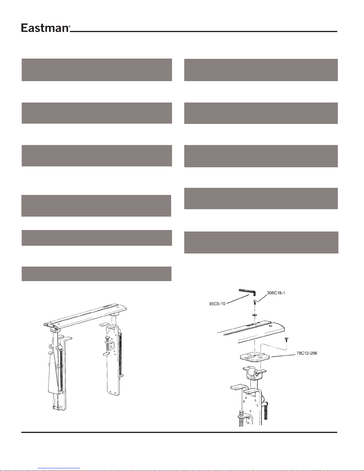
Shear Plate Adjustment
Afterreplacingshearplate,adjustangleofspringsocarbide
contactsknife edgeata 3degreeangle.Refer todiagrams
forexplanationofproperangle.
Top
View Front
View
MicroSwitchReplacement
Remove cover plate and cover insulation. Remove (2) two
switch screws and lift out microswitch being careful not to
loseswitch spacers. Remove leadsandre-solder the leads
ofthe new switch. Replace partsin reverseorder.
CAUTION
Excessivesolderingheat will damage switch.
FuseReplacement
With cover plate and cover insulation removed, fuse is vis-
ible. Liftburned out fuse out offuseholderand replace with
identicalfuse. Replacecover plate and insulation.
CAUTION
Replace only with identically rated fuse. Use of different
fusemaycauseelectricalhazardordamageelectronicparts.
Lubrication of Knife Gear
Knifegear“Z”shouldberemovedandreplacedifnecessary
orrepackedwithgreaseeverythreemonths.
Removeknifeasdescribedabove,toexposebearingretainer
plate79C12-286.Inserta#10-32x11/2"screwintocenter
ofknifeflange“X”sothatgear,bearingandknifeflangecan
beremovedasoneunit.Removethree(3)screws“W”andlift
outgearassembly.Inspectandreplacegear“Z”ifnecessary
or repack gear teeth ONLY with grease. Reassemble in
reverseordermakingsurethatbearing“Y”isseatedsquarely
beforesecuringknifeflange“X”andretainerplate.
IMPORTANT: Use of too much grease when repacking
knifegear“Z”mayresultinunduestrainon
knifemotor.
Service
Daily:
-Cleanworkarea.
-Clean track assembly.
-Cleanand lubricate guide tubeswith lightmachine oil.
-Checkbladeandsharpeningstoneforwear.
Weekly:
-Checkforanyunusualwearanddeterminewhy.
-Check entire machine for loose nuts and bolts.
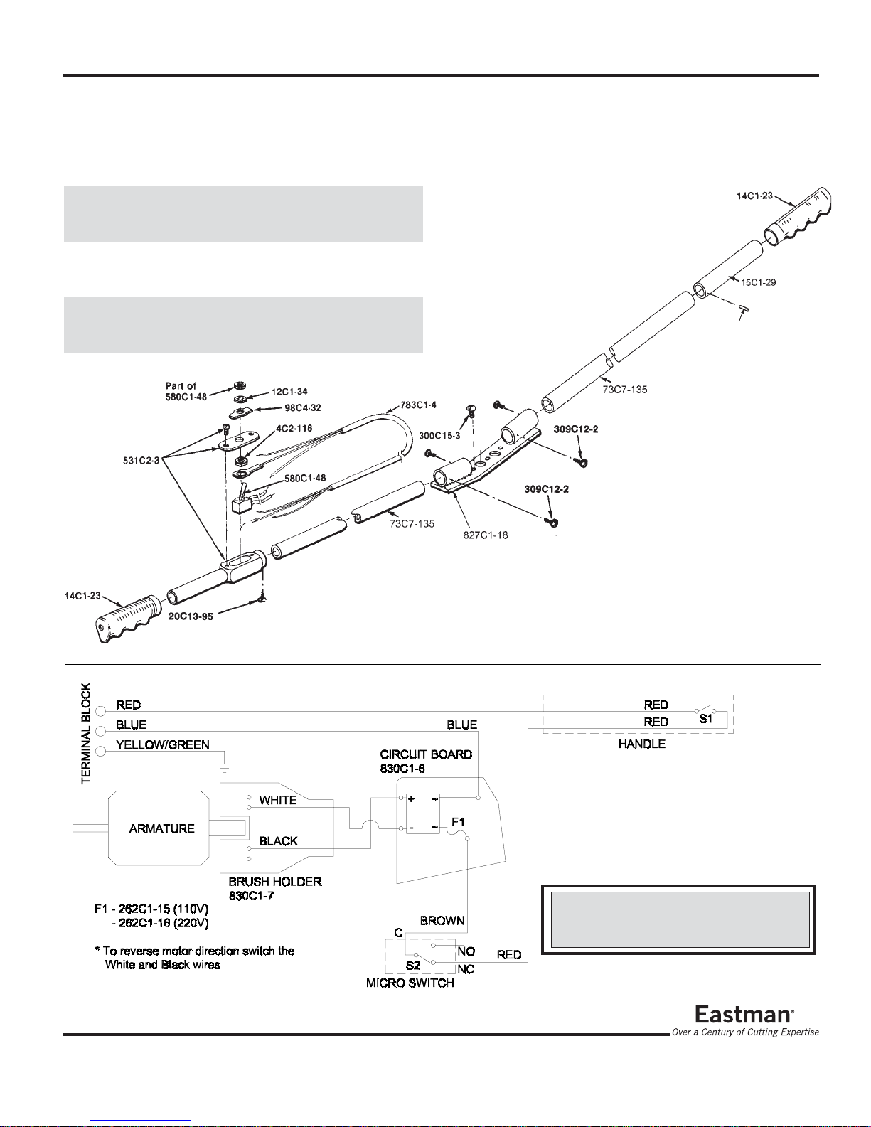
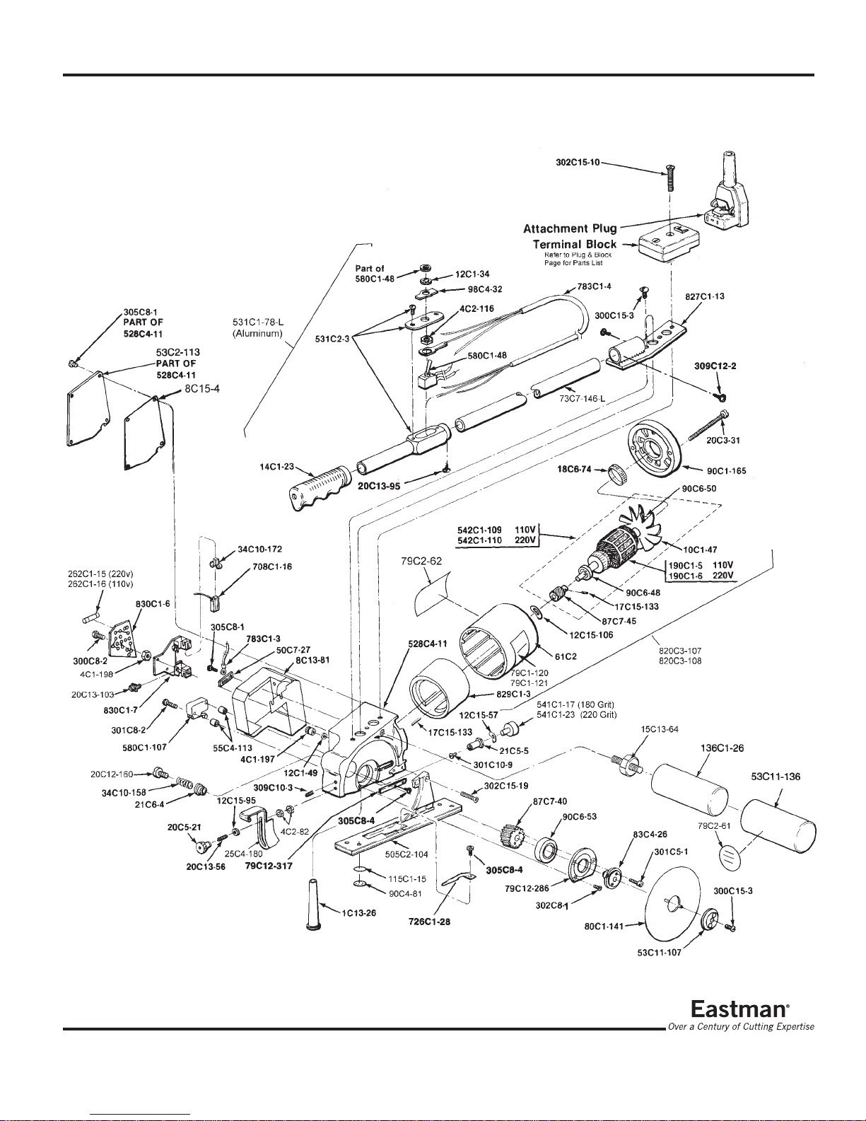
Ordering Replacement Parts
Your Eastman Falcon lV has been carefully designed to
provide many hours of trouble free operation. The
comprehensiveexplodedpartillustrationshavebeencarefully
preparedtoenableyoutoeasilyorderreplacementparts,as
required.Replacementpartsforthismachinemaybeordered
throughyournearestEastmanrepresentativeordirectlyfrom
the Eastman factory.
Sharpener Replacement
To replace sharpener stone, first remove knife blade (see
knife replacement). Insert screwdriver into slotted head of
sharpenerbutton"P"andholdhexbushing“Q”inplace. Turn
counterclockwiseandremovesharpenerbuttonandspring
“S”. Set these parts aside for later reassembly. Remove
screw “T” to separate hex bushing, spring washer “U” and
emerywheel“V”. Replaceemerywheelandreassemblein
reverseorder.Check that screw “P” is tightenedsecurely.
MotorBrushReplacement
Remove (4) four screws, cover plate and cover insulation,
being careful not to damage insulation material. Loosen
and disengage (2) two screws holding down micro switch
andliftoutswitch beingcarefulto retainthetwoswitchspac-
ers. Remove (2) two screws and carefully lift out the com-
binedassemblyofthemotorbrushcardcircuitboard. Move-
ment of the parts will be restricted by wires but have ad-
equate length to work without disconnecting. Loosen (2)
twobrush screws and remove the motorbrushpigtailsfrom
underthefasteners. Turnbrushcardoverandslidebrushes
outofguides.
When inserting new brushes, bevel corner at wire pigtail
must face slot in brush holder. Pigtail runs through slot to
screw fastener. Wrap pigtails around screw fasteners and
tighten. Turn assembly back to its original position. With
yourfingers,separatebrushes enoughtofitaroundcommu-
tatorbarsand begin working the assembly inside cavityin-
sulation. Continue working assembly down until it is flat to
inside of standard and brushes snap into position around
commutator. Replace (2) two screws holding down circuit
board and motor brush card. Replace switch spacers and
switchand secure with(2)twoscrews. Replace cover insu-
lationandcoverandfasten with (4) four screws.