EFD 1000XL User manual

Operating Guide
1000 Series Dispensers
®
A NORDSON COMPANY
In the US: 800-556-3484 In the UK: 0800 585733 In Mexico: 001-800-556-3484
1000XL 1000D
•

The 1000 Series dispensers provide years of trouble-free, produc-
tive service. This Operating Guide will help you maximize the
usefulness of your new dispenser.
Pleasespendafewminutestobecomefamiliarwiththecontrolsand
features of your new dispenser. Follow our recommended testing
procedures. Reviewthehelpfulinformationwehaveincludedbased
on over 30 years of industrial dispensing experience.
Most questions you will have are answered in this Guide. However,
ifyouneedassistance,pleasedonothesitatetocontactEFDoryour
authorized EFD distributor.
In the US, call 800-556-3484.
In Mexico, call 001-800-556-3484.
In the UK, ring free 0800 585733.
Introduction
The EFD Pledge
We pledge that you will be completely satisfied with our products.
We endeavor to ensure that every EFD product is produced to our
no-compromise quality standards.
If you feel that you are not receiving all the support you require,
orifyouhaveanyquestionsorcomments,Iinviteyoutowriteorcall
me personally.
Our goal is to build not only the finest equipment and components,
but also to build long-term customer relationships founded on
superb quality, service, value and trust. John Carter, President
☎

Getting Started ............................................................................. 4
Specifications
First Steps .................................................................................... 5
Unpacking the Dispenser and Activating your Ten Year No-fault Warranty
1000XL - Hookup ...................................................................... 6-7
1000XL - Setup for Testing ....................................................... 8-9
1000D - Hookup .................................................................... 10-11
1000D - Setup for Testing ..................................................... 12-13
Testing the 1000 Series Dispensers ..................................... 14-15
Making Timed Deposits
Changing Deposit Size
Drawing Stripes
ULTRA Dispensing System................................................... 16-17
How to Use the Vacuum Control........................................... 18-19
1000XL only
Loading the Barrel Reservoirs............................................... 20-21
Now, Test Your Fluid.................................................................. 22
Troubleshooting ......................................................................... 23
1000XL and 1000D Schematic & Parts...................................... 24
1000 Series Programmable Timer ............................................. 25
Suggestions & Reminders.......................................................... 26
Components Reorder................................................................. 27
Ten Year No-fault Warranty ....................................................... 28
Meets applicable CSA and CE requirements.
Reference CSA LR File Number 84105
Contents
This manual is for the express and sole use of EFD
dispenserpurchasers and users,andnoportionof this
manual may be reproduced in any form.
EFD, ULTRA System, LV Barrier, SmoothFlow,
ZeroDraft, SafetyLok, SnapLok and DispenStand are
trademarks of EFD Inc. ©2004 EFD Inc.

We have organized this Guide to provide setup and testing proce-
dures for the 1000XL and 1000D dispensers.
If you have the 1000XL, first review pages 6 - 9 which illustrate how
to hook up the dispenser and what the controls do.
For the 1000D, review pages 10 - 13.
Next, pages 14 - 15 show how to dispense the thick, paste-like test
material included in the Test Kit. These instructions are common to
both 1000 Series dispensers.
Finally, pages 18 - 19 illustrate how to dispense low-viscosity liquid
using the vacuum control provided on the 1000XL.
The rest of the information in this Guide applies to both of the 1000
Series dispensers.
1000 Series Specifications
Input voltage: Selectable
100/120/220 VAC
50/60 Hz 16/13 VA
Internal voltage: 24 VDC
Foot-pedal voltage: 9 VDC
Air input: 80 to 100 psi
(5.5 to 6.9 bar)
Air output: 0 to 100 psi
(0 to 6.9 bar)
Cycle rate: > 600/minute
Time repeat: ±0.1%
Initiation: maintained or momentary
TimeRange: programmable(seconds)
0.005 to 0.04 sec.
0.01 to 1.0 sec.
0.1 to 10 sec.
0.2 to 20 sec.
0.3 to 31 sec.
1000XL
10⅜x 8½x 2⅝ 5 lb 12 oz
26.4 x 21.6 x 6.7 cm 2.63 kg
1000D
8⅝x 8½x 2⅝ 4 lb 12 oz
21.9 x 21.6 x 6.7 cm 2.18 kg
Getting Started

First: Unpackanduse the checklist enclosed with the Dispenser Kit
to identify all items. If there is any discrepancy, please call us
immediately.
Second: Powerandcompressedplantairshouldbeavailablewhere
thedispenseristobesetup. Airpressureshouldbebetween80and
100 psi (5.5 to 6.9 bar). (Bottled nitrogen can be used.) If you are
notusing an EFD five-micronfilterregulator #2000F755, be certain
your plant air is properly filtered and dry.
Check voltage label to be certain it agrees with the available power.
Third: Now is a good time to ACTIVATE your extended Ten Year
No-fault Warranty. Please fill in and return the postage-paid
Warrantycard. Or,ifyouprefer,calltheappropriatetoll-freenumber
listed below, provide the serial number of your dispenser and
respond to a few short questions.
In the US, call 800-556-3484.
In Mexico, call 001-800-556-3484.
In the UK, ring free 0800 585733.
☎
First Steps

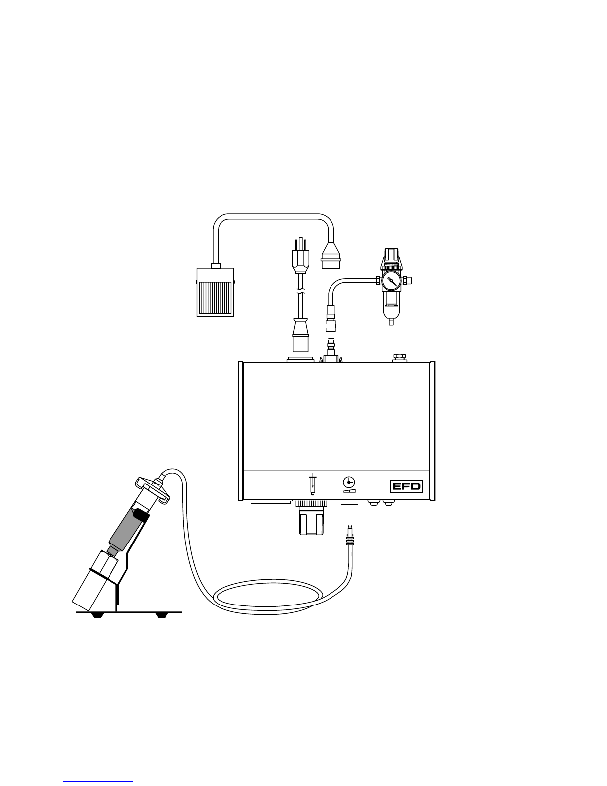
❻
❶
❺
Check voltage label
on dispenser
Plant air, 125 psi maximum to
regulator. Output from regulator
should be a minimum of 80 psi,
maximum of 100 psi.
❷
❸
❹
Blue
test fluid Male quick-connect,
insert and twist to lock
❼
Power
cord
Air input
hose
Foot pedal
assembly
Adapter
assembly 1000XL

1000XL
1000XL -- Hookup
❶Connecttheairinputhosetoaplantairsource. Setplantairsupply
within 80 to 100 psi (5.5 to 6.9 bar). Where required, use an EFD
five-micron filter regulator #2000F755 (see Warranty).
❷Attachtheairinputhosecouplingtothedispenser. Pullbackmetal
ring to attach to dispenser.
❸Plug in the polarized foot pedal connector.
❹Checkthevoltagelabelontheinputvoltageselectorcartridge. To
change the voltage, remove the voltage selector from the car-
tridge,rotateitandpositionthecorrectvoltagetoshowthroughthe
cartridge window. Replace the cartridge into the power cord
receptacle and insure that both sides snap securely into position.
Install the power cord.
❺Attach the 10cc barrel pre-filled with blue, nontoxic test fluid
(included with the dispenser) to the 10cc adapter head.
❻Takethe10ccadapterassembly(#5150ontheadapterhead)and
inserttheblack,malequick-connectintotheairoutputfittingonthe
frontpanelandturnclockwisetolock. Placethebarrelinthebarrel
stand.
❼Duringtheinitialtesting,youwillnotusethevacuumcontrol. Keep
this control shut off (turned completely clockwise—do not force).
220
120
100
Spare fuse
Voltage value
Cartridge window
(check voltage indicated)

CONTROLS and CONNECTIONS
5
4
Voltage selector and
fuse cartridge
Air input
Vacuum transducer
air exhaust port
Cover screw
Power input
receptacle
Barrel
vacuum control Vacuum gauge
Air output
quick-connect Power
switch
21
Air pressure
regulator
3
6
Timer
bypass
7
Time
controlAir gauge Cycle LED
220

1000XL
1000XL -- Setup for Testing
Power switch 6should be off.
The amount of material dispensed each cycle depends on the
combination of air pressure, time of air pulse, viscosity of material
and dispensing tip size.
Thefirststepistoremovethetipcapfromthepre-filledbarrelofblue
test material (twist and pull). Replace it with an 18 gage (green)
tapered dispensing tip. Press the tip on and twist clockwise to lock.
Pulloutairpressureregulatorknob1untilit"clicks"intotheunlocked
position. Turnclockwisetoadjusttheairpressureto30psi(2.1bar)
for the initial tests.
Always set the pressure desired by turning the air regulator knob 1
clockwise. To reduce the pressure, turn the knob counterclockwise
until the air gauge 2reads a lower pressure than desired. Then
increase and stop at desired pressure. Push knob in to lock.
Set the time control 3to #7. Dispense cycle time increases from
0.01 second minimum to 1.0 second as knob is turned clockwise.
Be sure vacuum control 4is shut off. In the initial tests, the vacuum
pressure gauge 5will indicate zero pressure. You may notice the
needle on this gauge (when turned off) will jump slightly after each
cycle. This is normal.
Press power switch 6to turn on the dispenser. It will light green.
Press timer bypass switch 7. It will light yellow. In this operation
mode, the timer will be bypassed to fill the dispensing tip before you
begintesting. Acontinuousflowofmaterialwilloccuraslongasthe
foot pedal is pressed.
Please continue to page 14 for test procedures.
❶
Plant air, 125 psi maximum to
regulator. Output from regulator
should be a minimum of 80 psi,
maximum of 100 psi.
❷
❺
Check voltage label
on dispenser
❸
❻
Blue
test fluid
❹
Male quick-connect,
insert and twist to lock
Power
cord
Air input
hose
Foot pedal
assembly
Adapter
assembly
1000D

1000D -- Hookup
❶Connecttheairinputhosetoaplantairsource. Setplantairsupply
within 80 to 100 psi (5.5 to 6.9 bar). Where required, use an EFD
five-micron filter regulator #2000F755 (see Warranty).
❷Attachtheairinputhosecouplingtothedispenser. Pullbackmetal
ring to attach to dispenser.
❸Plug in the polarized foot pedal connector.
❹Checkthevoltagelabelontheinputvoltageselectorcartridge. To
change the voltage, remove the voltage selector from the car-
tridge,rotateitandpositionthecorrectvoltagetoshowthroughthe
cartridge window. Replace the cartridge into the power cord
receptacle and insure that both sides snap securely into position.
Install the power cord.
❺Attach the 10cc barrel pre-filled with blue, nontoxic test fluid
(included with the dispenser) to the 10cc adapter head.
❻Takethe10ccadapterassembly(#5150ontheadapterhead)and
inserttheblack,malequick-connectintotheairoutputfittingonthe
frontpanelandturnclockwisetolock. Placethebarrelinthebarrel
stand.
1000D
220
120
100
Spare fuse
Voltage value
Cartridge window
(check voltage indicated)

CONTROLS and CONNECTIONS
Cover screw
Air output
quick-connect Power
switch
21
Air pressure
regulator
3
4
Timer bypass
5
Time
controlAir gauge Cycle
LED
220
Air input
Solenoid Power input
receptacle
Foot pedal
receptacle Voltage selector
and fuse cartridge

Power switch 4should be off.
The amount of material dispensed each cycle depends on the
combination of air pressure, time of air pulse, viscosity of material
and dispensing tip size.
Thefirststepistoremovethetipcapfromthepre-filledbarrelofblue
test material (twist and pull). Replace it with the 18 gage (green)
tapered dispensing tip. Press the tip on and twist to lock.
Pulloutairpressureregulatorknob1untilit"clicks"intotheunlocked
position. Turnclockwisetoadjusttheairpressureto30psi(2.1bar)
for the initial tests.
Always set the pressure desired by turning the air regulator knob 1
clockwise. To reduce the pressure, turn the knob counterclockwise
until the air gauge 2reads a lower pressure than desired. Then
increase and stop at desired pressure. Push knob in to lock.
Setthetimecontrol 3to#7. Dispensecycletimeincreasesfrom0.01
second minimum to 1.0 second as knob is turned clockwise.
Press power switch 4to turn on the dispenser. It will light green.
Press timer bypass switch 5. It will light yellow. In this operation
mode, the timer will be bypassed to fill the dispensing tip before you
begintesting. Acontinuousflowofmaterialwilloccuraslongasthe
foot pedal is pressed.
Please continue to page 14 for test procedures.
1000D -- Setup for Testing
1000D

Making Timed Deposits
Youarenowreadytotestthepre-filled,nontoxic,bluetestfluid. This
material is representative of thick, non-leveling fluids like sealants,
pastes or greases.
Check your initial settings:
A) Air gauge reads 30 psi
B) Timer is set at #7
C) Green tapered tip is on the test barrel
D) Power and timer bypass switches are on.
Holding the barrel as shown, rest the tip on a piece of paper. Press
the foot pedal until the tip fills and some fluid is pushed out onto the
paper. Repeat this whenever you change to a new tip.
With the tip filled, turn the timer bypass switch off (yellow light out).
UsetheDotTestsheetsupplied,andpressthefootpedaltoactivate
the timer. Check the dot size. Press the foot pedal again and note
the size consistency.
Remember—When the yellow timer bypass switch is on, a continu-
ous flow of material will occur as long as the foot pedal is pressed.
The yellow light must be off to make timed deposits.
Trydifferentpressuresettings. Continuetoexperimentbyreplacing
the green tip with the blue (22 gage) tapered tip included in the Dot
Test Kit. Note the effects of air pressure and tip size on the deposit.
Correct angle for consistent deposits.
Remember-alwaysbringthetipin
contact with the work surface at
the illustrated angle. After the tip
isin position, pressthefootpedal.
Release pedal and remove tip by
lifting straight up.
Testing the 1000 Series Dispensers
Timer
Pressure
2
30
7
6
8
45°
80°

Changing Deposit Size, Drawing Stripes
The dot size is determined by the tip diameter, the air pressure
output setting and the pulse time. For large dots, use a large tip,
higher pressure and more time. Normally, you want to use as short
a time pulse as possible. To increase the dot size, slightly increase
the air pressure output, or increase the tip size, or both.
Use the convenient Dot Test sheet included.
Dot Test with Green Tapered Tip
First, follow the settings illustrated on the left, and you will get dots
about the sizes shown. Try other times and pressures to see how
easy it is to get just the dot size you want.
Dot Test with Blue Tapered Tip
These tests show the effect of using a smaller diameter tip.
Replacethegreentipwiththeblue(22 gage) tapered tip. Now, turn
on the timer bypass switch and press the foot pedal to fill the tip.
Then,turnoffthetimerbypassswitch(yellowlightout)andpressthe
foot pedal.
Making Stripes
Keep the settings at Test G (shown to the left) and turn on the timer
bypass switch (yellow light on). With the tip in contact with the test
sheet, press and hold down the foot pedal while drawing a line for
beading or striping.
Blue Tip Settings
Test Pressure Time Dot Size
F 30 psi #6
G 20 psi #6
H 20 psi #3
I 15 psi #3
J 10 psi #3
Green Tip Settings
Test Pressure Time Dot Size
A 30 psi #7
B 20 psi #7
C 20 psi #3
D 15 psi #3
E 10 psi #3

Ifyoudispensethickfluids,severalproblemsmay
occur. First, the repetitive air cycles can bore
tunnels through non-leveling fluids, causing
spitting and inconsistent deposits. Second, thick
fluids contain trapped air that leads to drooling
and oozing.
These problems are eliminated by using the
SmoothFlow™piston. That's because the white
pistonspreventtunnelingbyprovidingabarrierto
the pulsed-air cycles, and prevent oozing by
responding to the pressure of trapped air with a
slight suck-back movement after the dispense
cycle.
The white piston is used for most fluids.
However, if you are applying RTV silicone and
findthatthepistonbouncesandcausesstringing,
switch to the orange, flat wall piston.
The SmoothFlow™pistons make barrel filling
easier, too. As you load the fluid in, air is trapped
in the bottom and throughout the fluid. Simply
insert a SmoothFlow™piston and gently press
down on the fluid as far as possible. This action
forcesoutmostoftheairandresultsinconsistent
deposits.
Advanced Dispensing System
For Thick Fluids
Air Pressure
OFF
Air Pressure
ON
No drip
or ooze.
TM

For Thin Fluids
Fumes
cannot
escape.
SmoothFlow™piston
prevents fluid backflow.
For Watery-thin Fluids
Blue LV Barrier™for
improved control of
very low viscosity
fluids.
Note: If you choose not to use the piston,
please refer to page 19 for instructions.
Ifyouuselowtomediumviscosityfluids,thewhite
SmoothFlow™piston has several advantages.
First, vacuum adjustment is much less sensitive.
Second, the piston prevents fumes from the fluid
beingexhaustedintotheworkenvironment. Third,
the piston prevents fluid backflow into the dis-
penser if the barrel is inadvertently turned upside
down. Fourth,usingthepiston makesiteasy and
safe to change tips without dripping.
Note: Ifyouusewatery-thinfluidssuchassolvents,
cyanoacrylatesandanaerobics,specifytheULTRA
System™withtheblueLVBarrier™
. Availableonly
in 10cc size.

How to Use the Vacuum Control (1000XL only)
Insert
SmoothFlow™
piston.
Remove
orange
end cap.
Remove
tip cap.
The vacuum control allows low viscosity fluids, even water, to be
consistentlydispensedwithoutdrippingbetweencycles. Thevacuum
exerts a negative pressure on the fluid in the barrel and prevents
dripping.
For these tests, you will use the test barrel with the clear fluid.
1. Whileholdingthebarreluprightinonehand,removetheorange
end cap and insert the white SmoothFlow™piston. Carefully
press the piston down to contact the liquid.
Be sure to push it far enough to remove all air, but not into the
fluid,sincethiswillforcethefluidupalongthesidesofthepiston.
2. Attachthebarreltothe10ccadapter. Snapthesafetycliptightly
closed to prevent any dripping or bubbling. Remove the tip cap
and attach the 25 gage (red) tip.
3. Setairpressureat 5psiandtimerto#5,thenturnontimerbypass.
4. With the barrel pointing downward over a container, press the
foot pedal to fill the tip.
5. Turn off the timer bypass switch (yellow light out).
6. If a drop begins to form at the end of the tip, slowly turn the
vacuum control knob counterclockwise to stop the drop from
growing. Wipethetipandslowlyadjustvacuum. Normally,only
1 to 2 psi of vacuum pressure is necessary.
7. Takethebarrelandplacethetiponthetestsheet. Pressthefoot
pedalandrelease. Check thedeposit. Increase ordecreaseby
adjusting pressure or time.

If you choose not to use the piston, please follow these instruc-
tions carefully:
1. While holding the barrel upright in one hand, twist on an
orange tip cap. Using the small funnel supplied, fill about
2/3 full with your liquid.
2. Openthesafetyclipandattachthebarreltothe10ccadapter.
3. Close the safety clip as tight as possible.
4. Increase vacuum by turning vacuum control knob counter-
clockwise and set to 1.5 on the vacuum pressure gauge.
5. Then, without tipping the barrel upside down, remove the tip
cap and attach the 25 gage (red) tip.
6. Open the safety clip. Your material may begin to bubble.
Reduce vacuum by turning vacuum control knob clockwise.
7. If a drop begins to form at the end of the tip, slowly turn the
vacuumcontrol knob counterclockwise to stop the drop from
growing. Wipe the tip and adjust vacuum as necessary.
Now the fluid is in proper balance. It does not bubble or drip.
Repeat tests as before, keeping the air pressure low and adjust-
ing the time for different deposit sizes. Contact EFD if you have
any questions.
In the US, call 800-556-3484.
In Mexico, call 001-800-556-3484.
In the UK, ring free 0800 585733.
☎
Do not tip the barrel upside down
or lay flat. This will cause the
liquid to run into the dispenser.
When changing tips
or attaching a tip cap,
snap the safety clip
completely closed to
prevent any dripping
or bubbling.
Three things to remember
If you do not use the piston when
dispensing thin fluids:
Use an EFD filter trap (#1000FLT-Y).
This filter trap will impede the flow
should the low viscosity liquid be
sucked back towards the dispenser.
Open
Closed

Loading the Barrel Reservoirs
Caution:Donotcompletelyfillbarrels.Theoptimumfillisamaximum
2/3 of the barrel capacity and 1/2 of the barrel capacity when using
the LV Barrier™
.
If the fluid you are dispensing is pourable, take the barrel, twist on a
tipcap andpour yourfluidin. Ifappropriate, inserttheSmoothFlow™
piston(seepage13). Carefullypressthepistondownuntilitcontacts
the fluid. The barrel is now ready for use.
If you are dispensing solvents, cyanoacrylates or anaerobics, use
theLVBarrier™
. Placebarrierinthetopofthebarrelreservoir. Allow
air between barrier and fluid. Do not contact the barrier to the fluid.
If your fluid is thick or non-leveling, you can spoon it into the barrel
withaspatula. Or,ifthefluidcomespackedina1/10galloncartridge,
try loading the barrel with a caulking gun. Then, press in the
SmoothFlow™pistontomovethefluidtothebottomofthebarreland
to remove trapped air.
2/3
Maximum
Fill
White
SmoothFlow™
piston.
LV Barrier™
Fill procedure for
watery-thin fluids.
1/2 maximum fill
Fill procedure with
caulking gun. Air
Fill procedure for
pourable fluids.
This manual suits for next models
1
Table of contents
Other EFD Dispenser manuals


Popular Dispenser manuals by other brands

Follett
Follett C125A Installation, operation and service manual

Bunn
Bunn FMD-1 Cleaning instructions

Hampton Research
Hampton Research HR8-170 user guide

Franke
Franke RODX625 Installation and operating instructions

Murdock
Murdock A152.8FG-BF3 Series Installation & maintenance instructions

Tach-It
Tach-It SH-402TR user manual

Bunn
Bunn BUNN-O-MATIC ULTRA-1 Installation & operating guide

Harvia
Harvia AUTODOSE Instructions for installation and use

BOWMAN
BOWMAN BD216-0012 manual

MT
MT columbia aqua FC-750-SOBREMESA-RO Service manual

Sartorius
Sartorius rLine 5-200ul LS Technical user's manual

Kingnode
Kingnode E-404 Series operating manual


