EFD Ultra 325TT User manual

™
User’s Guide
Ultra
®
TT Automation Series
This is an EFD®publication, which is protected by copyright.No part of this document may be photocopied,
reproduced, or translated to another language without the prior written consent of EFD.The information
contained in this publication is subject to change without notice.
The Wave Design is a trademark of Nordson Corporation. Palm,Palm OS, Zire andTungsten are trademarks of
Palm, Inc.Clie is a trademark of Sony Corporation. Bluetooth is a trademark of Bluetooth SIG,Inc. Socket is a
trademark of Socket Communications, Inc.
A NORDSON COMPANY
For EFD sales and service in over 30 countries,
contact EFD or go to www.efd-inc.com/contact
USA & Canada: 800-556-3484 or +1-401-434-1680
Europe: 0800 585733 or +44 (0) 1582 666334
Asia: +86 (21) 5854 2345
[email protected] www.efd-inc.com/xyz
©2007 Nordson Corporation 031907 v1.2

®
A NORDSON COMPANY
Ultra TT User's Guide
Version 1.2
Introduction
The Ultra TT Automation Series System is a batch process, semi-automatic, time-pressure
dispensing system with fully integrated closed-loop positioning functions. The system ensures
repeatability in both critical positioning and timing operations, thus ensuring a more consistent fluid
deposit and a higher quality product.
Please spend a few minutes to become familiar with this guide before operating your new Ultra TT
system. Follow our recommended teaching and operating procedures. Use the template provided
to help you create programs that incorporates different core dispensing functions. Review the
helpful information we have included from over 30 years of industrial dispensing experience.
Most questions you will have are answered in this guide. However if you need further assistance,
please do not hesitate to contact EFD®or your authorized distributor.
www.efd-inc.com/xyz
☎
US & Canada, call 800-556-3484
In Mexico, call 001-800-556-3484
In the UK, ring free 0800 585733
The EFD Pledge
We pledge that you will be completely satisfied with our products. We endeavor to ensure that
every EFD product is produced to our no-compromise quality standards.
If you feel that you are not receiving all the support you require, or if you have any questions or
comments, I invite you to write or call me personally.
Our goal is to build not only the finest equipment and components, but also to build long-term
customer relationships founded on superb quality, service, value and trust.
2
Peter Lambert, President
+1 (401) 434-1680

®
A NORDSON COMPANY
Ultra TT User's Guide
Version 1.2
3
CONTENTS
Safety Warnings . . . . . . . . . . . . . . . . . . . . . . . . . . . . . . . . . . . . . . . . . . . . . . . . . . . . 5-7
i. Log-out Tag-out Procedures . . . . . . . . . . . . . . . . . . . . . . . . . . . . . . . . . . 7
ii. Operator Hazard Training . . . . . . . . . . . . . . . . . . . . . . . . . . . . . . . . . . . . . . 8
Specifications
Figure 1: Dimensions of Ultra 325TT . . . . . . . . . . . . . . . . . . . . . . . . . . . . . . . 9-11
Figure 2: Dimensions of Ultra 525TT . . . . . . . . . . . . . . . . . . . . . . . . . . . . . . . 9-11
Shipping Contents . . . . . . . . . . . . . . . . . . . . . . . . . . . . . . . . . . . . . . . . . . . . . . . . . . . . . . . . . . . 12
Warranty . . . . . . . . . . . . . . . . . . . . . . . . . . . . . . . . . . . . . . . . . . . . . . . . . . . . . . . . . . . . . . . . . . . . . . 12
1 Getting Started
1.1 System Features . . . . . . . . . . . . . . . . . . . . . . . . . . . . . . . . . . . . . . . . . . . . . 13
1.1.1 Front Panel . . . . . . . . . . . . . . . . . . . . . . . . . . . . . . . . . . . . . . . . . . . 14
1.1.2 Back Panel . . . . . . . . . . . . . . . . . . . . . . . . . . . . . . . . . . . . . . . . . . . 15
1.2 Machine Movements . . . . . . . . . . . . . . . . . . . . . . . . . . . . . . . . . . . . . . . . . 16
1.3 A Typical Operation . . . . . . . . . . . . . . . . . . . . . . . . . . . . . . . . . . . . . . . . . . .16
2Setup
2.1 Preparing the work area . . . . . . . . . . . . . . . . . . . . . . . . . . . . . . . . . . . . . .17
2.2 Main Air & Electrical . . . . . . . . . . . . . . . . . . . . . . . . . . . . . . . . . . . . . . . . . .17
2.3 Mounting Work-holding Fixture . . . . . . . . . . . . . . . . . . . . . . . . . . . . . . .18
2.4 Connections on the Z-head . . . . . . . . . . . . . . . . . . . . . . . . . . . . . . .18-19
2.5 Mounting Valve or Syringe barrel . . . . . . . . . . . . . . . . . . . . . . . . . . . . . 20
2.5.1 Syringe barrel . . . . . . . . . . . . . . . . . . . . . . . . . . . . . . . . . . . . . . . . 21
2.5.2 Single air input valve . . . . . . . . . . . . . . . . . . . . . . . . . . . . . . . . . 22
2.5.3 Multi air input valve . . . . . . . . . . . . . . . . . . . . . . . . . . . . . . . . . . 23
2.5.4 Electric auger valve . . . . . . . . . . . . . . . . . . . . . . . . . . . . . . . . . . 24
2.6 Mounting Laser Pointer . . . . . . . . . . . . . . . . . . . . . . . . . . . . . . . . . . . . . . 25
3PDA
. . . . . . . . . . . . . . . . . . . . . . . . . . . . . . . . . . . . . . . . . . . . . . . . . . . . . . . . . . . . . . 26-27
4 System Configuration
4.1 Valve Selection . . . . . . . . . . . . . . . . . . . . . . . . . . . . . . . . . . . . . . . . . . . . . . . 28
4.1.1 Valve #1 . . . . . . . . . . . . . . . . . . . . . . . . . . . . . . . . . . . . . . . . . . . . . . 29
4.1.1.1 Teaching Tip to Probe Offset . . . . . . . . . . . . . . . . . 30
4.1.2 Toggle Valve . . . . . . . . . . . . . . . . . . . . . . . . . . . . . . . . . . . . . . . . . . 31
4.1.2.1 Configuring Toggle . . . . . . . . . . . . . . . . . . . . . . . . 31-32
4.2 Units . . . . . . . . . . . . . . . . . . . . . . . . . . . . . . . . . . . . . . . . . . . . . . . . . . . . . . . .32
4.3 Height Sensor . . . . . . . . . . . . . . . . . . . . . . . . . . . . . . . . . . . . . . . . . . . . . . . . .33
4.4 Park Location . . . . . . . . . . . . . . . . . . . . . . . . . . . . . . . . . . . . . . . . . . . . . . . . .34
4.5 Purge Valve #1 . . . . . . . . . . . . . . . . . . . . . . . . . . . . . . . . . . . . . . . . . . . . . . . .34
4.6 Purge Toggle . . . . . . . . . . . . . . . . . . . . . . . . . . . . . . . . . . . . . . . . . . . . . . . . . .35
4.7 Safe Z . . . . . . . . . . . . . . . . . . . . . . . . . . . . . . . . . . . . . . . . . . . . . . . . . . . . . . . .35
5 Programming
5.1 Creating a New Program . . . . . . . . . . . . . . . . . . . . . . . . . . . . . . . . . .36-37
5.2 Teaching Dispensing Points . . . . . . . . . . . . . . . . . . . . . . . . . . . . . . . . . . .37
5.3 Teaching a Dot . . . . . . . . . . . . . . . . . . . . . . . . . . . . . . . . . . . . . . . . . . . . . . . .38

®
A NORDSON COMPANY
Ultra TT User's Guide
Version 1.2
4
5.4 Teaching a Continuous Path . . . . . . . . . . . . . . . . . . . . . . . . . . . . . . . . . .39
5.4.1 CP Line . . . . . . . . . . . . . . . . . . . . . . . . . . . . . . . . . . . . . . . . . . . .39-40
5.4.2 Arc . . . . . . . . . . . . . . . . . . . . . . . . . . . . . . . . . . . . . . . . . . . . . . . . .40-41
5.4.3 Circle . . . . . . . . . . . . . . . . . . . . . . . . . . . . . . . . . . . . . . . . . . . . . . . . . .41
5.4.4 Irregular Continuous Path . . . . . . . . . . . . . . . . . . . . . . . . . . . . .42
5.5 Height Sense . . . . . . . . . . . . . . . . . . . . . . . . . . . . . . . . . . . . . . . . . . . . . .42-43
5.6 Stepping & Repeating (Regular Intervals) . . . . . . . . . . . . . . . . .44-45
5.7 Inserting a DO Program Instruction . . . . . . . . . . . . . . . . . . . . . . .45-46
5.8 Inserting an OUTPUT Instruction . . . . . . . . . . . . . . . . . . . . . . . . . . . . .47
5.9 Executing a Download . . . . . . . . . . . . . . . . . . . . . . . . . . . . . . . . . . . . . . . .48
6 Operational Features
6.1 Downloading a Program . . . . . . . . . . . . . . . . . . . . . . . . . . . . . . . . . . . . . .49
6.2 Running a Program . . . . . . . . . . . . . . . . . . . . . . . . . . . . . . . . . . . . . . . . . . .49
6.3 Deleting a Program . . . . . . . . . . . . . . . . . . . . . . . . . . . . . . . . . . . . . . . . . . .50
6.4 Renaming a Program . . . . . . . . . . . . . . . . . . . . . . . . . . . . . . . . . . . . . . . . .50
6.5 Copying a Program (Save As). . . . . . . . . . . . . . . . . . . . . . . . . . . . . . . . .51
6.6 Inserting/Deleting Points in a Program. . . . . . . . . . . . . . . . . . . . . . . .51
6.7 Changing Program ID#. . . . . . . . . . . . . . . . . . . . . . . . . . . . . . . . . . . . . . . .52
6.8 Changing Program Origin . . . . . . . . . . . . . . . . . . . . . . . . . . . . . . . . . . . . .52
6.9 Editing Functions . . . . . . . . . . . . . . . . . . . . . . . . . . . . . . . . . . . . . . . . . . . . .53
6.9.1 Deleting instruction line(s) from a program . . . . . . . . . . .53
6.9.2 Copying instruction line(s) to a new program . . . . . . . . .53
7 Interactive LCD Panel
7.1 Power Up . . . . . . . . . . . . . . . . . . . . . . . . . . . . . . . . . . . . . . . . . . . . . . . . . . . . .54
7.2 Loading a Program . . . . . . . . . . . . . . . . . . . . . . . . . . . . . . . . . . . . . . . . . . .55
7.3 Running a Program . . . . . . . . . . . . . . . . . . . . . . . . . . . . . . . . . . . . . . . .55-56
7.4 Tip Offset/Relocate . . . . . . . . . . . . . . . . . . . . . . . . . . . . . . . . . . . . . . . . . . .56
7.5 Height Sensor Z-offset . . . . . . . . . . . . . . . . . . . . . . . . . . . . . . . . . . . . . . . .57
7.6 Valve Purge . . . . . . . . . . . . . . . . . . . . . . . . . . . . . . . . . . . . . . . . . . . . . . . . . . .57
8 Accessories . . . . . . . . . . . . . . . . . . . . . . . . . . . . . . . . . . . . . . . . . . . . . . . . . . . . . . . . . . .58
9 I/O . . . . . . . . . . . . . . . . . . . . . . . . . . . . . . . . . . . . . . . . . . . . . . . . . . . . . . . . . . . . . . . . . . . .59
10 Preventative Maintenance
10.1 Cleaning . . . . . . . . . . . . . . . . . . . . . . . . . . . . . . . . . . . . . . . . . . . . . . . . . . . . . .59
10.2 Preventative Maintenance . . . . . . . . . . . . . . . . . . . . . . . . . . . . . . . . .59-60
10.3 Spare Parts List . . . . . . . . . . . . . . . . . . . . . . . . . . . . . . . . . . . . . . . . . . . . . . .61
10.4 Disposal . . . . . . . . . . . . . . . . . . . . . . . . . . . . . . . . . . . . . . . . . . . . . . . . . . . . . . .61
11 Troubleshooting . . . . . . . . . . . . . . . . . . . . . . . . . . . . . . . . . . . . . . . . . . . . . . . . . . .62-65
APPENDICES
A Jogging Your Machine . . . . . . . . . . . . . . . . . . . . . . . . . . . . . . . . . . . . .66-67
B Teaching Template . . . . . . . . . . . . . . . . . . . . . . . . . . . . . . . . . . . . . . . . . . . .68
C Program Origin . . . . . . . . . . . . . . . . . . . . . . . . . . . . . . . . . . . . . . . . . . . . . . . .69
D Dot Parameters Explained . . . . . . . . . . . . . . . . . . . . . . . . . . . . . . . . .70-71
E Line Parameters Explained . . . . . . . . . . . . . . . . . . . . . . . . . . . . . . . .72-74
F Technical Request Form . . . . . . . . . . . . . . . . . . . . . . . . . . . . . . . . . . .75-76
G Electrical Block Diagrams . . . . . . . . . . . . . . . . . . . . . . . . . . . . . . . . . . . . .77
H Pneumatic Block Diagrams . . . . . . . . . . . . . . . . . . . . . . . . . . . . . . . . . . .78
GLOSSARY OF TERMS . . . . . . . . . . . . . . . . . . . . . . . . . . . . . . . . . . . . . . . . . . . . . . . . . . . . . .79

®
A NORDSON COMPANY
Ultra TT User's Guide
Version 1.2
SAFETY
• Read and understand this User’s Guide and all safety labels before operating this machine.
• Only a trained person is to be permitted to operate this machine. Training should include
instructions in operation under normal conditions and emergency situations.
• This machine is to be serviced only by trained and authorized personnel. Lockout
procedures should be strictly followed before servicing.
• Never reach into the machine for any reason unless the machine is at a COMPLETE STOP.
• Never leave the machine stopped in such a manner that another worker can start the
machine while you are working on or within the machine.
• Never change or defeat the function of electrical interlocks or other machine “shutdown”
switches.
• Before starting this machine, check that:
- All persons are clear of the machine
- No maintenance work is being performed on the machine
- All guards are in place
- The machine is free of paper scraps, wraps and jams.
• There is a potential hazard of entanglement in this machine caused by items such as long
hair, loose clothing, and jewelry. Make sure your clothing and hair fit closely to your body
and that all jewelry, rings and watches are removed while working on the machine.
WARNINGS
The Ultra TT Series is designed for semi-automated fluid dispensing onto assembly
parts. Users should always use appropriate personal protective gear as indicated
by fluid manufacturer.
This product is heavy and should only be moved with assistance. Always follow
safe lifting practices and lift with your legs, not your back. Handles can be
attached to the machine's T-slots located on the side of the machine. This will
provide for a more secure grip when moving the machine.
Remove shipping bolt (located at the top right-hand corner of the Z-plate) before
operating the machine. Failure to do so may result in machine damage.
Never place your hand beneath the dispensing tip or any moving actuator during
operation, as automatic movement can occur and may cause serious personal
injury.
Please read all safety warnings prior to handling equipment or the dispensing fluid.
Equipment should be stored in a clean, dry environment, preferably in original
shipping container.
5

®
A NORDSON COMPANY
Ultra TT User's Guide
Version 1.2
This machine emits a maximum of 63 dBA of noise from the rear of the machine.
Note that this is well within safe noise levels for operators.
Never move or ship the unit with the tooling plate attached to the Y-Axis. The
added weight will cause damage during shipment! All axes must be secured in
place prior to shipping. Not doing so will cause damage to the equipment.
Provide maintenance in strict compliance with procedures set forth in this guide.
Never try to perform maintenance on a machine while it is running. Doing so could
cause serious injury.
Periodic preventive maintenance will be required.
1. Annually, apply a light coat of grease on the cable and linear motion guides.
2. Cables should also be tensioned on an annual basis.
See Section 10 for details
All positive pneumatic energy is removed from the system at both power-down
(turning off the main circuit breaker) and during EMO (Emergency Machine Off)
conditions. The Ultra TT maintains a vacuum in order to hold a column of fluid
inside EFD barrel syringes. This is designed as a safeguard to prevent low
viscosity fluid from being discharged at power-down or during EMO conditions.
Laser-equipped Ultra TT system is classified as a Class II
laser product. Please attach the appropriate warning label
that is shipped with your laser module onto the machine.
The warning label should read “LASER RADIATION
PRESENT. DO NOT STARE INTO BEAM”.
6
RoHS标准相关声明 (China RoHS Hazardous Material Declaration)
产品名称 有害物质及元素
Part Name Toxic or Hazardous Substances and Elements
铅 汞 镉 六价铬 多溴联苯 多溴联苯醚
Lead Mercury Cadmium Hexavalent Polybrominated Polybrominated
Chromium Biphenyls Diphenyl Ethers
(Pb) (Hg) (Cd) (Cr6) (PBB) (PBDE)
外部电子连接点 XO O O O O
All Brass Fittings
O: 表示该产品所含有的危险成分或有害物质含量依照EIP-A, EIP-B, EIP-C
的标准低于SJ/T11363-2006 限定要求。
O: Indicates that this toxic or hazardous substance contained in all the homogeneous materials for this part,
according to EIP-A, EIP-B, EIP-C is below the limit requirement in SJ/T11363-2006.
X: 表示该产品所含有的危险成分或有害物质含量依照EIP-A, EIP-B, EIP-C
的标准高于SJ/T11363-2006 限定要求.
X: Indicates that this toxic or hazardous substance contained in all the homogeneous materials for this part,
according to EIP-A, EIP-B, EIP-C is above the limit requirement in SJ/T11363-2006.

i. LOCK-OUT TAG-OUT PROCEDURE
1. Announce lockout to other personnel.
2. Verify that all dispensing motion has stopped.
3. Turn power OFF at main power circuit breaker at the back of the Ultra TT
4. Disconnect the power cord from the electrical source. Place the power cord in a
location where it can be seen at all time during the maintenance or service.
5. Place a warning tag on the Main Power Inlet.
6. Turn the shut-off valve for the pneumatic circuit to the OFF position
7. Lockout power in OFF position.
8. Put key (if any) in pocket.
9. Clear machine of all personnel.
10. Test lockout by hitting RUN button.
®
A NORDSON COMPANY
Ultra TT User's Guide
Version 1.2
7
Potential Pinch Hazard
WARNING! There are several pinch points (indicated with yellow hazard stickers)
on this machine that should be avoided. Failure to do so while the machine is
operating may cause serious injury.

®
A NORDSON COMPANY
Ultra TT User's Guide
Version 1.2
8
11. Block, chain or release stored energy sources.
12. Always unplug the machine and disconnect the main airline to the system before
opening any panels for service. Once the machine has been disconnected from
power and air, the electric cord and airline must remain in sight of the individual
performing maintenance. This is to prevent accidental start-up of any energy
sources.
ii. OPERATOR HAZARD TRAINING
Operators and technicians should know the closest location of the following safety related
items in your facility:
• Emergency Exits
• Emergency Telephone
• Eye-Wash Station
• Fire Extinguisher
• First Aid Station
• MSDS Station
In the event of an emergency or malfunction, press the Emergency Machine Off (EMO)
button. The EMO is the large red button located on the front panel of the dispensing
system. Activating the EMO vents all pressure in the pneumatic system, de-energizes the
servo power supply capacitors, and cuts power to all components. As a minimum, activate
the EMO in the following situations:
1. If anyone is in immediate danger of being injured by moving parts, hazardous
materials, or electrical shock.
2. If valuable dispensing system components or the work-pieces are in danger of
being damaged. This can include:
- Physical damage to the dispensing valve or work-piece by unexpected
Dispensing Head movement.
- Electrical damage to the dispensing system.
If an injury occurs during operation or servicing of the System, it is recommended that the
following steps be taken:
1. If the dispensing system is operating when the injury occurs, press the nearest
EMO button to stop all system operations.
2. Immediately report injury to supervisor in accordance with facility procedures.
3. If it is an injury due to exposure to a hazardous material, refer to the treat
recommendations on the material manufacturer’s Material Safety Data Sheet
(MSDS).
4. Seek medical help if necessary.

®
A NORDSON COMPANY
Ultra TT User's Guide
Version 1.2
SPECIFICATIONS
9
1Automove Command Language.
2One (1) integrated control only.
Ultra 325TT Ultra 525TT
Work Area 325 x 325 x 100 525 x 525 x 100
Resolution (μm) 10 10
Repeatability (μm) 25 25
Max Speed (mm/sec) 500 500
Acceleration 0.25g 0.25g
Mechanical Configuration H-Bridge H-Bridge
De-coupled Axes De-coupled Axes
Control Method Closed Loop DC Servo Closed Loop DC Servo
Drive System Cable Drive Cable Drive
Foot Print (mm) 560 x 670 x 750 760 x 850 x 750
Width x Depth x Height
Weight (Kg) 45 70
Tool Payload (Kg) 5 5
Workpiece Payload (Kg) 10 10
Programming Interface Front Panel Buttons Front Panel Buttons
PDA™ Handheld PDA Handheld
Program Capacity 100 100
Point Capacity 10,000 10,000
General Purpose I/O 16 Inputs / 16 Outputs 16 Inputs / 16 Outputs
Discrete I/O 1 Analog Input/Output 1 Analog Input/Output
2 (Sink/Source) Inputs 2 (Sink/Source) Inputs
2 (Sink/Source) Outputs 2 (Sink/Source) Outputs
2 Solenoid Drivers 2 Solenoid Drivers
External Communications 1 RS232 / 1 PDA 1 RS232 / 1 PDA
Height Sensor Yes (Standard) Yes (Standard)
Software Compatibility Palm OS™/ ACL1Palm OS/ ACL
Max Power Consumption 320 Watts 320 Watts
Input Voltage 100VAC~240VAC (± 10%) 100VAC~240VAC (± 10%)
Dispense Controller Integrated Integrated
No. of Dispense Valves/Barrels21, 2 or 3 1, 2 or 3
Patterns Lines, Circles, Arcs Lines, Circles, Arcs
Continuous Paths Continuous Paths
Potting and Dots Potting and Dots
Dot/Line types 10 Dot / 10 Line 10 Dot / 10 Line
per Program per Program
Front Panel Control Offsets, Jogging & Program Offset, Jogging & Program
Select Select

®
A NORDSON COMPANY
Ultra TT User's Guide
Version 1.2
10

®
A NORDSON COMPANY
Ultra TT User's Guide
Version 1.2
11

®
A NORDSON COMPANY
Ultra TT User's Guide
Version 1.2
SHIPPING CONTENTS
Your System is shipped with the following:
(1) Ultra TT Automation Series system
(2) Power cords; one for 110VAC, one for 230VAC
(1) Z-head counter-balance spring3
(1) User Operation & PDA Software CD Rom
(1) Quick Start Installation Guide, Warranty Card, Complaint Card
(1) Socket™Cordless Bluetooth®Adapter
(1) Palmhandheld4(may be shipped separately)
(1) Calibration Restoration mini-disk (adhered to the back of the X-cover)
Other EFD mounting and dispensing equipment, and accessories may also be included.
Note: In order to program and operate your Ultra TT automation system, you will need the
following in addition to the above:
• Tooling plate
• EFD dispensing valve/syringe barrel
• Corresponding EFD valve/syringe barrel custom mounting bracket
WARRANTY
Your warranty information and return policy guideline is included in your shipment. Be sure to
register your warranty within 30 days of your purchase. You can also register your warranty online
through http://www.efd-inc.com/warranty/xyz. Only registered users are eligible and notified of
free upgrades.
Note that the Palm™handheld is not covered under the EFD Ultra TT warranty program. Please be
sure to return the warranty card that accompanied your Palmhandheld to Palm Corporation.
Within the period of the warranty, EFD will repair or replace any defective component, or the entire
system at EFD’s option, on authorized return of the part or complete system prepaid to the factory.
In no event shall any liability or obligation of EFD arising from this warranty exceed the purchase
price of the equipment. Before using, user shall determine the suitability of the product for his
intended use, and user assumes all risk and liability whatsoever in connection therewith. This
warranty is valid only when clean, dry, filtered air is used.
EFD makes no warranty of merchantability or fitness for a particular purpose. In no event shall EFD
be liable for incidental or consequential damages.
12
3If the Z-axis needs to hold more than 3kg, then a second spring will be required. The Ultra TT System
comes standard with only one spring installed.
4User may also use their own PDA handheld, Palm OS 4.0 or higher, Bluetooth compatible.

®
A NORDSON COMPANY
Ultra TT User's Guide
Version 1.2
1 GETTING STARTED
1.1 SYSTEM FEATURES
13
Z-head Electrical /
Air Connections
Power Button
EMO Button
Pressure Gauges
Pressure Regulators
Vacuum Control
Interactive LCD
T-Slots
Dispense Valves
Mounting
Bracket
Palm handheld
Universal Fixture
®
A NORDSON COMPANY
Ultra TT User's Guide
Version 1.2
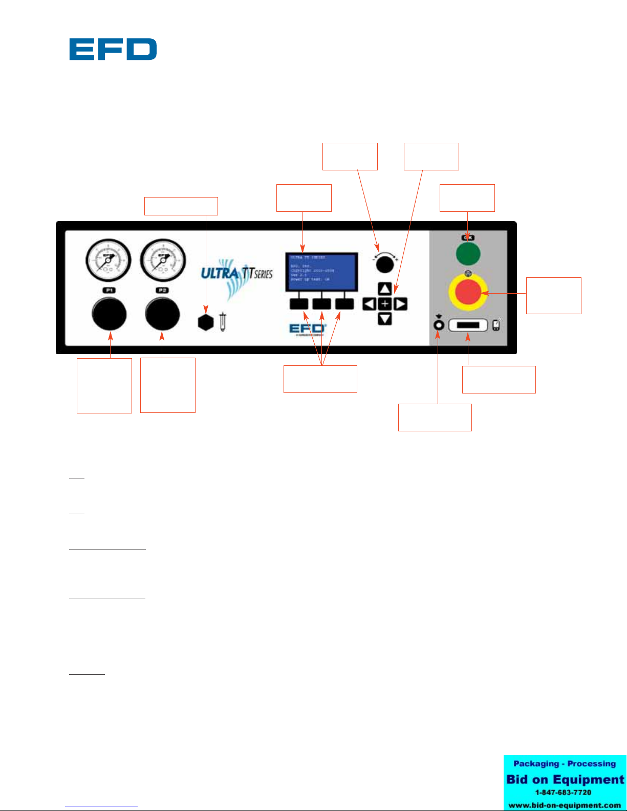
1.1.1 FRONT PANEL
14
P1 Gauge
&
Regulator
0 ~ 100PSI
LCD Menu
Scroll Knob
Emergency
Machine Off
(EMO)
Interactive
LCD
Interactive LCD
Soft Keys
Vacuum control
Ground Strap
Connector
RS232
PDA Connector
P2 Gauge
&
Regulator
0 ~ 30 psi
X/Y, Z/T
Jog Keys
Power
Button
P1: 0-100 psi pneumatic channel. To adjust the pressure, first unlock the pressure knob by pulling outward,
turn it to the right to increase pressure or left to reduce pressure. Push the knob inward to lock.
P2: 0-30 psi pneumatic channel. To adjust the pressure, first unlock the pressure knob by pulling outward,
turn it to the right to increase pressure or left to reduce pressure. Push the knob inward to lock
Vacuum control: The vacuum is connected in parallel so both P1 & P2 channels can maintain a vacuum. To
adjust the vacuum pressure, turn the control knob to the left to increase vacuum and turn it right to decrease
vacuum.
Interactive LCD: This is where you can view the current program selected, call up new programs, run tip
offsets or purge routines, pause or resume a program. The LCD also outputs user-defined messages along
with error messages. The arrow keys: X/Y, Z/T keys work in conjunction with the LCD that prompts the user
to either teach current position or teach new position for tip location at origin. The keys are selectable
between XY and ZT modes.
E-Stop: The large red button with the yellow indicator shuts off power to all actuating devices such as
servomotors and pneumatic circuits. To reset power, you must turn the red button clockwise to release then
press the green button to restore power to the actuator. This button should only be used for real emergency
stops. If you want to abort a program, press the soft key directly beneath the word “abort” on the LCD panel.

®
A NORDSON COMPANY
Ultra TT User's Guide
Version 1.2
1.1.2 BACK PANEL
15
RS232: The RS232 port can be used to connect the Ultra TT System to a Computer or PDA. The Socket
Bluetooth Adapter is connected here.
Discrete I/O: There are four digital I/Os, one analog I/O, and two 24VDC solenoid drivers. The Discrete I/Os
are used in conjunction with the control of any dispensing options or devices that require a position
reference within a program.
General Purpose Outputs: There are 16 General Purpose Outputs. They are either sinking or sourcing. The
GP I/Os are used in conjunction with the control of any dispensing options or devices that require a timing
reference within a program.
General Purpose Inputs: There are 16 General Purpose Inputs. The General Purpose Inputs are 24VDC, sink
to ground. They are used in conjunction with the control of any dispensing options or devices that require a
timing reference within a program.
Safety Interlock: If the Interlock signal is interrupted, the Interlock immediately stops all dispensing activity
to protect the operator from injury.
Main Air Entry: This connects to the facility air supply. The Ultra TT System requires 85 l/min (1SCFM)
maximum of clean, dry air (no oilers) delivered no more than 100 psi.
Main Power Input: The Main Power Input connects the dispensing system to the facility power supply. The
Ultra TT System has an automatic sensing power supply integrated into the main power supply. It uses a
main power supply between 100 Vac to 240 Vac (+/- 10%), 50-60 Hz.
Main Power Circuit Breaker: The Main Circuit Breaker is the main power switch for the System. It protects
the System from facility power surges and controls the flow of facility AC power supplied to the Power
manager.
Socket™
Adapter
attached to
RS232 Discrete I/O
Ethernet General
Purpose
Inputs
General
Purpose
Outputs
Exhaust Fan
Main Air
Entry
Main Power
Circuit
Breaker
Main Power
Input
Safety
Interlock

®
A NORDSON COMPANY
Ultra TT User's Guide
Version 1.2
1.2 MACHINE MOVEMENTS
The Ultra TT dispensing system uses an advanced microprocessor to simultaneously control three
axes of motion. An optical encoder feedback system provides closed-loop control to accurately
position the dispensing tip whether dispensing lines, dots or contoured paths.
The Ultra TT Automation system is a three-axis fluid
dispensing platform. The three degrees of freedom
provided are X/Y/Z. The motions are indicated in the figure
to the left.
The actual strokes of these axes vary depending on the
model. The X-axis movement is side to side. The Y-axis
movement is forward and backward, while the Z-axis
movement is up and down. The mechanical home is
determined by the location of each axes’ home sensor.
In the case of the Ultra TT, the home position is with the
X-axis to the left, Y-axis to the back and Z-axis is up.
1.3 A TYPICAL OPERATION
A typical operation is described below. Note that setup and programming procedures are not
included in the description.
• The part(s) is manually loaded and secured onto the tooling plate5.
• Operator activates the system by pressing the start button on the front of the machine.
• The dispensing head then moves to the programmed X/Y position and the height sensor
probe is lowered to establish the correct dispense height based upon the dot or line
parameter dispense gap. If the height sensor is disabled, then the dispensing head simply
moves to the preprogrammed dispense height.
• Fluid is dispensed onto the part, according to the pre-programmed dispensing pattern.
• Once the dispensing procedure is complete, the dispensing head will move back to its
preprogrammed park location.
• When the tooling plate returns to the park location, the completed part can now be
removed from the tooling plate.
• The process is then repeated.
16
5Purchased from EFD or User to supply their own.
X Axis
Y Axis
Z Axis

®
A NORDSON COMPANY
Ultra TT User's Guide
Version 1.2
2 Setup
2.1 Preparing the Work Area
Place the Ultra TT system on a stable table or bench. The Ultra TT needs enough space behind
the machine (at least 250mm) to allow for the tooling to move to its home position. This space
also ensures the fan duct on the back of the machine is not obstructed and thereby allows for air-
cooling of the internal electronics.
Allow enough room to place fluid reservoir pressure tank beside the machine. Fluid cartridges may
be mounted to the uprights using the M8 T-Slots on either side of the Ultra TT.
2.2 Main Air and Electrical
It is important that you have dry, clean filtered air that is aerosol free to prevent problems with the
pneumatic system of your new Ultra TT system. Input air should not be more than 100 psi. If you
have any doubts about your air supply, you should purchase one of the two filter regulator sets
listed below.
Main air input is located immediately to the left of the Fan Duct on the back panel of the machine
and accepts 6mm diameter tubing. Simply push the 6mm tubing into the push-fit connector.
Each unit is shipped with two power cords. Plug the appropriate power cord into the three-prong
power cord slot located on the back of the machine next to the main power circuit breaker. The
machine is equipped with a self-regulating power supply and will accept 100VAC ~ 240VAC +/- 10%,
50 ~ 60 Hz input voltage.
17
2000F755TT Five-micron filter regulator
Order this if you do not have dry clean
filtered factory air supply
2000F756TT Five-micron filter regulator
with coalescing filter to remove
aerosols from air supply
Plant air, 125 psi maximum to
regulator. Output from regulator
should be a minimum of 80 psi,
maximum of 100 psi.
Air input
hose

®
A NORDSON COMPANY
Ultra TT User's Guide
Version 1.2
2.3 MOUNTING WORK-HOLDING FIXTURE
Use the four tapped (4) M4 holes on the Y-Carriage to mount your work-holding fixtures.
It is important your work-holding fixture is mounted on the Y-carriage in a manner that it is parallel
to the X-beam. Flatness of your fixture is important because it makes programming much easier.
The Ultra TT system is 3D-capable and can be programmed to compensate for changes in Z-Height
over the work envelope with the use of the built-in height sensor. However, invoking the built-in
height sensor continuously through a dispensing program will significantly reduce throughput.
EFD offers two versions of fixture plates that can be used with the Ultra TT system. When
dispensing onto low profile parts, it may be necessary to raise the fixture plate up so that the
part(s) is within reach of the dispense valve. Refer to Section 9 (Accessories) for more information.
2.4 CONNECTIONS ON THE Z-HEAD
P1 quick-connect is connected to the 100 psi channel used for valve
actuation and thicker fluids when using an EFD barrel reservoir. Line
pressure is adjusted using the regulator marked P1 on the front
panel.
P1 pressure on the front panel should be set to 70 psi when using
any EFD air-actuated valve.
P2 quick-connect is connected into the 30 psi channel used for valve
nozzle air on dual input valves and lower viscosity fluids when using
an EFD barrel. Line pressure is adjusted by using the regulator
marked P2 on the front panel.
When using a single air input valve, the P2 channel can be used to
adjust the fluid pressure reservoir if 30 psi is sufficient. If you require
more than 30 psi of fluid pressure, in situations where higher
viscosity materials are used, use the Aux Air connection instead.
Aux Air quick-connect is usually used to supply fluid pressure. It is
connected to the E-stop circuit. Fluid pressure will drop to 0 psi
during emergency stop situations. Resetting the E-Stop switch and
initializing the machine will return fluid pressure to normal.
To regulate to the required pressure for a barrel-supplied valve for
pressures in excess of 30 psi, use EFD barrel pressure regulator kit
(P/N 1117HTT) that attaches to the Z head with special mounting
hardware and connects to Aux Air.
18

The terminal blocks located on top of the Z-
Head provide the connections needed to drive
Auger valves, height sensors, laser pointers and
auxiliary sensors.
Note: The height sensor has been pre-wired for
your convenience.
®
A NORDSON COMPANY
Ultra TT User's Guide
Version 1.2
19
Terminal Block Pin No Function
4 Pos 1 790 Valve (+)
4 Pos 2 790 Valve ( - )
4 Pos 3 24VDC (+)
4 Pos 4 Spare
Terminal Block Pin No Function
7 Pos 6 5VDC (+) (red)
7 Pos 7 HS Touch (green)
7 Pos 8 GND (black)
7 Pos 9 Laser Drive (blue)
7 Pos 10 24VDC (+)
7 Pos 11 Aux Sensor
7 Pos 12 Spare

®
A NORDSON COMPANY
Ultra TT User's Guide
Version 1.2
2.5 VALVE/SYRINGE BARREL CONNECTIONS
The following chart summarizes how different EFD valves/syringe barrels should be connected to
the Z-head. Note that if more than one valve/syringe barrel is required for the application, a separate
dispenser controller for each addition will be required.
The Ultra TT system is a self-contained fluid-dispensing positioning system. It features integrated
dispensing functions to operate any EFD valve or syringe barrel. The valve/syringe barrel attaches to
the Z-carriage with the appropriate mounting fixture, and all pneumatic lines plug into the EFD
quick-connect on the top of the Z-head.
Note: Your deposit size has a direct correlation to fluid pressure, time, tip size, dispense gap and
dispense speeds. To get desired results, you may need to experiment with different tip sizes,
dispense gaps, pressures and speeds.
It is important to review the material specification sheet of the fluid to be dispensed and ensure that
the proper personal protection equipment (such as footwear, gloves, etc.) is used with the type of
fluid dispensed.
The following chart summarizes how different EFD valves/syringe barrels should be connected to
the Z-head. Note that if more than one valve/syringe barrel is required for the application, a separate
dispenser controller for each addition will be required.
20
EFD Dispensing Air Connection Air Connection Fluid Pressure Connection
Valve/Syringe barrel (actuating) (atomizing)
752V-UHSS P1 N/A P2 or Auxiliary Air
725DA-SS P1 N/A P2 or Auxiliary Air
725HF-SS P1 N/A P2 or Auxiliary Air
740V-SS P1 N/A P2 or Auxiliary Air
736HPA P1 N/A P2, Auxiliary Air or customer
supplied
780S-SS P1 P2 Auxiliary Air
790 Terminal 1+ N/A P2 Selectable between pulsed
Terminal 2 - N/A or constant pressure
Syringe barrel 0~100 psi P1 N/A Same as actuating
Syringe barrel 0 ~ 30 psi P2 N/A Same as actuating
5800MP P1 N/A Same as actuating
HP4X™ P1 N/A Same as actuating
HP7X™ P1 N/A Same as actuating
2800 N/A N/A N/A
This manual suits for next models
1
Table of contents
Other EFD Dispenser manuals


