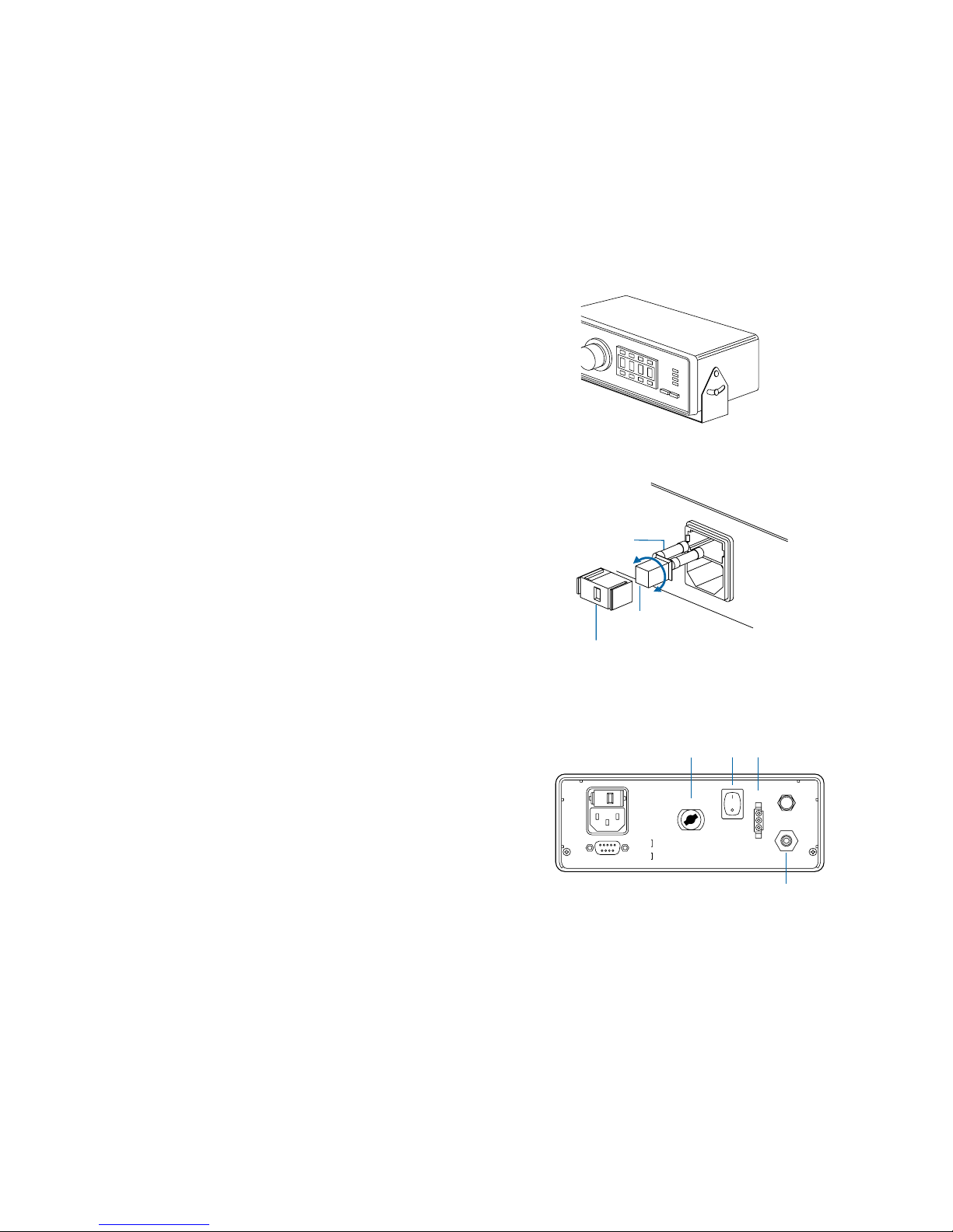
EFD 2000XL User manual

STEADY
RUN
SETUP
CYCLE
STOP
Cell Select
Run
Setup Fast Slow
Time Set
Steady
Teach Pressure
Time
Fast Slow
Time Set
Pressure
Vacuum
Vacuum
Pressure
®
A NORDSON COMPANY
Operating Guide
2000XL Series Digital Dispensers
®
A NORDSON COMPANY
In the US: 800-556-3484 In the UK: 0800 585733 In Mexico: 001-800-556-3484
2000XL 2000XL-PR5-15 2000XL-CA
••

☎
The EFD Pledge
We pledge that you will be completely satisfied with our products.
We endeavor to ensure that every EFD product is produced to our
no-compromise quality standards.
If you feel that you are not receiving all the support you require, or if
youhaveanyquestionsorcomments,Iinviteyoutowriteorcallme
personally.
Our goal is to build not only the finest equipment and components,
but also to build long-term customer relationships founded on
superb quality, service, value and trust.
Introduction
The 2000XL Series dispensers provide years of trouble-free,
productiveservice. ThisOperatingGuidewillhelpyoumaximizethe
usefulness of your new dispenser.
Pleasespendafewminutestobecomefamiliarwiththecontrolsand
features of your new dispenser. Follow our recommended testing
procedures. Reviewthehelpfulinformationwehaveincludedbased
on over 30 years of industrial dispensing experience.
Most questions you will have are answered in this guide. However,
ifyouneedassistance,pleasedonothesitatetocontactEFDoryour
authorized EFD distributor.
In the US, call 800-556-3484.
In Mexico, call 001-800-556-3484.
In the UK, ring free 0800 585733.
Randall Richardson, President

Getting Started .............................................................................4
Specifications
First Steps ....................................................................................5
Unpacking the dispenser & Activating your Ten Year No-fault Warranty
Features and Controls.............................................................. 6-7
Indicator Lamps ....................... 7
Setup..................................................................................... 8-10
Setup procedures..................8-9
Diagram .................................10
Final checklist ........................ 10
Testing the 2000XL .............................................................. 11-12
Programming deposit size ..... 12
Operational Features .................................................................13
ULTRA Dispensing System.................................................. 14-15
How to Use the Vacuum Control.......................................... 16-17
Loading the Barrel Reservoirs.............................................. 18-19
Memory Function ................................................................. 20-21
Input and Output Connection Instructions................................. 22
Schematic and Replacement Parts List .....................................23
Troubleshooting .........................................................................24
Suggestions and Reminders ......................................................25
Reordering Components ............................................................26
Ten Year No-fault Warranty .......................................................27
Meets applicable CSA and CE requirements.
This manual is for the express and sole use of EFD
dispenser purchasers and users, and no portion of
this manual may be reproduced in any form.
EFD, ULTRA System, LV Barrier and SmoothFlow
are trademarks of EFD Inc. ©2002 EFD Inc.
Contents

STOP
Steady
Run
Setup Fast Slow
Time Set Pressure
Time
Time Set
Fast Slow
STEADYSTEADY
RUN
SETUP
CYCLE
7.470"
19.0 cm
5.570"
14.1 cm
2.700"
6.9 cm
3.380"
8.6 cm
Pressure
Vacuum
Cell Select
Vacuum
Pressure
Teach
A NORDSON COMPANY 2000XL
The 2000XL Series automatic fluid dispensers are designed to
provide complete process control using advanced microprocessor
circuitry. Allmicroprocessorfunctionsareaccessedbypushbutton.
Microprocessor features include:
• Push-button time setting input or one-touch time programming.
• Floatingdecimal,providingdispensetimerangesof0.001to9.999
and 00.01 to 99.99 seconds.
• Backlit LCD displays time settings, dispensing pressure and
vacuum pressure.
• Dispensingpressure display is programmable for either psi or bar
scale.
• Memory with storage for up to eight separate time settings.
Intelligent technology makes the 2000XL Series easy to set up and
use. With one-touch setup, just press the pedal to determine the
proper amount. The microprocessor remembers the time and
repeatsthis amount with eachcycleuntil you are readytochange it.
From microdeposits to volumetric filling, the 2000XL provides the
ultimate in control and versatility for time/pressure-based fluid
dispensing.
Note: Specifications and technical
details are subject to engineering
changes without prior notification.
Specifications
Cabinet size: Weight
7.470 x 5.570 x 2.700" 3 lb 3 oz
(19.0 x 14.1 x 6.9 cm) 1.44 kg
Input voltage:
Selectable 100/120/220 VAC
50/60 Hz 10/9 VA
End-of-cycle feedback circuits:
5 to 24 VDC N.C. solid-state switch
250mA maximum (details page 23)
Initiate circuit: Foot pedal or
5 to 24 VDC signal
Air consumption: Approximately 1.5
SCFM at 400 cycles per minute
Cycle rate: Exceeds 600 per minute
Timerange: Programmable 0.001to
9.999, or 00.01 to 99.99 seconds
2000XL
air input:
80 to 100 psi (5.5 bar to 6.9 bar)
air output:
0 to 100 psi (0 to 6.9 bar)
2000XL-PR5
air input:
10 to 50 psi (0.7 bar to 3.4 bar)
air output:
0 to 5 psi (0 to .34 bar)
2000XL-CA
air input:
80 to 100 psi (5.5 bar to 6.9 bar)
air output:
0 to 15 psi (0 to 1.0 bar)
Getting Started

First: Unpackandusethechecklist enclosedwith theDispenser Kit
to identify all items. If there is any discrepancy, please call us
immediately.
Second: Powerandcompressedplantairshouldbeavailablewhere
thedispenseristobesetup. Inputairshouldbesetbetween80and
100 psi (5.5 and 6.9 bar). For model 2000XL-PR5, input air should
be set between 10 and 50 psi (0.7 and 3.4 bar). If you are not using
an EFD five-micron filter regulator #2000F755, be certain your
plant air is properly filtered and dry and a regulated, constant
air pressure is supplied to the dispenser.
Note: Model 2000XL-CA is supplied with an EFD five-micron filter
regulator with coalescing filter (#2000F756).
Bottled nitrogen can be used.
Warning: If high pressure bottled air or nitrogen is used, a high
pressure regulator must be installed on the bottle and set at 100 psi
maximum. The 2000F755 filter regulator is not required.
Check the voltage label to be certain it is set to the available power.
Third: Now is a good time to ACTIVATE your extended Ten Year
No-fault Warranty. Please fill in and return the postage paid
Warrantycard. Orifyouprefer,calltheappropriatetoll-freenumber
listed below, provide the serial number of your dispenser and
respond to a few short questions.
In the US, call 800-556-3484.
In Mexico, call 001-800-556-3484.
In the UK, ring free 0800 585733.
First Steps
☎

Digital Time, Air Pressure and
Vacuum Pressure LCD Display
•Programmablefloatingdecimalprovidestimerange
readout from 0.001 to 99.99 seconds.
•Air pressure readout can be programmed in either
psi or bar.
•Vacuum pressure readout is displayed by holding
the vacuum toggle switch in the "up" position.
Memory
Can store up to eight Time settings. (See page 20.)
Run/Setup
1. The RUN mode allows access to all eight cells. Cell
numbers are displayed as CEL1, CEL2....CEL8. Chang-
ing the cell number will change the time setting corre-
sponding to that cell.
The SETUP mode provides access to selected cell
TEACH andTIME SET functions. Only in the SETUP mode
can cell time values be viewed, cleared, or changed.
2. In the RUN mode, the functions are inoperative.
Steady/Teach
In SETUP mode, pressing STEADY/TEACH will clear
the currently displayed cell setting, reset the cell
display to blinking "0000", and place the dispenser
in a TEACH mode (refer to page 12 for TEACH
procedures).
In RUN mode, pressing STEADY/TEACH will override the
timer and dispense for as long as the foot pedal is
pressed. The dispenser display will read "----" in the
STEADY mode.
Time Set ▼ (down) ▲(up)
In SETUP mode, use the TIME SET buttons to change
time settings. Left buttons scroll digits quickly; right
buttons scroll digits slowly.
Pressure/Time
PresstochangedisplayvaluesfromTIMEtoPRESSURE
or PRESSURE back to TIME.
In SETUP mode, pressure readings may be changed
from PSI to BAR and BAR to PSI by pressing and
holding the PRESSURE/TIME button for four seconds.
STOP
This button stops the dispenser immediately.
Barrel Vacuum Control
Refer to page 16 for operation.
Air Pressure Regulator
Refer to page 11 for operating instructions.
STEADY
RUN
SETUP
CYCLE
STOP
Run
Setup Fast Slow
Time Set Pressure
Time
Fast Slow
Time Set
Pressure
Vacuum
Steady
Teach
Cell Select
EL1C
V
acuum
Pressure
®
A NORDSON COMPANY
2000XL
Function
Indicator
Lamps
Air pressure
regulator
Barrel vacuum
control
Vacuum
toggle switch
Features and Controls

STEADY
RUN
SETUP
CYCLE
STOP
Slow
tPressure
Time
Slow
t
®
A NORDSON COMPANY
2000XL
Power Input Receptacle with Voltage Selector and Fuse Cartridge
Threeinputvoltagescan be used: 100 VAC, 120 VAC and 220 VAC. To
change input voltage, remove fuse cartridge and position the selected
voltage marked on the cartridge so that it shows through the window.
(Details on page 8.)
Input/Output 9 Pin Interface Connector
Theinput/outputfeaturesareusedwhenthedispenser isinterfaced with
external control circuits.
•AnEnd-of-Cyclesignal,intheformofasolid-stateswitch,closesupon
completion of the dispense cycle. Maximum load is 250mA from 5 to
24 VDC.
•The 2000XL can be initiated using a 5 to 24 VDC signal.
•Contact Closure.
(For more details, refer to page 22.)
In the upper right corner of the
front panel are four indicator
lamps. These lamps indicate
the mode of operation.
STEADY - Indicates that the
timing feature has been
overridden and that the output
is controlled by the length of
time the foot pedal is pressed.
RUN -Indicates that the
dispenser is in the RUN mode
ready to be initiated through a
dispense cycle. In this mode,
time settings cannot be
changed.
SETUP -Indicates that the
dispenser is in the SETUP
mode. In this mode, time
settings can be changed.
CYCLE - This lamp is on during
the dispense cycle.
Indicator Lamps
Fuse T 125mA 250V
100/120/220VAC
50/60Hz 10/9VA
Air
Input
Foot
Pedal
7
.
Contact Closure
5. Contact Closure
6. Chassis Ground
8. Not Used
9. Not Used
1. Initiate
+
2. Initiate
-
3. Output
+
4. Output
-
5-24 VDC
5-24 VDC
250mA
Exhaust
Air
Output
I/O 9 pin interface
connector Air input
Voltage selector
and fuse cartridge Exhaust
Foot pedal
receptacle
Power input
receptacle
Power
switch
Air output
quick-connect

Fuse T 125mA 250V
100/120/220VAC
50/60Hz 10/9VA
Air
Input
Foot
Pedal
7
.
Contact Closure
5. Contact Closure
6. Chassis Ground
8. Not Used
9. Not Used
1. Initiate
+
2. Initiate
-
3. Output
+
4. Output
-
5-24 VDC
5-24 VDC
250mA
Exhaust
Air
Output
Power switch should be off.
❶Mounting
Included is a universal mounting bracket. Mounting
hardware is installed into the four 10-32 mounting
holesonthe sidesofthe cabinet. Thebracket canbe
mounted either over or under the cabinet and will
allow the dispenser to pivot up or down 30°from a
horizontalposition. The bracket may be permanently
mounted, or attach the rubber feet included and use
thebracketas abench-toptiltstand.Four rubberfeet
ontheconsoleareprovidedifthebracketisnotused.
❷Input power
Check the input power cord receptacle. To change
voltage, remove the voltage selector from the car-
tridge, rotate it and position the correct voltage to
show through the cartridge window. Replace the
cartridge into the power cord receptacle and insure
that both sides snap securely into position.
Install the power cord.
❸Initiate connection
The2000XLisnormallyoperatedusingthefootpedal
supplied. Plug the foot pedal into the connector
located on the rear panel. An alternate method is to
apply a 5 to 24 VDC pulse to terminals 1 and 2.
❹Air input connection
A6ft.air inputhosekitissupplied. Connecttheinput
hosetofiltered,dryplantair. Formodels2000XL and
2000XL-CA, set plant air supply within 80 to 100 psi
(5.5 to 6.9 bar). For model 2000XL-PR5, input air
should be set within 10 to 50 psi (0.7 to 3.4 bar).
Attach the air input hose coupling to the dispenser.
Pull back metal ring to attach to dispenser.
❶
Setup
❷
❸
Spare fuse
Voltage value
Cartridge window
Note: Check voltage indicated
❺
Note:If filtered, dry air is not available, order an
EFD five-micron filter regulator #2000F755.
(2000XL-CA units are supplied with a five-micron
coalescing filter regulator.)
❻
❹
220
120
100

❺Power on/off
PressthePower Switchlocatedon therearpanel
to the "ON" position. The dispenser will power up
in the RUN, STEADY, or PRESSURE mode and indi-
cate which cell was selected last. (Dispenser is
shipped with
CEL1
selected in RUN mode).
❻Air output
Pushin andtwistlock the10cc adapter assembly
(part#1000Y5150). Thenumber5150is molded
on the side of the yellow head.
❼Setting the decimal
The dispenser is shipped with the decimal set at
hundredthsofasecond(00.00). Thedecimalcan
bemovedtoshowthousandthsofasecond(0.000)
as follows:
PressRUN/SETUP toplacethe dispenserin SETUP
mode.
To move the decimal, press and hold the STOP
button. After approximately 4.0 seconds, the
decimalwillmovetothethousandthsposition. To
return to the hundredths position, press and hold
the STOP button again.
Note: Changing the decimal place changes the
currenttimesettingbyafactorof10. Forexample,
5.35 seconds becomes 53.50; 15.00 seconds
becomes 1.50.
❽Setting the pressure readout
The dispenser is shipped with pressure display
programmed in psi.
Note: On models with 5 psi and 15 psi regulators,
the pressure is adjustable in 0.1 psi increments.
If bar is desired, change as follows:
PressRUN/SETUPandplacethedispenserintothe
SETUP mode. Press and hold the PRESSURE/TIME
button for 4.0 seconds. The display will change
from psi to bar. To change back to psi, press and
hold PRESSURE/TIME for 4.0 seconds.
❾Vacuum control
Vacuum is turned off (clockwise) during testing
procedures. (Refer to page 16 for operation.)
❿Vacuum toggle switch
To read vacuum pressure, hold toggle switch in
the "up" position. Readout will appear on the
digital display pad, then return to air pressure
readout when toggle is released.
Continue to page 11 for test procedures.
STEADY
RUN
SETUP
CYCLE
STOP
Steady
Run
Setup Fast Slow
Time Set
Teach Pressure
Time
Fast Slow
Time Set
Pressure
Vacuum
Vacuum
Pressure
Cell Select
EL1
C
®
A NORDSON COMPANY
2000XL
❼
❽
❿
❾

STOP
Run
Setup Fast Slow
Time Set Pressure
Time
Time Set
Fast Slow
STEADYSTEADY
RUN
SETUP
CYCLE
Pressure
Vacuum
Steady
Teach
Cell Select
Vacuum
Pressure
®
A NORDSON COMPANY 2000XL
Note: Plantair,125psi maximumtoregulator.Outputfrom
regulatorshouldbeaminimumof80psi,maximum100psi.
For model 2000XL-PR5, output from regulator should be
set at 30 psi.
❸
Check voltage label
on dispenser.
Male
quick-connect,
insert and twist
to lock.
Barrel
adapter
assembly
Air input hose
Power cord
Foot pedal
assembly
❹
❺
Note: For hookup purposes,
the connections for the 2000XL,
2000XL-PR5 and 2000XL-CA
models are identical.
❻
❶❷

Setup for Testing
Deposit size is controlled by TIME, PRESSURE and
TIP SIZE.
Please follow these instructions in order to test
each function. Use the convenient Dot Test
sheet included in your Test Kit.
Setup for Testing
Press RUN/SETUP ❶to set the dispenser into the
RUN mode (RUN indicator light on).
Press PRESSURE/TIME ❷and set display to
pressure.
Pull out air pressure regulator knob ❸until it
"clicks" into the unlocked position. Turn clock-
wise to adjust the pressure to 20 psi (1.4 bar).
Note: Dispensers with 5 psi or 15 psi gauges
should be tested with the clear test fluid, using a
lavender30gagetipandairpressuresetat5psi.
Refer to "How to Use the Vacuum Control" on
page 16.
Alwayssetthepressuredesiredbyturningtheair
regulator knob clockwise. To reduce the pres-
sure, turn the knob counterclockwise until the air
gauge reads a lower pressure than desired.
Then increase and stop at desired pressure.
Push knob in to lock.
Dispenserswith airpressure gaugeshigherthan
15 psi are tested using the nontoxic blue fluid
suppliedintheDotTestkit. Thisfluidisrepresen-
tative of thick, non-leveling fluids such as
sealants, pastes and greases and is used to
demonstrate the different control settings.
Attachthebarrelcontainingthetestmaterialtothe
adapter assembly ❹as shown.
Remove the orange tip cap from the end of the
dispensing barrel and attach the green 18 gage
tapered tip ❺found in the Dot Test Kit. Place the
barrel in the barrel stand.
Press STEADY/ TEACH ❻to place the 2000XL into
STEADY mode. (STEADY indicator light on.)
Rest the dispensing tip on the Dot Test sheet.
Press and hold the foot pedal until the tip fills with
test material.
Go into TIME mode by pressing STEADY/ TEACH ❻
again(STEADY indicatorlight goes out) and time is
displayed.
Press RUN/SETUP ❶to place the 2000XL into the
SETUP mode (SETUP indicator light on). Press
STEADY/ TEACH ❻to zero the display.
Continue to page 12 for tests which will demon-
strate the ease at which deposit sizes can be
established using the foot pedal or TIME SET
feature.

Program (TEACH) the Deposit Time with the Foot Pedal
When a specific time value is not known, as when first
dispensinganamount,thetimemaybeprogrammedusingthe
foot pedal.
Press RUN/SETUP to set the dispenser into RUN mode (RUN
indicatorlighton).Selectthememorycellyouwishtoprogram,
e.g.
CEL1
,
CEL2
....
CEL8
.
ReturnthedispensertoSETUPmodeandclearcellmemoryby
pressing STEADY/TEACH. The dispenser displays a blinking
"0000" to indicate that it is in TEACH mode and ready for
programming.
Holdingthebarrelasshown,restthetipontheDotTestsheet.
Press the foot pedal for about one second. Notice that the
display now shows the length of time the foot pedal was
pressed.
Keeping the tip in the same place, press the pedal again for
abouttwosecondsandaddtothefirstdeposit.Nowthedisplay
shows the total time for both deposits.
Youcanbuilduptothedesiredamountbysimplypressingthe
footpedalrepetitivelyuntilthedepositisthepropersize. Ifthe
deposit becomes too large, press STEADY/TEACH and start
again. Press RUN/SETUP to save the setting and return to the
RUN mode.
ProgramtheDepositTimewithaSpecifiedTimeSetting
Set the dispense time when the desired time SET buttons
below the display to scroll up and TIME SET buttons above the
display to scroll down. The button on the right scrolls slowly
for single digit setting; the one to the left scrolls fast.
Press STEADY/TEACH, then set the time to 1.15 seconds using
the TIME SET buttons. Press RUN/SETUP to return to the RUN
mode. Press the pedal and make a 1.15 second deposit.
Testing (continued)
Correct angle for consistent deposits.
Remember-alwaysbringthetipin
contact with the work surface at
theillustratedangle. Afterthetip
isinposition,pressthefootpedal.
Releasepedalandremovetipby
lifting straight up.

If you have any questions at this point, please call us now.
In the US, call 800-556-3484
(Between 8:30 am and 6:00 pm eastern time.)
In Mexico, call 001-800-556-3484.
In the UK, ring free 0800 585733.
☎
Don’t Forget!
✓Changes to the time settings can be
made only when the mode of operation
is SETUP.
✓RUNmodelocksoutTIMESETandTEACH
control buttons. Use this to protect the
setup from inadvertent changes.
✓Pressing STEADY/TEACH in SETUP mode
will clear all time settings within cell.
✓STOP immediatelyterminates the current
dispense cycle.
✓Use only dry, clean, filtered air.
Note: The pedal needs only to be pressed mo-
mentarily. The complete time cycle will run once
the dispenser is initiated.
Press RUN/SETUP and toggle back to the SETUP
mode. Press the TIME SET buttons and change
the time to 2.30 seconds. Go back to RUN, press
the foot pedal, and the dispenser will make a
deposit approximatelytwicethesizeofthefirstone.
Pressure—changes deposit size.
The dispenser should be in the RUN mode, the
TIME setting should be 2.30 seconds and the
dispensing pressure should be 20 psi (1.4 bar).
Increasingthepressurewillresultinlargerdepos-
its, decreasing the pressure will result in smaller
deposits. Try this now and observe the results.
Tip Size—changes deposit size.
Tipsizealsoaffectsdepositsize. Withoutchang-
ingtheTIMEorPRESSURE setting,trydifferenttips
and observe the results.

Advanced Dispensing System
Ifyoudispensethickfluids,severalproblemsmay
occur. First, the repetitive air cycles can bore
tunnels through non-leveling fluids, causing
spitting and inconsistent deposits. Second, thick
fluids contain trapped air that leads to drooling
and oozing.
These problems are eliminated by using the
SmoothFlow™piston. That's because the white
pistonspreventtunnelingbyprovidingabarrierto
the pulsed-air cycles, and prevent oozing by
responding to the pressure of trapped air with a
slight suck-back movement after the dispense
cycle.
The white piston is used for most fluids.
However, if you are applying RTV silicone and
findthatthepistonbouncesandcausesstringing,
switch to the orange, flat wall piston.
The SmoothFlow™pistons make barrel filling
easier, too. As you load the fluid in, air is trapped
in the bottom and throughout the fluid. Simply
insert a SmoothFlow™piston and gently press
down on the fluid as far as possible. This action
forcesoutmostoftheairandresultsinconsistent
deposits.
For Thick Fluids
Air Pressure
OFF
Air Pressure
ON
No drip
or ooze.
TM

For Thinner Fluids
Fumes cannot escape.
SmoothFlow™piston
prevents fluid backflow.
For Cyanoacrylates
or Watery-thin Fluids
Note: If you choose not to use the piston,
please refer to page 17 for instructions.
No air gap when using the
SmoothFlow™piston.
Blue LV Barrier™for improved
control of very low viscosity fluids.
Note: The LV Barrier ™works best
with an air gap between the barrier
and fluid.
Maximum
1/2 fill
Ifyouuselowtomediumviscosityfluids,thewhite
SmoothFlow™piston has several advantages.
First, vacuum adjustment is much less sensitive.
Second, the piston prevents fumes from the fluid
beingexhaustedintotheworkenvironment. Third,
the piston prevents fluid backflow into the dis-
penser if the barrel is inadvertently turned upside
down. Fourth,using the piston makesit easy and
safe to change tips without dripping.
Note: Ifyouusewatery-thinfluidssuchassolvents,
cyanoacrylatesandanaerobics,specifytheULTRA
System™with the blue LV Barrier™
. Available in
3cc and 10cc sizes.

The vacuum control allows low viscosity fluids, even water, to be
consistentlydispensedwithoutdrippingbetweencycles. Thevacuum
exerts a negative pressure on the liquid in the barrel and prevents
dripping.
For these tests, you will use the test barrel with the clear fluid.
1. Whileholdingthebarreluprightinonehand,removetheorange
end cap and insert the blue LV Barrier™. Allow an air gap as
shown.
2. Attachthebarreltothe10ccadapter. Snapthesafetycliptightly
closedtoprevent any dripping or bubbling. Remove the tip cap
and attach the 30 gage (lavender) tip.
3. Set air pressure at 5 psi.
4. Press RUN/SETUP to go into SETUP mode and set TIME for 00.05
seconds. Press RUN/SETUP to return to RUN mode.
5. Press STEADY/TEACH (STEADY indicator light on).
6. Withthebarrelpointingdownwardoveracontainer,unsnapthe
safety clip and press the foot pedal to fill the tip.
7. If a drop begins to form at the end of the tip, slowly turn the
vacuum control knob counterclockwise to stop the drop from
growing. Wipe the tip and adjust vacuum as necessary.
8. Toreadvacuumpressure,pressPRESSURE/TIMEsothatsystem
airpressure is displayed. Holdtoggleswitch in the "up"position
to view vacuum pressure. Release toggle to return display to
system air pressure readout.
9. Press STEADY/TEACH (STEADY indicator light off).
10. Takethebarrelandplacethetiponthetestsheet. Pressthefoot
pedalandrelease. Checkthedotsize. Increaseordecreaseby
adjusting pressure or time.
Remove
orange
end cap.
Insert
blue LV
Barrier™
How to use the Vacuum Control
Remove
tip cap.

If you choose not
+to use the piston, please follow these instructions carefully:
1. While holding the barrel upright in one hand, twist on an orange
tip cap. Using the small funnel, fill about 2/3 full with your fluid.
2. Open the safety clip and attach the barrel to the 10cc adapter.
3. Close the safety clip as tight as possible.
4. Slightly increase vacuum by turning vacuum control knob
counterclockwise.
5. Then, without tipping the barrel upside down, remove the tip cap
and attach the 30 gage (lavender) tip.
6. Openthesafetyclip.Yourmaterialmaybegintobubble. Reduce
vacuum by turning vacuum control knob clockwise.
7. Ifadropbeginstoformattheendofthetip,slowlyturnthevacuum
control knob counterclockwise to stop the drop from growing.
Wipe the tip and adjust vacuum as necessary.
Now the fluid is in proper balance. It does not bubble or drip.
Repeat tests as before, keeping the air pressure low and adjusting
the time for different deposit sizes.
Do not tip the barrel upside down
or lay flat. This will cause the
liquid to run into the dispenser.
When changing tips
or attaching a tip cap,
snap the safety clip
completely closed to
prevent any dripping
or bubbling.
Three things to remember
If you do not use the piston when
dispensing thin fluids:
Use an EFD filter trap
(#1000FLT-Y). This
filter trap will impede
the flow should the
low viscosity liquid be
sucked back towards
the dispenser.
Open
Closed
☎
In the US, call 800-556-3484.
In Mexico, call 001-800-556-3484.
In the UK, ring free 0800 585733.

Loading the Barrel Reservoirs
Caution: Donotcompletelyfillbarrels.Theoptimumfillisamaximum
2/3 of the barrel capacity and 1/2 of the barrel capacity when using
the LV Barrier™
.
If the fluid you are dispensing is pourable, take the barrel, twist on a
tip cap and pour your fluid in. If appropriate, insert the SmoothFlow™
piston(seepage14). Carefullypressthepistondownuntilitcontacts
the fluid. The barrel is now ready for use.
Ifyouaredispensingwaterysolvents,cyanoacrylatesoranaerobics,
use the LV Barrier™
. Place barrier in the top of the barrel reservoir.
Allow air between barrier and fluid. Do not contact the barrier to the
fluid.
Ifyourfluidisthickornon-leveling,youcanspoonitintothebarrelwith
aspatula. Or, if thefluid comes packedina 1/10 galloncartridge, try
loadingthebarrelwithacaulkinggun.Then,pressintheSmoothFlow™
piston to move the fluid to the bottom of the barrel and to remove
trapped air.
2/3
maximum
fill
Fill procedure for
pourable fluids
White
SmoothFlow™
piston
Fill procedure for thick fluids
(shown: caulking gun)
2/3
maximum
fill Fill procedure for cyanoacrylates
or watery-thin fluids
LV Barrier™
Air gap
1/2 maximum fill

Filling the cartridge
for the barrel loader.
EFDoffersproductivealternativestotraditionalbarrelloadingmeth-
ods. Here are a few suggestions that can help keep your work area
clean,save time and reduce the chance of entrapped air in the fluid.
1. YoucouldusetheEFD#920BLbarrelloader. Packthefluidinto
the 12 ounce cartridge as shown. Then place the prefilled
cartridge into the barrel loader. Using air pressure, the barrel
loader fills the barrel (with piston) from the bottom up.
Ifthefluidcomes packedina1/10gallon(300ml.) caulkingtype
cartridge, use the EFD #940BL barrel loader.
2. If you receive frozen epoxies or other fluids in medical type
syringes with a manual plunger, request our luer-to-luer fitting
#2160 to transfer the material.
Please call an EFD Fluid Application Specialist
for additional assistance.
EFD #920BL Barrel Loader
(Specify #940BL for prefilled 1/10 gallon caulking tubes)
Barrel Rack
#905BR for 3cc and 5cc barrels
#910BR for 10cc, 30cc and 55cc barrels
2/3
Maximum
Fill
#2160 Luer-to-luer fitting

3. 2 5
EL3C
The memory feature enables storage of up to eight different time
settings that can be recalled and used at the push of a button. Time
settings are saved even with power removed and will remain in
storage unless changed or erased intentionally. Memory cells are
identified as
CEL1
through
CEL8
.
Viewing MEMORY cells
Beforesavingatimesettinginmemory,viewthememorycellstosee
which cells are empty or, if all cells are used, which time can be
replaced.
To prevent accidental data loss, review the contents of each cell
before selecting and storing a new time setting into memory.
1. Press RUN/SETUP to place the dispenser in RUN mode (RUN
indicatorlighton).Thecurrentcellnumberwillbedisplayed.e.g.,
CEL3
. (Figure 1)
2. Press CELL SELECT (up) (down) to select the cell you wish to use.
3. Press RUN/SETUP again to return the dispenser to SETUP mode
(SETUP indicator light on). The time setting stored in the selected
cell will be displayed. (Figure 2)
NOTE: To avoid unintentional loss of stored settings, do not press
STEADY/TEACH in SETUP mode (doing so will clear the previously
stored cell setting). Always return the dispenser to RUN mode after
viewing or changing contents.
Memory
Figure 1
Figure 2
This manual suits for next models
2
Table of contents
Other EFD Dispenser manuals