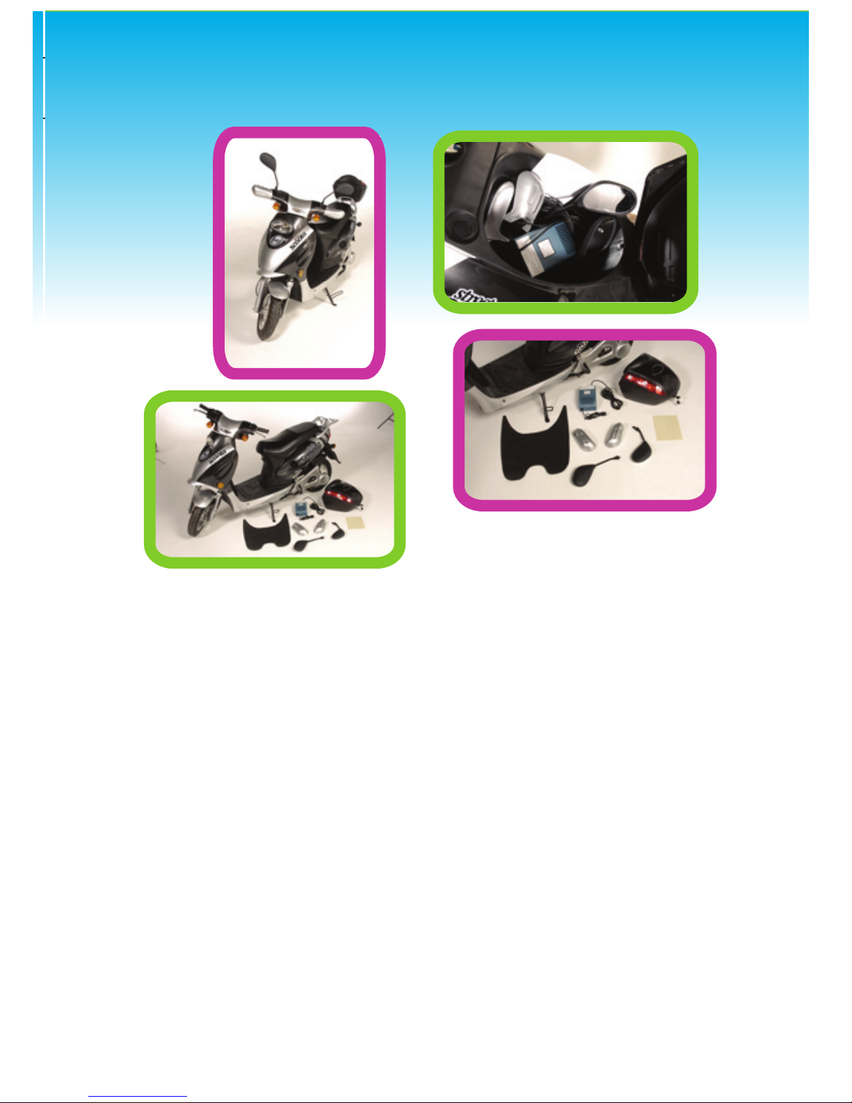
ASSEMBLY
The following information explains how to assemble the
attachment of the handle covers, mirrors and how to
charge your bike.
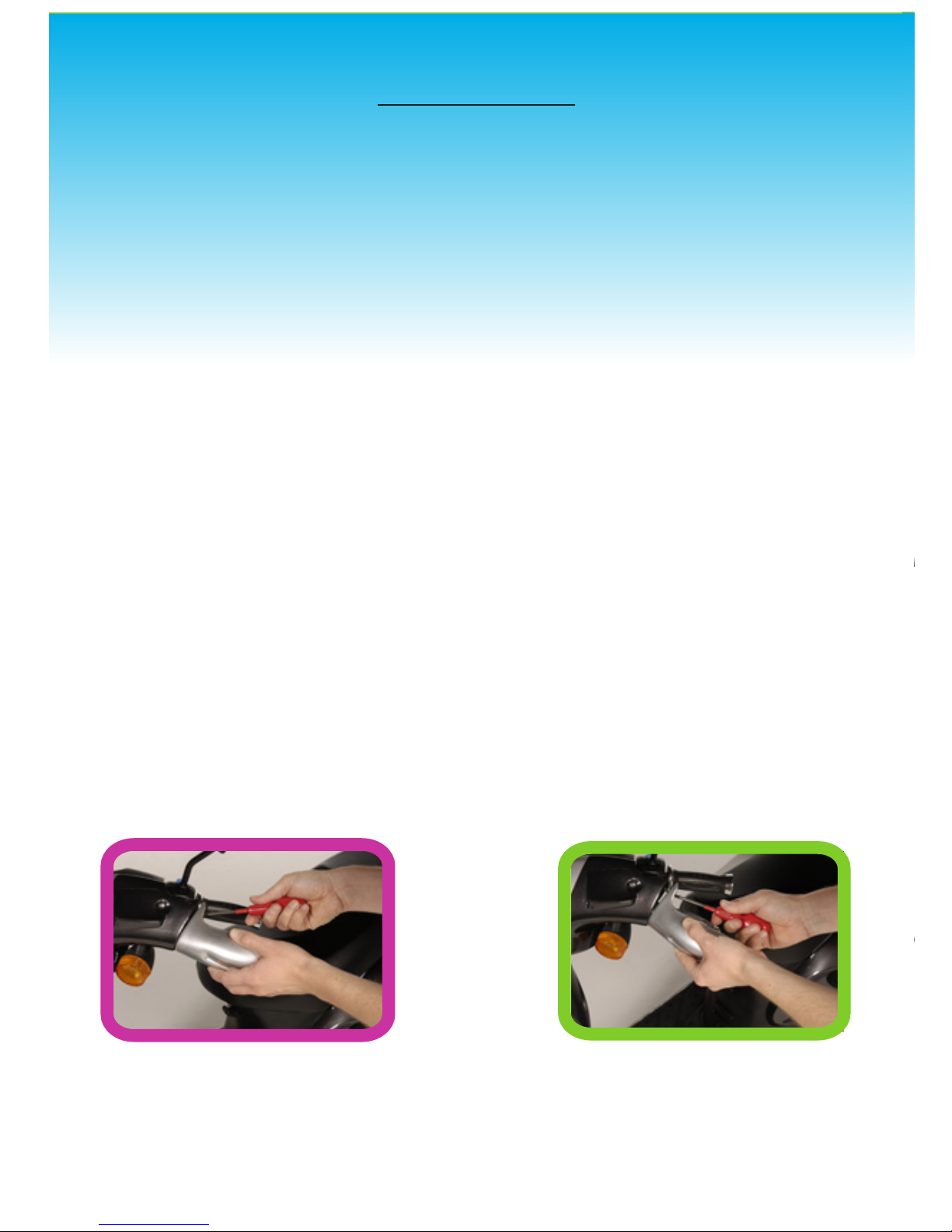
Handle Covers:
The two plastic colour coded handle covers require
attaching to the bike using a Phillips screw driver.
Taking the mirror covers and the self tapping screws
(provided) oer the mirror cover up to the handle bars
of the bike and insert using the locating tab on the cover
provided. This will ensure the cover lines up with the pre
drilled hole in the bikes handle bars. Screw the cover
onto position using the screw provided and a Phillips
screw driver.
MIRROR ASSEMBLY
Make sure you determine which is the left hand and right
hand mirror. On the top of the handle bars you will see
two pre manufactured threaded holes in the handle bars
which are for you to locate the mirrors.
Pulling back the plastic sheath on the stalk of the mirror
wind the mirror into the pre-manufactured hole until it
reaches the nut at the bottom of the thread. Then tighten
into position with the open ended 10mm spanner
ensuring that the mirrors are facing behind you when sat
on the bike. Once in position move the mirrors around to
suit your own rearward facing view requirements.